Table of Contents
Advertisement
Advertisement
Table of Contents

Related Manuals for Bender ISOMETER IRDH375


Summary of Contents for Bender ISOMETER IRDH375
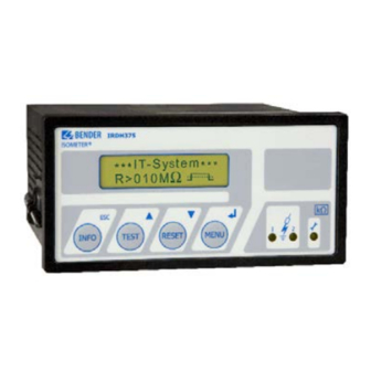
- Page 1 ISOMETER® IRDH375 IRDH375B Insulation monitoring device for IT AC systems with galvanically connected rectifiers and converters and for IT DC systems IRDH375: Software-Version D0183 V1.8 IRDH375B: Software-Version D0184 V1.8 IRDH375_D00124_05_M_XXEN/01.2020 Manual EN...
-
Page 2: Table Of Contents
Table of Contents 1. Important information ..................7 How to use this manual ................. 7 Technical support: service and support ........... 8 1.2.1 First level support ..................... 8 1.2.2 Repair service ..................... 8 1.2.3 Field service ......................9 Training courses ..................... 10 Delivery conditions .................. - Page 3 Table of Contents 4. Commissioning flow chart (threepart) ............30 5. Connection ..................... 33 Wiring ........................ 33 Wiring diagrams with coupling devices ..........37 5.2.1 Connection with AGH150W-4 ..............37 5.2.2 Connection with AGH520S ................ 39 5.2.3 Connection with AGH204S-4 ..............40 6.
- Page 4 Table of Contents 6.5.6 Setting the date (Date) (IRDH375B) ............58 6.5.7 Specifying the starting time of the automatic self test (Test) (IRDH375B) ....................... 58 6.5.8 Diagram ISO ADVANCED ................59 Menu COM SETUP: Setting the BMS interface ........60 6.6.1 Bus address „Addr:“...
- Page 5 Table of Contents 8. Factory Settings ..................... 77 9. Technical data IRDH375(B) ................79 Data in tabular form ..................79 Standards, approvals and certifications ..........83 Characteristic curves ..................84 Ordering details ..................... 91 9.4.1 ISOMETER® ....................... 91 9.4.2 Dust protection ....................92 9.4.3 Coupling devices ...................
-
Page 6: Important Information
1. Important information 1.1 How to use this manual This manual is intended for qualified personnel working in electrical engineering and electronics! Always keep this manual within easy reach for future reference. To make it easier for you to understand and revisit certain sections in this man- ual, we have used symbols to identify important instructions and information. -
Page 7: Technical Support: Service And Support
1.2 Technical support: service and support For commissioning and troubleshooting Bender offers you: 1.2.1 First level support Technical support by phone or e-mail for all Bender products • Questions concerning specific customer applications • Commissioning •... -
Page 8: Field Service
Please send the devices for repair to the following address: Bender GmbH, Repair-Service, Londorfer Str. 65, 35305 Grünberg 1.2.3 Field service On-site service for all Bender products • Commissioning, configuring, maintenance, troubleshooting of Bender products • Analysis of the electrical installation in the building (power quality test, EMC test, thermography) •... -
Page 9: Training Courses
ZVEI (Zentralverband Elektrotechnik- und Elektronikindustrie e. V.) (German Electrical and Electron- ic Manufacturer's Association) also applies. Sale and delivery conditions can be obtained from Bender in printed or elec- tronic format. 1.5 Inspection, transport and storage Inspect the dispatch and equipment packaging for damage, and compare the contents of the package with the delivery documents. -
Page 10: Warranty And Liability
Important information 1.6 Warranty and liability Warranty and liability claims in the event of injury to persons or damage to property are excluded if they can be attributed to one or more of the follow- ing causes: • Improper use of the device. •... -
Page 11: Disposal
13 August 2005 must be taken back by the manufacturer and disposed of properly. For more information on the disposal of Bender devices, refer to our homepage at www.bender-de.com -> Service & support. -
Page 12: Safety Instructions
2. Safety instructions 2.1 General safety instructions Part of the device documentation in addition to this manual is the enclosed "Safety instructions for Bender products". 2.2 Work activities on electrical installations Only qualified personnel are permitted to carry out the work necessary to install, commission and run a device or system. -
Page 13: Device-Specific Safety Information
Safety instructions 2.3 Device-specific safety information Children and unauthorised persons must not have access to or contact with the ISOMETER®. WARNING Make sure that the operating voltage is correct! Prior to insulation and voltage tests, the ISOMETER® must be disconnected from the IT system for the duration of the test. In order to check the correct connection of the device, a CAUTION functional test has to be carried out before starting the... - Page 14 Safety instructions When using ISOMETER®s in IT systems, make sure that only one active ISOMETER® is connected in each interconnected system. If IT systems are interconnected via coupling switches, make sure that ISOMETER®s not currently used are disconnected from the IT system and deactivated. IT systems coupled via diodes or capacitances may also influence the insulation monitoring process so that a central control of the different ISOMETER®s is required.
-
Page 15: Intended Use
Safety instructions 2.4 Intended use The ISOMETER® is intended for: monitoring the insulation resistance of IT systems Use for the intended purpose also includes compliance with all information in the operating instructions compliance with test intervals. ... -
Page 16: Directions For Installation
Safety instructions 2.5 Directions for installation Risk of property damage due to unprofessional installation! If more than one insulation monitoring device is connected to a conductively connected system, the system can be CAUTION damaged. If several devices are connected, the device does not function and does not signal insulation faults. - Page 17 Safety instructions Prevent measurement errors! When an AC system includes galvanically connected DC circuits, the following shall be considered: Insulation faults in DC circuits can only be monitored correctly when the rectifiers carry a continuous load of 5…10 mA. IRDH375_D00124_05_M_XXEN/01.2020...
-
Page 18: Function
3. Function 3.1 Common characteristics (IRDH375 and IRDH375B) ISOMETER® for IT AC systems with galvanically connected rectifiers and for IT DC systems (IT = unearthed systems) The operating range of the nominal voltage U can be extended via ... -
Page 19: Additional Characteristics Irdh375B
Suitable coupling devices are available to extend the nominal voltage range The IRDH375B can be used in combination with a control and indicating de- vice, e.g. PRC1470 version 2 or higher, on the BMS (BMS = Bender Measuring Device Interface) bus. -
Page 20: Function
Function 3.4 Function The ISOMETER® IRDH375 is connected between the unearthed system (IT sys- tem) and the protective conductor (PE). The response values and other function parameters are set via the function keys. The parameters are indicated on the LC display and are stored in a non- volatile memory (EEPROM) after the setting is completed. -
Page 21: Self Test
Function measuring principle "adaptive measuring pulse", a measuring principle developed by Bender (European Patent: EP 0 654 673 B1). 3.4.1 Self test A self test can be carried out manually using the TEST button or automatically. In order to guarantee high functional reliability, the ISOMETER® IRDH375 pro- vides comprehensive self test functions. -
Page 22: Relay K3: Device Fault Alarm And Eds Common Message
Function The alarm relays Alarm1/2 only switch after starting the self test function by pressing the TEST button, that means if an automatic self test has been select- ed, the alarm relays do not switch. 3.4.2 Relay K3: device fault alarm and EDS common message Relay K3 is intended to signal device and connection errors of the ISOMETER®. - Page 23 2. Switch the supply voltage off and on. 3. Contact Bender. If the on/off switching of the supply voltage is not possible for technical reasons, a RESET of the process control can be carried out by pressing the "INFO“, "RESET“ and "MENU“ key.
-
Page 24: Additional Functions Irdh375B
Function 3.5 Additional functions IRDH375B Current output for external measuring instrument The current output of IRDH375B provides 0(4)…20 mA. The current output is galvanically isolated from the device electronics and the RS-485 interface. The ISO SETUP menu, on page 43, allows to switch over between 0…20 mA and 4…20 mA. - Page 25 Function Function input F1/F2 for connection or disconnection of IT systems being monitored The ISOMETER® can be disconnected from the IT system and set to STANDBY mode with the function input F1/F2. If the input F1/F2 is bridged, the connec- tions L1/L2 are switched off via internal coupling relays, the measuring func- tion is stopped and the message "STANDBY"...
- Page 26 Function IRDH375_D00124_05_M_XXEN/01.2020...
- Page 27 Function ISOnet Function (COM SETUP) Select "ISOnet=ON" from the COM SETUP menu to activate this function. This function is a type of scanning function. The BMS Master activated via the ISOnet function controls the ISOnet Slave devices via the BMS bus. Once an ISOMETER®...
- Page 28 Function IRDH375_D00124_05_M_XXEN/01.2020...
-
Page 29: Commissioning Flow Chart (Threepart)
4. Commissioning flow chart (threepart) The encircled figures in the flow chart correspond to the figures in the legend to the wiring diagram. Commissioning of the ISOMETER® (1) IRDH375_D00124_05_M_XXEN/01.2020... - Page 30 Commissioning flow chart (threepart) Commissioning of the ISOMETER® (2) The ISOMETER® carries out a self test. The display indicates the insulation value after finishing the measurement. IRDH375_D00124_05_M_XXEN/01.2020...
- Page 31 Commissioning flow chart (threepart) Commissioning of the ISOMETER® (3) In order to check the proper connection, a functional test using a resistance that is suitable for the mains voltage is to be carried out. Size of the resistance: 50% of the present response value Alarm2.
-
Page 32: Connection
5. Connection 5.1 Wiring IRDH375(B) has plug-in terminals. Connect the terminals "A1/+" and "A2/-" to the supply voltage U in accord- ance with IEC 60364-4-43. The connections to the supply voltage shall be pro- vided with protective devices to afford protection in the event of a short circuit (a 6 A fuse is recommended). - Page 33 Connection IRDH375_D00124_05_M_XXEN/01.2020...
- Page 34 Connection Legend to wiring diagram: For external indicating instrument: IRDH375: current output, not galvanically separated: 0 … 400 µA IRDH375B: current output, galvanically separated: 0…20 mA or 4…20 mA External TEST button (NO contact) External RESET button (NC contact or wire jumper), when the terminals are open, the fault message will not be stored STANDBY by means of the function input F1, F2: When the contact is closed, insulation measurement does not take...
- Page 35 Connection Connection for external coupling devices (Extension of the nominal voltage range U Separate connection of and KE to PE The terminal pairs 2, 3 and 4 must be wired so that they are galvanically isolated and must not have a connection to PE. IRDH375_D00124_05_M_XXEN/01.2020...
-
Page 36: Wiring Diagrams With Coupling Devices
Connection 5.2 Wiring diagrams with coupling devices Please observe the settings in the "ISO ADVANCED AGH“ menu ! Adapt the settings to the coupling device to be used. 5.2.1 Connection with AGH150W-4 Connected to the ISOMETER® this coupling device extends the nominal volt- age range to DC 1,760 V in DC systems. - Page 37 Connection IRDH375_D00124_05_M_XXEN/01.2020...
-
Page 38: Connection With Agh520S
Connection 5.2.2 Connection with AGH520S Connected to the ISOMETER® this coupling device extends the nominal volt- age range to AC 7,200 V in pure AC systems. In case of 3AC systems, Pin 2 of AGH520S is to be connected to L1, in case of 3/N AC systems, Pin 2 is to be con- nected to the N conductor. -
Page 39: Connection With Agh204S-4
Connection 5.2.3 Connection with AGH204S-4 This coupling device extends the nominal voltage range of ISOMETER®s used in AC systems including rectifiers. 1 without rectifiers = 3AC 0…1,650 V (DC max. 1,000 V) = 3AC 0…1,300 V (max. AC voltage; max. DC 2 with rectifiers voltage after rectifiers in intermediate circuits of frequency converters: 1,840 V) - Page 40 Connection The maximum DC voltage is the voltage permitted to occur in the AC part of an IT system to PE when the IRDH375 is coupled with AGH204S-4 in this part of the system. This voltage is dependent on the level of the nominal voltage, the type of rectification 6 pulse, 12 pulse,…), the type of converter intermedi- ate circuit (current…...
-
Page 41: Operation And Setting
6. Operation and setting 6.1 Operating features and displays IRDH375(B) INFO key: to query standard information/ ESC key: back (menu function), confirmation parameter change TEST button: to call up the self test/ Up key: parameter change, moving up in the menu RESET button: to delete insulation fault alarms Down key: parameter change, moving down in the menu MENU key: to activate the menu system/... -
Page 42: Display In The Standard Mode
Operation and setting 6.1.1 Display in the standard mode Indication of the insulation resistance in kΩ Additional information about the insulation resistance: "s" = new measurement has started = polarity of the measuring pulse = valid bus communication signals = new entry in the memory data base = flashing, clock is to be set Messages: - Insulation fault... -
Page 43: Display In The Menu Mode
Setup status (for details refer to the table of the status numbers on page 89) COM-Setup (IRDH375 bus address) Please have the details above on hand if you have a problem and if you con- tact Bender for technical questions. IRDH375_D00124_05_M_XXEN/01.2020... - Page 44 Operation and setting Activating the TEST button starts the ISOMETER® self test. Pressing the RESET button resets insula- tion fault alarm messages stored in the ISOMETER®. The memory function is only available after activating the fault memory in the ISO SETUP menu or after bridging the terminals R1/R2. Further- more, the ISOMETER®...
- Page 45 Operation and setting ESC key: Returning from a sub menu to the previous menu. If you do not quit the menu, the device automatically returns to the standard mode again after approximately five minutes. For the sake of clarity, the following symbols are used for the functions ENTER, UP/DOWN and ESCAPE in the menu diagrams of this operating manual: IRDH375_D00124_05_M_XXEN/01.2020...
-
Page 46: Menu Structure And Menu Mode
Operation and setting 6.2 Menu structure and menu mode Switchover to the menu mode After pressing the MENU key, you can change from the standard mode to the menu mode. From the menu mode you can link to the different sub menus. Navigation within the menu Select the desired menu item using the UP/DOWN keys. - Page 47 Operation and setting Changing from the menu mode to the standard mode Pressing the ESC key allows fast changing from the menu mode to the stand- ard mode. Thus, the menu item "EXIT" need not to be activated. Automatic switchover from the menu mode to the standard mode takes place when no key is pressed for approximately 5 min in a main or sub menu.
-
Page 48: Diagram Menu Structure
Operation and setting 6.2.1 Diagram menu structure IRDH375_D00124_05_M_XXEN/01.2020... -
Page 49: Menu History Info (Irdh375B)
Operation and setting 6.3 Menu HISTORY INFO (IRDH375B) 99 events with date and time stamp can be stored in the memory database. The database is designed as a ring memory, i.e. the eldest entry is overwritten. Data is written into a non-volatile memory and therefore provides protection against voltage failure. -
Page 50: Diagram History Info (Irdh375B)
Operation and setting 6.3.1 Diagram HISTORY INFO (IRDH375B) IRDH375_D00124_05_M_XXEN/01.2020... -
Page 51: Menu Iso Setup: Setting Of The Basic Isometer® Functions
Operation and setting 6.4 Menu ISO SETUP: Setting of the basic ISOMETER® functions All alarm functions such as Alarm 1 and Alarm 2 (prewarning and main alarm), the operating principle of the alarm relays K1 and K2 (N.O = N/O operation, N.C = N/C operation) and the fault storage behaviour are set in this menu. - Page 52 Operation and setting K2: N.C Test = N/C operation contacts 21-22-24, with relay test (the alarm relay is energized during normal operation) K2: N.O Test = N/O operation contacts 21-22-24, with relay test (the alarm relay is deenergized during normal operation) K2 : N.C = N/C operation contacts 21-22-24, without relay test (the alarm relay is energized during normal operation)
- Page 53 Operation and setting Diagram ISO SETUP IRDH375_D00124_05_M_XXEN/01.2020...
-
Page 54: Memory Setting (On/Off)
Operation and setting During the automatic self test, the alarm relays are not switched over. 6.4.3 Memory setting (on/off) Memory: on = Fault memory is activated The device must be reset with the RESET button after clearing the fault. Memory: off = Fault memory deactivated (factory setting) 6.4.4 Current output for external measuring instruments... -
Page 55: Menu Iso Advanced: Setting Of The Extended Functions
Operation and setting 6.5 Menu ISO ADVANCED: Setting of the extended functions 6.5.1 External coupling devices (AGH: no) Basic setting "no", when no coupling device is used (factory setting). AGH: 204 AK80 Terminal AK of the IRDH375 is connected to terminal AK80 of the AGH204S-4. -
Page 56: Adaptation To The System Leakage Capacitance
Operation and setting AGH: 150 AK160 Terminal AK of the IRDH375 is connected to terminal AK160 of the AGH150W-4. The nominal voltage range is extended to DC 0…1,760 V. The coupling monitoring is deactivated when an external coupling device is connected. 6.5.2 Adaptation to the system leakage capacitance (Cemax : 150 µF) -
Page 57: Setting The Real-Time Clock (Clock) (Irdh375B)
Operation and setting 6.5.5 Setting the real-time clock (Clock) (IRDH375B) The setting of the real-time clock is the time base for the memory and for the automatic self test. In case of failure of the supply voltage, the real-time clock keeps running for approximately 30 days. -
Page 58: Diagram Iso Advanced
Operation and setting 6.5.8 Diagram ISO ADVANCED IRDH375_D00124_05_M_XXEN/01.2020... -
Page 59: Menu Com Setup: Setting The Bms Interface
Operation and setting 6.6 Menu COM SETUP: Setting the BMS interface 6.6.1 Bus address „Addr:“ (IRDH375B) This menu item is used to set the BMS bus address of the IRDH375B. Since there are several ISOMETER®s in one system, take care that the bus address is not assigned twice. -
Page 60: Iso Monitor (Irdh375B)
Operation and setting 6.6.3 ISO monitor (IRDH375B) This function allows to query the current measured value as well as the mes- sages of all bus-capable ISOMETER®s existing in the BMS network. After select- ing the bus address, the entire information stored by the selected device is indicated on the display. -
Page 61: Diagram Com Setup (Irdh375B)
Operation and setting 6.6.4 Diagram COM SETUP (IRDH375B) IRDH375_D00124_05_M_XXEN/01.2020... -
Page 62: Menu Password
Operation and setting 6.7 Menu PASSWORD 6.7.1 Activating and setting the password This menu can be used to activate a password query. This protects the ISOME- TER® against unauthorized settings and modifications. The desired password (menu item "2. Password: xxx") can be set with the UP/DOWN keys and con- firmed with the ENTER key. -
Page 63: Diagram Password
Operation and setting 6.7.2 Diagram PASSWORD IRDH375_D00124_05_M_XXEN/01.2020... -
Page 64: Menu Language
Operation and setting 6.8 Menu LANGUAGE 6.8.1 Setting the national language The menu item "LANGUAGE" allows fault messages of the ISOMETER® to be set to different languages. There is the choice of "German" and "English". The device menu is not influenced by the language selection. IRDH375_D00124_05_M_XXEN/01.2020... -
Page 65: Diagram Language
Diagram LANGUAGE 6.9 Menu SERVICE This menu item is provided for the Bender service personnel and is protected by a password against erroneous settings. It is intended to provide fast fault clearance by qualified experts in the event of a device error. -
Page 66: Parameterization Via Internet
Operation and setting 6.10 Parameterization via Internet The parameters of an IRDH375B indicated below can be checked and set from a remote place of use by using a personal computer. In addition, a browser (viewing program for Internet application) and the BMS Ethernet Gateway COM465 are required. -
Page 67: Serial Interfaces
For data evaluation via PC or Laptop, the terminal software "IsoData" and an interface converter of the ASCII RS-485/RS-232 type is required. To obtain the software, please contact Bender Service. Contact details are found on page 8. Interface data: RS-485 interface galvanically isolated from the device electronics ... - Page 68 Serial interfaces IRDH375_D00124_05_M_XXEN/01.2020...
-
Page 69: Interface With Bms Protocol (Irdh375B)
Serial interfaces 7.2 RS-485 interface with BMS protocol (IRDH375B) The RS-485 interface galvanically isolated from the device electronics and cur- rent output serves as a physical transmission medium for the BMS protocol. If several IRDH375B or other bus-capable devices are interconnected in a net- work via the BMS bus, the BMS bus must be terminated at both ends with a 120 Ω... -
Page 70: Topology Rs-485 Network (Irdh375B)
Serial interfaces 7.3 Topology RS-485 network (IRDH375B) The optimum topology for the RS-485 network is a daisy-chain connection. In this connection, device 1 is connected to device 2, device 2 to device 3, device 3 to device n etc. The RS-485 network represents a continuous path without branches. -
Page 71: Bms Protocol (Irdh375B)
The number of bus nodes is restricted to 32 devices. When more devices are to be connected, Bender recommends to use an RS-485 repeater DI1. 7.4 BMS protocol (IRDH375B) This protocol is an essential part of the Bender Measuring Device Interface. Data transmission generally makes use of ASCII characters. Interface data are:... -
Page 72: Bms Master
Serial interfaces 7.4.1 BMS Master A Master can query all warning and operating messages from a Slave. If the bus address 1 has been selected for one IRDH375B, this device automat- ically represents the Master, that means that all addresses between 1 and 150 are cyclically scanned via the BMS bus for alarm and operating messages. -
Page 73: Bms Slave
Serial interfaces Faults may be caused when: Addresses are assigned twice A second Master exists on the BMS bus Interference signals occur on the bus lines A defective device is connected to the bus ... -
Page 74: Commissioning Of An Rs-485 Network With Bms Protocol
Serial interfaces The following table gives an overview about essential alarm messages and the assignment of the messages indicated on the display or operator panels, e.g. PRC1470. Message Channel Meaning Insulation Fault Insulation resistance < setting Alarm 1 Insulation Fault Insulation resistance <... - Page 75 Serial interfaces BMS bus address ranges Addresses* Device Meaning There is no device with address 0 ! Information sent to address 0 applies to all devices connected to the interface (broad- cast) PRC1470 Control and indicating device 1…30 IRDH275B/ Insulation monitoring device 375B/575 1…30 COM465...
-
Page 76: Factory Settings
8. Factory Settings Menu Submenu Factory setting 1. EXIT 2. HISTORY INFO 3. ISO SETUP 1. Exit 2. Alarm1: 40 kΩ 3. Alarm2: 10 kΩ 4. K1: 5. K2: --------- N.C fixed setting 6. Memory: 7. M+/M-:* 0-20 mA* 4. ISO ADVANCED 1. - Page 77 7. LANGUAGE 1. Exit 2. Text: German 8. SERVICE (Access only for Bender service personnel) * Settings apply only to IRDH375B. Please check if the basic setting of the ISOMETER® complies with the require- ments of the system to be monitored.
-
Page 78: Technical Data Irdh375(B)
9. Technical data IRDH375(B) 9.1 Data in tabular form The values marked with * are absolute values Insulation coordination acc. to IEC 60664-1 Rated voltage..............................AC 800 V Rated impulse voltage/pollution degree......................8 kV/3 Voltage ranges IRDH375….: Nominal voltage range U ......................AC/3NAC 0…793 V* Nominal frequency f (for f <... - Page 79 Technical data IRDH375(B) Measuring circuit Measuring voltage U ............................≤ 40 V Measuring current I max. (at R = 0 Ω)...................... ≤ 220 μA Internal DC resistance R ..........................≥ 180 kΩ Internal impedance Z , at 50 Hz........................≥ 180 kΩ Permissible extraneous DC voltage U .....................
- Page 80 Technical data IRDH375(B) Switching components Switching components.......................3 changeover contacts: ........................ K1 (Alarm 1), K2 (Alarm 2), K3 (device fault) Operating principle K1, K2 (Alarm 1/Alarm 2)................N/O or N/C operation Factory setting (Alarm 1/Alarm 2)......................N/O operation Operating principle K3 ..........................N/C operation Electrical endurance......................12,000 switching operations Contact class ............................
- Page 81 Technical data IRDH375(B) Type of enclosure ........................X300, free from halogen DIN rail mounting ............................IEC 60715 Flammability class ............................UL94 V-0 Software version IRDH375 ..........................D183 V1.8 Software version IRDH375B .......................... D184 V1.8 Weight approx............................... 510 g Option "W" Shock resistance IEC 60068-2-27 (Device in operation) ................
-
Page 82: Standards, Approvals And Certifications
Technical data IRDH375(B) 9.2 Standards, approvals and certifications The ISOMETER® was designed under consideration of the following standards: - DIN EN 61557-8 (VDE 0413-8): 2015-12 - DIN EN 61557-8 Ber 1 (VDE 0413-8 Ber 1): 2016-12 - IEC 61557-8: 2014 - IEC 61557-8:2014/COR1: 2016 Subject to change! The specified standards take into account the edition valid until 01.2020 unless otherwise indicated. -
Page 83: Characteristic Curves
Technical data IRDH375(B) 9.3 Characteristic curves ISOMETER® response times in relation to system leakage capaci- tances of: = 1…500 μF, U = 0…793 V/50 Hz 1000 ≤ Ω 10 M ≥ Ω 1000 [µF] IRDH375_D00124_05_M_XXEN/01.2020... - Page 84 Technical data IRDH375(B) Max. AC voltage between the IT system and earth in the frequency range < 50 Hz IRDH375_D00124_05_M_XXEN/01.2020...
- Page 85 Technical data IRDH375(B) Current output 0…400 µA (only IRDH375) = Insulation fault in kΩ = Current output in μA IRDH375_D00124_05_M_XXEN/01.2020...
- Page 86 Technical data IRDH375(B) Current output 0…20 mA (IRDH375B) Ω Ω = Insulation fault in kΩ = Current output in mA IRDH375_D00124_05_M_XXEN/01.2020...
- Page 87 Technical data IRDH375(B) Current output 4…20 mA (IRDH375B) Ω Ω = Insulation fault in kΩ = Current output in mA IRDH375_D00124_05_M_XXEN/01.2020...
- Page 88 Technical data IRDH375(B) Status number IRDH375_D00124_05_M_XXEN/01.2020...
- Page 89 Technical data IRDH375(B) Dimension diagram enclosure IRDH375(B) All dimensions in mm panel cut-out 138 x 68 mm IRDH375_D00124_05_M_XXEN/01.2020...
-
Page 90: Ordering Details
Technical data IRDH375(B) 9.4 Ordering details 9.4.1 ISOMETER® Nominal voltage Supply voltage Type Art. No. IRDH375-435 3NAC 0…793 V AC 88…264 V B91065000 DC 0…650 V DC 77…286 V IRDH375W-435 „ „ B91065000W IRDH375B-435 „ „ B91065004 IRDH375BW-435 „ „ B91065004W IRDH375-427 3NAC 0…793 V... -
Page 91: Dust Protection
Technical data IRDH375(B) Option "W" Devices with ending "W" provide improved shock and vibration resistance. A special varnish of the electronics provides higher resistance against mechan- ical stress and moisture. This makes the devices suitable for use in ships, on rolling stock and in seismic environment. -
Page 92: Coupling Devices
Technical data IRDH375(B) 9.4.3 Coupling devices Nominal voltage range Type Art. No. AGH204S-4 AC 0…1,650 V B914013 AGH520S AC 0…7,200 V B913033 AGH150W-4 DC 0…1,760 V B98018006 9.4.4 Measuring instruments Type Measuring range Dimensions Art. No. 7204-1421 0…400 μA 72 x 72 mm B986763 9604-1421 0…400 μA... - Page 93 Technical data IRDH375(B) IRDH375_D00124_05_M_XXEN/01.2020...
-
Page 94: Index
Approvals 83 EDS4... Automatic self test 57 - Common message 23 Explanations of symbols and warnings 17 Bender Measuring Device Interface 72 External coupling devices 56 BMS bus, address ranges 76 External RESET button 35 BMS Master 73 External TEST button 35... - Page 95 INFO key 42 Real-time clock 25 Interconnected systems 25 RESET button 21 ISO monitor (IRDH375B) 61 Response values Alarm 1 and Alarm 2 set- IsoData protocol 68 ting 52 RS-485 interface 70 RS-485 network K3, system fault relay 22 - correct arrangement 71 - wrong arrangement 71 Measuring instruments 93 Memory database 50...
Need help?
Do you have a question about the ISOMETER IRDH375 and is the answer not in the manual?
Questions and answers