Table of Contents
Advertisement
Quick Links
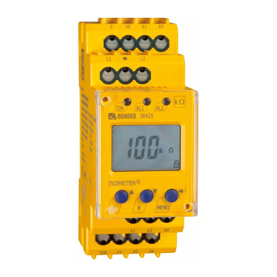
A-ISOMETER® IR425
Isolationsüberwachungsgerät
Bestimmungsgemäße Verwendung
®
Das A-ISOMETER
IR425 überwacht den Isolationswiderstand R
eines ungeerdeten AC/DC-Steuerstromkreises (IT-System) von
AC 0...300 V bzw. DC 0...300 V. Die zulässige Netzableitkapazität
C
max beträgt 20 µF.
e
Sicherheitshinweise allgemein
Bestandteil der Gerätedokumentation sind neben diesem Daten-
blatt die beiliegenden „Wichtigen sicherheitstechnischen Hin-
weise für Bender-Produkte".
Sicherheitshinweise gerätespezifisch
In jedem leitend verbundenen System darf nur ein
Isolationsüberwachungsgerät angeschlossen sein.
Vor Isolations- und Spannungsprüfungen an der An-
lage muss das Isolationsüberwachungsgerät für die
Dauer der Prüfung vom IT-System getrennt sein.
Funktionsbeschreibung
®
Das A-ISOMETER
IR425 erzeugt eine pulsierende Messspan-
nung. Diese wird über die Klemmen L1/L2 und KE/E dem zu über-
wachenden IT-System überlagert. Ohmsche Isolationsfehler
zwischen IT-System und Erde schließen den Messkreis. Der aktu-
elle gemessene Isolationswiderstand wird auf dem Display des
Geräts angezeigt.
Preset-Funktion
Nach erstem Anlegen der Versorgungsspannung U
koppeltem IT-System werden die Ansprechwerte R
(Alarm 1/2) einmalig automatisch auf folgende Werte gesetzt:
U
> 72 V: Ansprechwert 1 = 46 kΩ, Ansprechwert 2 = 23 kΩ
n
≤
U
72 V: Ansprechwert 1 = 20 kΩ, Ansprechwert 2 = 10 kΩ
n
Die Preset-Funktion wird nach Rücksetzen auf die Werkseinstel-
lungen erneut ausgeführt.
Selbsttest, automatisch
Das Gerät führt nach dem Zuschalten der Versorgungsspannung
U
und danach alle 24 h einen Selbsttest durch, bei dem interne
S
Funktionsstörungen oder Anschlussfehler ermittelt und als Feh-
lercode auf dem Display angezeigt werden. Die Alarm-Relais wer-
den dabei nicht geprüft.
Selbsttest, manuell
Durch Betätigen der internen/externen Testtaste > 1,5 s führt das
Gerät einen Selbsttest durch, bei dem interne Funktionsstörun-
gen oder Anschlussfehler ermittelt und als Fehlercode auf dem
Display angezeigt werden. Die Alarm-Relais werden dabei ge-
prüft.
Während des Drückens der Test-Taste werden alle für dieses Ge-
rät verfügbaren Display-Elemente angezeigt.
Funktionsstörung
Liegt eine Funktionsstörung vor, schaltet Relais K2 (21, 22, 24)
und alle 3 LEDs blinken. Das Display zeigt einen Fehlercode.
E01 = Schutzleiter-Anschluss fehlerhaft, keine niederohmige
Verbindung zwischen E und KE.
E02 = Netz-Anschlussfehler, keine niederohmige Verbindung
zwischen L1 und L2.
E03...Exx = Interner Gerätefehler
TBP103005 / 09.2010
Insulation monitoring device
Deutsch
Intended use
The IR425 A-ISOMETER
F
unearthed AC or DC control circuit (IT system) of AC 0...300 V re-
spectively DC 0...300 V. The maximum permissible system leak-
age capacitance C
Safety instructions
In addition to this data sheet, the documentation of the device in-
cludes a sheet entitled "Important safety instructions for BENDER
products".
Device-specific safety information
Function
The IR425 A-ISOMETER
age which is superimposed on the IT system being monitored via
the terminals L1/L2 and KE/earth. Ohmic insulation faults close
the measuring circuit between the IT system and earth. The cur-
rently measured insulation resistance is shown on the display of
the device.
Preset function
und ange-
After connecting the supply voltage U
S
/R
tem for the first time, the response values R
an1
an2
are automatically set once to:
U
> 72 V: response value 1 = 46 kΩ, response value 2 = 23 kΩ
n
≤
U
72 V: response value 1 = 20 kΩ, response value 2 = 10 kΩ
n
After resetting the device values to its factory settings, the Preset
function is automatically active again.
Automatic self test
The device automatically carries out a self test after connecting to
the supply voltage U
test, internal functional faults or connection faults will be deter-
mined and will appear in form of an error code on the display. The
alarm relays are not checked during this test.
Manual self test
After pressing the internal/external test button for > 1.5 s, the de-
vice carries out a self test. During this test, internal functional
faults, or connection faults will be determined and will appear in
form of an error code on the display. The alarm relays are checked
during this test.
With the test button pressed and held down, all device-related
display elements appear on the display.
Malfunction
In case of a malfunction, the relay K2 (21, 22, 24) switches and all
of the three LEDs flash. An error code appears on the display.
E01 = PE connection fault, no low-resistance
E02 = system connection fault, no low-resistance connection
E03...Exx = internal device error
®
monitors the insulation resistance of an
is 20 µF.
e
Only one insulation monitoring device may be used
in each interconnected system.
When insulation and voltage tests are to be carried
out, the device shall be isolated from the system for
the test period.
®
generates a pulsating measuring volt-
and later every 24 hours. During the self
S
connection between E and KE.
between L1 and L2.
English
and connecting the IT sys-
S
/R
(Alarm 1/2)
an1
an2
1
Advertisement
Table of Contents

Related Manuals for Bender A-ISOMETER IR425


Summary of Contents for Bender A-ISOMETER IR425
- Page 1 Bestandteil der Gerätedokumentation sind neben diesem Daten- In addition to this data sheet, the documentation of the device in- blatt die beiliegenden „Wichtigen sicherheitstechnischen Hin- cludes a sheet entitled "Important safety instructions for BENDER weise für Bender-Produkte“. products". Sicherheitshinweise gerätespezifisch...
- Page 2 A-ISOMETER® IR425 Verzögerungszeiten t und t Time delays t and t Die nachfolgend beschriebenen Zeiten t und t verzögern die The times t and t described below delay the indication of Ausgabe von Alarmen über LEDs und Relais. alarms via LEDs and relays. Anlaufverzögerung t Starting delay t Nach Zuschalten der Versorgungsspannung U...
- Page 3 A-ISOMETER® IR425 Anschlussplan Wiring diagram MENU ~/– TEST RESET IT-System Klemme Anschlüsse Terminal Connection E, KE Separater Anschluss von E und KE an PE E, KE Connect the leads E and KE separately to PE. A1, A2 Versorgungsspannung U (siehe Typenschild) über A1, A2 Supply voltage U (see nameplate) via 6 A fuse...
- Page 4 A-ISOMETER® IR425 Gerätefront/ Ele- Ele- Funktion Function ment Front of the device ment Betriebs-LED, grün Power ON LED, green LED Alarm 1 leuchtet( gelb): LED Alarm 1 lights ( yellow): AL1, Ansprechwert 1 unterschritten AL1, value below response value 1 AL1 AL2 LED Alarm 2 leuchtet (gelb): LED Alarm 2 lights (yellow):...
- Page 5 A-ISOMETER® IR425 Einstellen der Parameter Parameter settings Beispielhaft wird die Änderung des Alarm-Ansprechwerts R An example is given below on how to change the alarm response (R 2) beschrieben. So gehen Sie vor: value R (R 2). Proceed as follows: Drücken Sie die Taste MENU/Enter länger als 1,5 s.
- Page 6 A-ISOMETER® IR425 Verzögerungszeiten einstellen Setting the time delay Hiermit können Sie eine Ansprechverzögerung t (0...99 s) sowie Use this segment to enter the response delay t (0...99 s) and the eine Anlaufverzögerung t (0...10 s) vorgeben starting delay t (0...10 s). Reset to factory setting and password protection Werkseinstellung herstellen und Passwort-Schutz Use this menu to activate the password protection, to change the...
-
Page 7: Supply Voltage
A-ISOMETER® IR425 Technische Daten IR425-D4.. Technical data IR425-D4.. Isolationskoordination nach IEC 60664-1/IEC 60664-3 Insulation coordination acc. to IEC 60664-1/IEC 60664-3 Bemessungsspannung ......................250 V Rated insulation voltage......................250 V Bemessungs-Stoßspannung / Verschmutzungsgrad ............ 2,5 kV / III Rated impulse voltage / Pollution degree ................ 2.5 kV / III Sichere Trennung (verstärkte Isolierung) zwischen: Protective separation (reinforced insulation) between: ............... - Page 8 Änderungen vorbehalten! Subject to change! © © Dipl.-Ing. W. Bender GmbH & Co. KG Dipl.-Ing. W. Bender GmbH & Co. KG Dipl.-Ing. W. Bender GmbH & Co. KG Tel.: +49 6401 807-0 E-Mail: info@bender-de.com •...
Need help?
Do you have a question about the A-ISOMETER IR425 and is the answer not in the manual?
Questions and answers