
Related Manuals for Bender ISOMETER IRDH275


Summary of Contents for Bender ISOMETER IRDH275
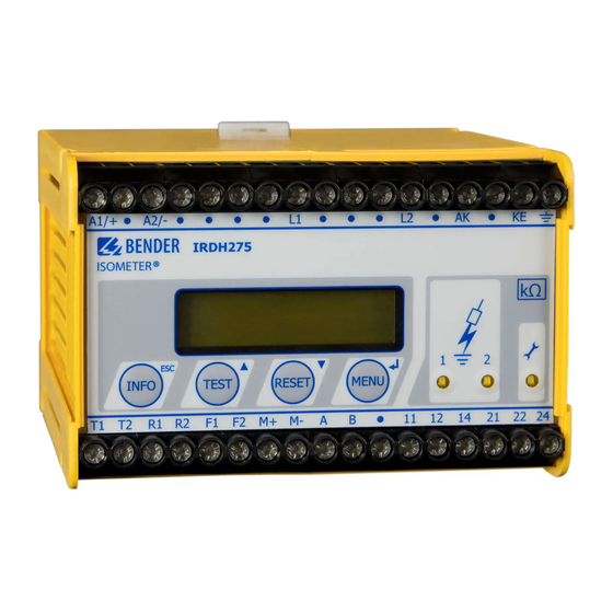
- Page 1 Manual ISOMETER®IRDH275 IRDH275B Insulation monitoring device for IT AC systems with galvanically connected rectifiers and converters and for IT DC systems Software version IRDH275: D160 V1.8 IRDH275_D00122_02_M_XXEN/10.2016...
- Page 2 Postfach 1161 • 35301 Gruenberg • Germany Tel.: +49 6401 807-0 Fax: +49 6401 807-259 Email: info@bender.de Web: http://www.bender.de © Bender GmbH & Co. KG All rights reserved. Reprinting only with permission of the publisher. Subject to change! Photos: Bender archives and bendersystembau archives.
-
Page 3: Table Of Contents
Table of Contents 1. Important information ..................7 How to use this manual ................. 7 Technical support: service and support ........... 8 1.2.1 First level support ..................... 8 1.2.2 Repair service ..................... 8 1.2.3 Field service ......................9 Training courses ..................... 10 Delivery conditions .................. - Page 4 Table of Contents 4. Connection ..................... 29 Wiring ........................ 29 Wiring diagrams with coupling devices ..........32 4.2.1 Connection with AGH150W-4 ..............32 4.2.2 Connection with AGH520S ................ 33 4.2.3 Connection with AGH204S-4 ..............34 5. Commissioning flow chart (threepart) ............37 6.
- Page 5 Table of Contents 6.5.7 Specifying the starting time of the automatic self test (Test) (IRDH275B) ....................... 56 6.5.8 Diagram ISO ADVANCED ................57 Menu COM SETUP: Setting the BMS interface ........58 6.6.1 Bus address „Addr:“ (IRDH275B) ............. 58 6.6.2 ISOnet function (IRDH275B) ..............58 6.6.3 ISO monitor (IRDH275B) ................
- Page 6 Table of Contents 8. Technical data IRDH275(B) ................73 Data in tabular form ..................73 Standards, approvals and certifications ..........77 Characteristic curves ..................78 Ordering details ..................... 85 8.4.1 ISOMETER® ....................... 85 8.4.2 Coupling devices ................... 86 8.4.3 Measuring instruments ................86 INDEX ........................
-
Page 7: Important Information
1. Important information 1.1 How to use this manual This manual is intended for qualified personnel working in electrical engineering and electronics! Always keep this manual within easy reach for future reference. To make it easier for you to understand and revisit certain sections in this man- ual, we have used symbols to identify important instructions and information. -
Page 8: Technical Support: Service And Support
Important information This manual has been compiled with great care. It might nevertheless contain errors and mistakes. Bender cannot accept any liability for injury to persons or damage to property resulting from errors or mistakes in this manual. 1.2 Technical support: service and support For commissioning and troubleshooting Bender offers you: 1.2.1... -
Page 9: Field Service
Please send the devices for repair to the following address: Bender GmbH, Repair-Service, Londorfer Str. 65, 35305 Grünberg 1.2.3 Field service On-site service for all Bender products • Commissioning, configuring, maintenance, troubleshooting of Bender products • Analysis of the electrical installation in the building (power quality test, EMC test, thermography) •... -
Page 10: Training Courses
ZVEI (Zentralverband Elektrotechnik- und Elektronikindustrie e. V.) (German Electrical and Electron- ic Manufacturer's Association) also applies. Sale and delivery conditions can be obtained from Bender in printed or elec- tronic format. 1.5 Inspection, transport and storage Inspect the dispatch and equipment packaging for damage, and compare the contents of the package with the delivery documents. -
Page 11: Warranty And Liability
Important information 1.6 Warranty and liability Warranty and liability claims in the event of injury to persons or damage to property are excluded if they can be attributed to one or more of the follow- ing causes: • Improper use of the device. •... -
Page 12: Disposal
13 August 2005 must be taken back by the manufacturer and disposed of properly. For more information on the disposal of Bender devices, refer to our homepage at www.bender-de.com -> Service & support. -
Page 13: Safety Instructions
2. Safety instructions 2.1 General safety instructions Part of the device documentation in addition to this manual is the enclosed "Safety instructions for Bender products". 2.2 Work activities on electrical installations Only qualified personnel are permitted to carry out the work necessary to install, commission and run a device or system. -
Page 14: Device-Specific Safety Information
Safety instructions 2.3 Device-specific safety information Children and unauthorised persons must not have access to or contact with the ISOMETER®. WARNING Make sure that the operating voltage is correct! Prior to insulation and voltage tests, the ISOMETER® must be disconnected from the IT system for the duration of the test. In order to check the correct connection of the device, a CAUTION functional test has to be carried out before starting the... - Page 15 Safety instructions When using ISOMETER®s in IT systems, make sure that only one active ISOMETER® is connected in each interconnected system. If IT systems are interconnected via coupling switches, make sure that ISOMETER®s not currently used are disconnected from the IT system and deactivated. IT systems coupled via diodes or capacitances may also influence the insulation monitoring process so that a central control of the different ISOMETER®s is required.
-
Page 16: Intended Use
IT systems Any other use, or any use which goes beyond the foregoing, is deemed to be use other than for the intended purpose. The Bender companies shall not be liable for any losses or damage arising therefrom. -
Page 17: Directions For Installation
Safety instructions 2.5 Directions for installation Risk of property damage due to unprofessional installation! If more than one insulation monitoring device is connected to a conductively connected system, the system can be damaged. If several devices are connected, the device does CAUTION not function and does not signal insulation faults. - Page 18 Safety instructions The devices, variant -4.. are delivered with the following factory setting: Alarm 1 / Alarm 2 = 40 kΩ / 10 kΩ ISO SETUP: (response values) Operating principle K1/K2 = N/O operation ISO SETUP: Memory = off ISO SETUP: System leakage capacitance = 150 μF ISO ADVANCED:...
-
Page 19: Function
Memory with real-time clock to store all alarm messages with date and time stamp. • BMS interface (BMS protocol) for data exchange with other Bender devices (RS485 electrically isolated). • Internal disconnection of the ISOMETER from the IT system to be moni- tored (using a control signal;... -
Page 20: Product Description
Suitable coupling devices are available to extend the nominal voltage range U The IRDH275B can be used in combination with a control and indicating de- vice, e.g. PRC1470 version 2 or higher, on the BMS (BMS = Bender Measuring Device Interface) bus. - Page 21 0…400 μA or 0/4…20 mA (IRDH275B) at M+/M- are galvanically isolated. measuring principle "adaptive measuring pulse", a measuring principle developed by Bender (European Patent: EP 0 654 673 B1). Self test A self test can be carried out manually using the TEST button or automatically.
- Page 22 Function When a device error or connection fault is found, the message "!Error!" ap- pears on the display, the device fault LED lights up, the relay K2 (21-22-24) switches and the respective fault message (see table) is indicated. If such a de- vice fault occurs, a self test is started again every minute.
- Page 23 Press TEST button 2. Switch the supply voltage off and on 3. Contact Bender If the on/off switching of the supply voltage is not possible for technical reasons, a RESET of the process control can be carried out by pressing the "ESC“, "RESET“ and "MENU“ key.
-
Page 24: Additional Functions Irdh275B
Function 3.5 Additional functions IRDH275B Current output for external measuring instrument The current output of IRDH275B provides 0(4)…20 mA. The current output is galvanically isolated from the device electronics and the RS485 interface. The ISO SETUP menu, on page 50, allows to switch over between 0…20 mA and 4…20 mA. - Page 25 Function Function input F1/F2 for connection or disconnection of IT systems being monitored ® The ISOMETER can be disconnected from the IT system and set to STANDBY mode with the function input F1/F2. If the input F1/F2 is bridged, the connec- tions L1/L2 are switched off via internal coupling relays, the measuring func- tion is stopped and the message "STANDBY"...
- Page 26 Function IRDH275_D00122_02_M_XXEN/10.2016...
- Page 27 Function ISOnet Function (COM SETUP) Select "ISOnet=ON" from the COM SETUP menu to activate this function. This function is a type of scanning function. The BMS Master activated via the ISOnet function controls the ISOnet slave devices via the BMS bus. Once an ®...
- Page 28 Function IRDH275_D00122_02_M_XXEN/10.2016...
-
Page 29: Connection
4. Connection Only qualified personnel are permitted to carry out the work necessary to install, commission and run a device or system. Risk of electrocution due to electric shock! Touching live parts of the system carries the risk of: • An electric shock •... - Page 30 Connection ® Only one ISOMETER may be connected to an external TEST or RESET button. A galvanic parallel connection of several TEST and RESET inputs for collective ® testing of ISOMETER s is not permitted. External coupling devices connected via the terminal AK cannot be switched off via the internal coupling relays.
- Page 31 Connection Legend to wiring diagram: Supply voltage U (see nameplate) via 6 A fuse For UL and CSA applications, the use of 5 A fuses is mandatory 2, 3 Connection to the 3AC system to be monitored: connect terminals L1, L2 to neutral conductor N or terminals L1, L2 to conductor L1, L2 Connection to the AC system to be monitored: connect terminals L1, L2 to conductor L1, L2...
-
Page 32: Wiring Diagrams With Coupling Devices
Connection 4.2 Wiring diagrams with coupling devices Please observe the settings in the "ISO ADVANCED AGH“ menu ! Adapt the settings to the coupling device to be used. 4.2.1 Connection with AGH150W-4 ® Connected to the ISOMETER this coupling device extends the nominal volt- age range to DC 1760 V in DC systems. -
Page 33: Connection With Agh520S
4.2.2 Connection with AGH520S ® Connected to the ISOMETER this coupling device extends the nominal volt- age range to AC 7200 V in pure AC systems. In case of 3 AC systems, Pin 2 of AGH520S is to be connected to L1, in case of 3/N/AC systems, Pin 2 is to be connected to the N-conductor. -
Page 34: Connection With Agh204S-4
Connection 4.2.3 Connection with AGH204S-4 ® This coupling device extends the nominal voltage range of ISOMETER s used in AC systems including rectifiers. 1 without rectifiers = 3AC 0….1650 V (DC max. 1000 V) = 3AC 0….1300 V (max. AC voltage; max. DC vol- with rectifiers tage after rectifiers in intermediate circuits of fre- quency converters:1840 V) - Page 35 Connection The maximum DC voltage is the voltage permitted to occur in the AC part of an IT system to PE when the IRDH275 is coupled with AGH204S-4 in this part of the system. This voltage is dependent on the level of the nominal voltage, the type of rectification 6 pulse, 12 pulse,…), the type of converter intermedi- ate circuit (current…...
- Page 36 Connection IRDH275_D00122_02_M_XXEN/10.2016...
-
Page 37: Commissioning Flow Chart (Threepart)
5. Commissioning flow chart (threepart) The encircled figures in the flow chart correspond to the figures in the legend to the wiring diagram. Commissioning of the ISOMETER® (1) IRDH275_D00122_02_M_XXEN/10.2016... - Page 38 Commissioning flow chart (threepart) Commissioning of the ISOMETER® (2) IRDH275_D00122_02_M_XXEN/10.2016...
- Page 39 Commissioning flow chart (threepart) Commissioning of the ISOMETER® (3) In order to check the proper connection, a functional test using a resistance that is suitable for the mains voltage is to be carried out. Size of the resistance: 50% of the present response value Alarm2.
- Page 40 Commissioning flow chart (threepart) IRDH275_D00122_02_M_XXEN/10.2016...
-
Page 41: Operation And Setting
6. Operation and setting 6.1 Operating features and displays IRDH275(B) INFO key: to query standard information / ESC key: back (menu function), confirmation parameter change TEST button: to call up the self test / Up key: parameter change, moving up in the menu RESET button: to delete insulation fault alarms Down key: parameter change, moving down in the menu MENU key: to activate the menu system /... -
Page 42: Display In The Standard Mode
Operation and setting 6.1.1 Display in the standard mode Indication of the insulation resistance in kΩ Additional information about the insulation resistance: "+" = insulation fault at L+ "–" = insulation fault at L– "s" = new measurement has started = polarity of the measuring pulse = valid bus communication signals = new entry in the memory data base... -
Page 43: Display In The Menu Mode
• Setup status (for details refer to the table of the status numbers on page 83) • COM-Setup (IRDH275 bus address) Please have the details above on hand if you have a problem and if you con- tact Bender for technical questions. IRDH275_D00122_02_M_XXEN/10.2016... - Page 44 Operation and setting Activating the TEST button starts the ® ISOMETER self test. Pressing the RESET button resets insula- ® tion fault alarms stored in the ISOMETER The memory function is only available af- ter activating the fault memory in the ISO SETUP menu or after bridging the ®...
-
Page 45: Menu Structure And Menu Mode
Operation and setting ENTER key Selecting a menu item or sub menu item, confirming or stor- ing a parameter change and going back to the associated sub menu item or going to the next input area. ESC key: Returning from a sub menu to the previous menu. If you do not quit the menu, the device automatically returns to the standard mode again after approximately five minutes. - Page 46 Operation and setting Navigation within the menu Select the desired menu item using the UP/DOWN keys. The selected menu item is indicated by a flashing cursor. Press the ENTER key to open the associ- ated sub menu. Use the UP/DOWN keys again to select the desired parameters. Move the cur- sor to the edit field by pressing the ENTER key.
-
Page 47: Diagram Menu Structure
Operation and setting 6.2.1 Diagram menu structure IRDH275_D00122_02_M_XXEN/10.2016... -
Page 48: Menu History Info (Irdh275B)
Operation and setting 6.3 Menu HISTORY INFO (IRDH275B) 99 events with date and time stamp can be stored in the memory database. The database is designed as a ring memory, i.e. the eldest entry is overwritten. Data is written into a non-volatile memory and therefore provides protection against voltage failure. -
Page 49: Diagram History Info (Irdh275B)
Operation and setting 6.3.1 Diagram HISTORY INFO (IRDH275B) IRDH275_D00122_02_M_XXEN/10.2016... -
Page 50: Menu Iso Setup: Setting Of The Basic Isometer® Functions
Operation and setting 6.4 Menu ISO SETUP: Setting of the basic ISOMETER® functions All alarm functions such as Alarm 1 and Alarm 2 (prewarning and main alarm), the operating principle of the alarm relays K1 and K2 (N.O = N/O operation, N.C = N/C operation), the fault storage behaviour and a selection of two cur- rent output ranges are set in this menu. - Page 51 Operation and setting K1: N.C Test = N/C operation contacts 11-12-14, with relay test (the alarm relay is energized during normal operation) K1: N.O Test = N/O operation contacts 11-12-14, with relay test (the alarm relay is deenergized during normal operation) K1: N.C = N/C operation contacts 11-12-14, without relay test (the alarm relay is energized during normal operation)
- Page 52 Operation and setting Diagram ISO SETUP IRDH275_D00122_02_M_XXEN/10.2016...
-
Page 53: Memory Setting (On/Off)
Operation and setting During the automatic self test, the alarm relays are not switched over. When a device fault occurs at the ISOMETER®, the relay K2 will automatically be activated as a device fault relay. 6.4.3 Memory setting (on/off) Memory: on = Fault memory is activated The device must be reset with the RESET button after clearing the fault. -
Page 54: Menu Iso Advanced: Setting Of The Extended Functions
Operation and setting 6.5 Menu ISO ADVANCED: Setting of the extended functions 6.5.1 External coupling devices (AGH: no) Basic setting "no", when no coupling device is used (factory setting). AGH: 204 AK80 Terminal AK of the IRDH275 is connected to terminal AK80 of the AGH204S-4. -
Page 55: Adaptation To The System Leakage Capacitance
Operation and setting 6.5.2 Adaptation to the system leakage capacitance (Cemax: 150 μF) ® This menu allows to adapt the ISOMETER to the maximum system leakage ca- pacitance (max. 500 μF). Please note that the basic measuring time will be in- creased to approximately 10 seconds when the setting is C = 500 μF. -
Page 56: Specifying The Starting Time Of The Automatic Self Test (Test) (Irdh275B)
Operation and setting 6.5.7 Specifying the starting time of the automatic self test (Test) (IRDH275B) If the 24h self test is activated in the ISO ADVANCED menu, it is possible to set the time (hour) when the self test is to be carried out by means of the "TEST: 12:00"... -
Page 57: Diagram Iso Advanced
Operation and setting 6.5.8 Diagram ISO ADVANCED IRDH275_D00122_02_M_XXEN/10.2016... -
Page 58: Menu Com Setup: Setting The Bms Interface
Operation and setting 6.6 Menu COM SETUP: Setting the BMS interface 6.6.1 Bus address „Addr:“ (IRDH275B) This menu item is used to set the BMS bus address of the IRDH275. Since there are several ISOMETERs in one system, take care that the bus address is not as- signed twice. -
Page 59: Iso Monitor (Irdh275B)
Operation and setting 6.6.3 ISO monitor (IRDH275B) This function allows to query the current measured value as well as the mes- sages of all bus-capable ISOMETERs existing in the BMS network. After select- ing the bus address, the entire information stored by the selected device is indicated on the display. -
Page 60: Diagram Com Setup (Irdh275B)
Operation and setting 6.6.4 Diagram COM SETUP (IRDH275B) IRDH275_D00122_02_M_XXEN/10.2016... -
Page 61: Menu Password
Operation and setting 6.7 Menu PASSWORD 6.7.1 Activating and setting the password This menu can be used to activate a "Password" query. This protects the ® ISOMETER against unauthorized settings and modifications. The desired password (menu item 2. Password: xxx) can be set with the UP/DOWN keys and confirmed with the ENTER key. -
Page 62: Diagram Password
Operation and setting 6.7.2 Diagram PASSWORD IRDH275_D00122_02_M_XXEN/10.2016... -
Page 63: Menu Language
Operation and setting 6.8 Menu LANGUAGE 6.8.1 Setting the national language ® The menu item "Language" allows fault messages of the ISOMETER to be set to different languages. There is the choice of German and English. The device menu is not influenced by the language selection. 6.8.2 Diagram Language IRDH275_D00122_02_M_XXEN/10.2016... -
Page 64: Menu Service
Operation and setting 6.9 Menu SERVICE This menu item is provided for the Bender service personnel and is protected by a password against erroneous settings. It is intended to provide fast fault clearance by qualified experts in the event of a device error. -
Page 65: Serial Interfaces
7. Serial interfaces ® The ISOMETER s IRDH275 and IRDH275B have differently designed serial in- terfaces. - RS485 and IsoData protocol IRDH275 - galvanically isolated - ASCII, unidirectional - RS485 and BMS protocol IRDH275B - galvanically isolated - ASCII, bidirectional 7.1 RS485 interface with IsoData protocol (IRDH275) Data transmission is continuously carried out and can neither be interrupted by the data slave station nor be influenced in any other way. - Page 66 Serial interfaces IRDH275_D00122_02_M_XXEN/10.2016...
-
Page 67: Rs485 Interface With Bms Protocol (Irdh275B)
Serial interfaces 7.2 RS485 interface with BMS protocol (IRDH275B) The RS485 interface galvanically isolated from the device electronics and cur- rent output serves as a physical transmission medium for the BMS protocol. If several IRDH275B or other bus-capable devices are interconnected in a net- work via the BMS bus, the BMS bus must be terminated at both ends with a 120 Ω... -
Page 68: Topology Rs485 Network (Irdh275B)
(e.g. J-Y(St)Y 2 x 0.6), screen on one side connected to earth (PE). Connection to the terminals A and B. The number of bus nodes is restricted to 32 devices. When more devices are to be connected, Bender recommends to use an RS485 repeater DI1. IRDH275_D00122_02_M_XXEN/10.2016... -
Page 69: Bms Protocol (Irdh275B)
Serial interfaces 7.4 BMS protocol (IRDH275B) This protocol is an essential part of the Bender Measuring Device Interface. Data transmission generally makes use of ASCII characters. Interface data are: • Baud rate: 9600 baud • transmission: 1 start bit, 7 data bits, 1 parity bit, 1 stop bit (1, 7, E, 1) •... -
Page 70: Bms Slave
Serial interfaces Faults may be caused when: • addresses are assigned twice • a second master exists on the BMS bus • interference signals occur on the bus lines • a defective device is connected to the bus • terminating resistors are not activated 7.4.2 BMS Slave All IRDH275B are factory set to slave mode (address 3). -
Page 71: Commissioning Of An Rs485 Network With Bms Protocol
Serial interfaces The following table gives an overview about essential alarm messages and the assignment of the messages indicated on the display or operator panels, e.g. PRC1470. Channel Message Meaning Insulation Fault Insulation resistance < setting Alarm 1 Insulation Fault Insulation resistance <... - Page 72 Serial interfaces BMS-bus address ranges Addresses* Device Meaning There is no device with address 0 ! Information sent to address 0 applies to all devices connected to the interface (broadcast) 1 PRC1470 Control and indicating device 1…30 IRDH275B/ Insulation monitoring device 375B/575 1…30 COM460 Protocol converter...
-
Page 73: Technical Data Irdh275(B)
8. Technical data IRDH275(B) 8.1 Data in tabular form The values marked with * are absolute values Insulation coordination acc. to IEC 60664-1 Rated voltage..............................AC 800 V Rated impulse voltage/pollution degree......................8 kV / 3 Voltage ranges IRDH275..: Nominal voltage range U ....................1AC / 3 (N) AC 0…793 V* Nominal frequency f (for f <... - Page 74 Technical data IRDH275(B) Measuring circuit Measuring voltage U ............................≤ 50 V Measuring current I max. (at R = 0 Ω)...................... ≤ 280 μA Internal DC resistance R ..........................≥ 180 kΩ Internal impedance Z at50 Hz......................... ≥ 180 kΩ Permissible extraneous DC voltage U ....................
- Page 75 Technical data IRDH275(B) Switching components Switching components..........2 changeover contacts: K1 (Alarm 1), K2 (Alarm 2, device fault) Operating principle K1, K2 (Alarm 1, Alarm 2)................N/O or N/C operation Factory setting (Alarm 1/Alarm 2)......................N/O operation Electrical endurance......................12 000 switching operations Contact class ............................
- Page 76 Technical data IRDH275(B) Software version IRDH275B .......................... D159 V1.8 Weight approx............................... 510 g Option „W“ Shock resistance IEC 60068-2-27 (Device in operation) ................30 g / 11 ms Bumping IEC 60068-2-29 (during transport)....................40 g / 6 ms Vibration resistance IEC 60068-2-6 .....................1.6 mm / 10…25 Hz ................................
-
Page 77: Standards, Approvals And Certifications
Technical data IRDH275(B) 8.2 Standards, approvals and certifications ® The ISOMETER was designed under consideration of the following standards: - DIN EN 61557-8 (VDE 0413-8) - IEC 61557-8:2007 + Corrigendum - IEC 61326-2-4 - DIN EN 60664-1 (VDE 0110-1) - DIN EN 60664-3 (VDE 0110-3) - ASTM F1669M-96(2007) - ASTM F1207M-96(2007) IRDH275_D00122_02_M_XXEN/10.2016... -
Page 78: Characteristic Curves
Technical data IRDH275(B) 8.3 Characteristic curves ® ISOMETER response times in relation to system leakage capacitances of: = 1…500 μF, U = 0…793 V / 50 Hz 1000 ≤ Ω 10 M ≥ Ω 1000 [μF] IRDH275_D00122_02_M_XXEN/10.2016... - Page 79 Technical data IRDH275(B) Max. AC voltage between the IT system and earth in the frequency range <50 Hz IRDH275_D00122_02_M_XXEN/10.2016...
- Page 80 Technical data IRDH275(B) Current output 0…400 μA (only IRDH275) =Insulation fault in kΩ I =Current output in mA IRDH275_D00122_02_M_XXEN/10.2016...
- Page 81 Technical data IRDH275(B) Current output 0…20 mA (IRDH275B) =Insulation fault in kΩ I =Current output in mA IRDH275_D00122_02_M_XXEN/10.2016...
- Page 82 Technical data IRDH275(B) Current output 4…20 mA (IRDH275B) =Insulation fault in kΩ I =Current output in mA IRDH275_D00122_02_M_XXEN/10.2016...
- Page 83 Technical data IRDH275(B) Status number IRDH275_D00122_02_M_XXEN/10.2016...
- Page 84 Technical data IRDH275(B) Dimension diagram enclosure IRDH275(B) • DIN rail mounting according to IEC 60715 • Screw mounting by means of a plug-in trapezoidal support Order No.: 990056 (Option W) IRDH275_D00122_02_M_XXEN/10.2016...
-
Page 85: Ordering Details
Technical data IRDH275(B) 8.4 Ordering details 8.4.1 ISOMETER® Nominal Supply Type Art.-No. voltage voltage IRDH275-435 3(N)AC 0…793 V AC 88…264 V B91065100 DC 0…650 V DC 77…286 V IRDH275W-435 „ „ B91065100W IRDH275B-435 „ „ B91065101 IRDH275BW-435 „ „ B91065101W IRDH275-427 AC 19,2…55 V B91065104... -
Page 86: Coupling Devices
Technical data IRDH275(B) Option "W" Devices with ending "W" provide improved shock and vibration resistance. A special varnish of the electronics provides higher resistance against mechan- ical stress and moisture. This makes the devices suitable for use in ships, on rolling stock and in seismic environment. -
Page 87: Index
Directions for installation 19 Approvals 77 Display in the menu mode 43 Automatic self test 55 Display in the standard mode 42 Bender Measuring Device Interface 69 Explanations of symbols and warnings 19 BMS bus External coupling devices 54 - correct arrangement 68... - Page 88 Intended use 16 Interconnected systems 24 Self test, ISOMETER 41 ISO monitor (IRDH275B) 59 Service 8 IsoData protocol 65 Setting the bus address for IRDH275B 58 Setting the date (IRDH275B) 55 Setting the language of the fault message Measuring instruments 86 Memory database 48 Setting the operating principle of the alarm Menu...
- Page 89 IRDH275_D00122_02_M_XXEN/10.2016...
- Page 92 Bender GmbH & Co. KG Londorfer Str. 65 • 35305 Gruenberg • Germany Postfach 1161 • 35301 Gruenberg • Germany Tel.: +49 6401 807-0 Fax: +49 6401 807-259 Email: info@bender.de Web: http://www.bender.de Photos: Bender archives and bendersystembau archives.
Need help?
Do you have a question about the ISOMETER IRDH275 and is the answer not in the manual?
Questions and answers