Table of Contents
Advertisement
Quick Links
Advertisement
Table of Contents

Related Manuals for Bender A-ISOMETER IRDH275BU-6


Summary of Contents for Bender A-ISOMETER IRDH275BU-6
- Page 1 Operating Manual A-ISOMETER® IRDH275BU-6 Coupling device AGH575S-6 Insulation monitoring device for medium voltage IT systems with galvanically connected rectifiers and converters up to AC/DC 3.6 kV in combination with coupling device AGH575S-6 Power in electrical safety TGH1384en/06.2005...
- Page 2 Dipl.-Ing. W. Bender GmbH & Co.KG Londorfer Str. 65 • 35305 Grünberg • Germany Postfach 1161 • 35301 Grünberg • Germany Tel.: +49 (0)6401-807-0 Fax: +49 (0)6401-807-259 © 2005 BENDER Germany E-mail: info@bender-de.com All rights reserved. Web server: http://www.bender-de.com Reprinting only with permission of the publisher.
-
Page 3: Table Of Contents
Table of Contents 1. Safety information .................. 7 Use for the intended purpose ................7 Warranty and liability ..................... 7 1.2.1 Personnel ........................8 1.2.2 About the operating manual ................8 1.2.3 Hazards when handling the A-ISOMETER® or coupling device ....8 1.2.4 Inspection, transport and storage .............. - Page 4 Table of Contents 4.3.1 Diagram HISTORY INFO ..................29 Menu ISO SETUP: Setting of the basic A-ISOMETER® functions ..........30 4.4.1 Response values Alarm 1 and Alarm 2 ............30 4.4.2 Operating principle of the alarm relays ............30 4.4.3 Memory setting (on/off) ..................32 4.4.4 Current output for external measuring instruments ........
- Page 5 Table of Contents 5.2.1 Correct arrangement .................... 40 5.2.2 Wrong arrangement ..................... 40 5.2.3 Wiring ......................... 40 BMS protocol ......................41 5.3.1 BMS Master ......................41 5.3.2 BMS Slave ......................... 42 5.3.3 Commissioning of an RS485 network with BMS protocol ...... 43 6.
- Page 6 Table of Contents TGH1384en/06.2005...
-
Page 7: Safety Information
IT systems Any other use, or any use which goes beyond the foregoing, is deemed to be use other than for the intended purpose. The BENDER companies shall not be liable for any losses or damage arising therefrom. -
Page 8: Personnel
1.2.2 About the operating manual This operating manual has been compiled with the greatest possible care. Nevertheless, errors and mistakes cannot be entirely ruled out. The BENDER companies assume no liability whatsoever for any injury to persons or dam- age to property which may be sustained as a result of faults or errors in this operating manual. -
Page 9: Inspection, Transport And Storage
Inspect the dispatch packaging and equipment packaging for damage, and compare the contents of the package with the delivery documents. In the event of damage in transit, please inform the BENDER company immediate- The devices must only be stored in areas protected from dust, damp and spray or dripping water, and in which the specified storage temperatures are maintained. -
Page 10: Directions For Installation
Safety information 1.4 Directions for installation Only one insulation monitoring device may be used in each intercon- nected IT system. When insulation or voltage test are to be carried out, the device shall be isolated from the system for the test period. The terminals and KE shall be connected by a separate wire to the pro- tective conductor (PE). -
Page 11: Function
Automatic device self test Memory with real-time clock to store all alarm messages with date and time stamp. BMS interface (BMS protocol) for data exchange with other Bender devices (RS485 electrically isolated). Current output 0(4)...20mA (galvanically separated) in relation to the meas- ured insulation value. -
Page 12: Product Description
PE may occur. The device automatically adapts itself to the existing system leakage capacitance. The IRDH275BU-6 can be used in combination with a control and indication panel, e.g. PRC1470 version 2 or higher, on the BMS (BMS = Bender Meas- uring Device Interface) bus. 2.3 Function The combination A-ISOMETER®... - Page 13 0(4)...20 mA at M+/M- are galvanically isolated. measuring principle "adaptive measuring pulse", a measuring principle developed by BENDER (European Patent: EP 0 654 673 B1). Self test A self test can be carried out manually using the TEST button or automatical- ly.
- Page 14 1. Press TEST button error 2. Switch the supply voltage off and 3. Contact BENDER If the on/off switching of the supply voltage is not possible for technical reasons, a RESET of the process control can be carried out by pressing the "ESC“, "RESET“...
- Page 15 Function 12:00". Then a self test will be started automatically once a day exactly at the preset time. If the 1 h auto test has been selected, the self test is automatically carried out every full hour. Function input F1/F2 to switch over to the standby mode When the input terminals F1/F2 are bridged, the measuring function is stopped and the message "STANDBY"...
- Page 16 Function TGH1384en/06.2005...
-
Page 17: Installation And Connection
3. Installation and connection 3.1 Installation of the coupling device AGH575S-6 The coupling device is operated with voltages above 1000 V! Please observe the instruction for installation below. For operation the coupling device has to be installed into a "closed electrical operating area", refer to IEC 61800-5-1 The coupling device is to be installed in a place where the pollution degree to be expected is ≤... - Page 18 Installation and connection DC +3,6 k V 3 AC 3,6 k V L – DC -3,6 k V AGH575S-6 A1/+ A2/- IRDH275BU-6 T1 T2 R1 R2 F1 F2 M+ M- A B 11 12 14 21 22 24 TGH1384en/06.2005...
- Page 19 Installation and connection Legend to wiring diagram: 1 Supply voltage U (see nameplate) via 6 A fuse 2, 3 Terminals L1, L2 are not connected! 4 Connection to the coupling device AGH575S-6: connect terminal AK to terminal 5 of the coupling device. 5 Separate connection of and KE to PE 6 Separate connection of the terminals 3 and 4 of the AGH575S-6 to PE...
- Page 20 Installation and connection TGH1384en/06.2005...
-
Page 21: Operation And Setting
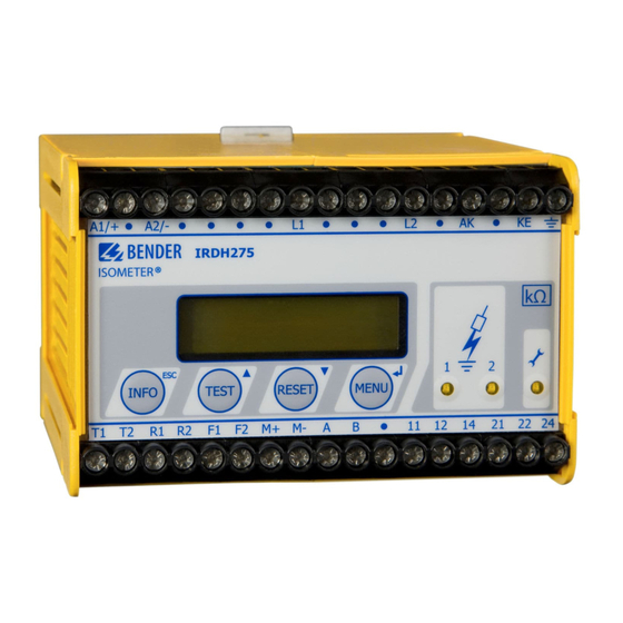
4. Operation and setting 4.1 Operating features and displays IRDH275BU-6 A-ISOMETER® IRDH275 * * * I T - S Y S T E M * * * * R = 0 8 6 k W INFO TEST RESET MENU 1 INFO key: to query standard information / ESC key: back to the menu function, confirmation parameter change 2 TEST button: to call up the self test/ Up key: parameter change, moving up in the menu... -
Page 22: Display In The Standard Mode
Operation and setting 4.1.1 Display in the standard mode I n s u l a t i o n F a u l t R s = 0 1 1 k Indication of the insulation resistance in kΩ 2 Additional information about the insulation resistance: "+"... -
Page 23: Function Keys
Setup status (for details refer to the table of the status numbers on page 53 COM-Setup (own bus address) Please have the details above on hand if you have a problem and if you con- tact BENDER for technical questions. Activating the TEST button starts the A-ISOMETER® self test. TEST... - Page 24 Operation and setting For controlling the menu system, the arrow keys, the ENTER key and the ESC key are used: Arrow up key: Moving up in the menu, increasing a parameter TEST Arrow down key : Moving down in the menu, reducing a parameter RESET ENTER key Selecting a menu item or sub menu item, confirming or storing a...
- Page 25 Operation and setting TGH1384en/06.2005...
-
Page 26: Menu Structure And Menu Mode
Operation and setting 4.2 Menu structure and menu mode Switchover to the menu mode After pressing the MENU key, you can change from the standard mode to the menu mode. From the menu mode you can link to the different sub menus. Navigation within the menu Select the desired menu item using the UP/DOWN keys. -
Page 27: Diagram Menu Structure
Operation and setting 4.2.1 Diagram menu structure *** IT-SYSTEM *** MENU R >010 MW 1. EXIT 2. HISTORY INFO 3. ISO SETUP 4. ISO ADVANCED 5. COM SETUP 6. PASSWORD 7. LANGUAGE 8. SERVICE HISTORY INFO ISO SETUP ISO ADVANCED COM SETUP PASSWORD LANGUAGE... -
Page 28: Menu History Info
Operation and setting 4.3 Menu HISTORY INFO 99 events with date and time stamp can be stored in the memory database. The database is designed as a ring memory, i.e. the eldest entry is overwrit- ten. Data is written into a non-volatile memory and therefore provides pro- tection against voltage failure. -
Page 29: Diagram History Info
Operation and setting 4.3.1 Diagram HISTORY INFO *** IT-SYSTEM *** R >010 MW 1. EXIT 2. HISTORY INFO 3. ISO SETUP 4. ISO ADVANCED 5. COM SETUP 6. PASSWORD 7. LANGUAGE 8. SERVICE Nr.: 01 #Nr: 08 Power on Nr.: 01 #Nr: 08 Clear all: off Nr.: 01 #Nr: 08 Nr.: 02 #Nr: 08... -
Page 30: Menu Iso Setup
Operation and setting 4.4 Menu ISO SETUP: Setting of the basic A-ISOMETER® functions All alarm functions such as Alarm 1 and Alarm 2 (prewarning and main alarm), the operating principle of the alarm relays K1 and K2 (N.O = N/O operation, N.C = N/C operation), the fault storage behaviour and a selection of two current output ranges are set in this menu. - Page 31 Operation and setting Diagram ISO SETUP *** IT-SYSTEM *** R >010 MW 1. EXIT 2. HISTORY INFO 3. ISO SETUP 4. ISO ADVANCED 5. COM SETUP 6. PASSWORD 7. LANGUAGE 8. SERVICE 1. Exit 2. Alarm1: 100 KW Alarm1 : 100 KW 3.
-
Page 32: Memory Setting (On/Off)
Operation and setting During the automatic self test, the alarm relays are not switched over. When a system fault occurs at the A-ISOMETER®, the relay K2 will au- tomatically be activated as a system fault relay . 4.4.3 Memory setting (on/off) Memory: on = Fault memory is activated The device must be reset with the RESET button after... -
Page 33: Menu Iso Advanced: Setting Of The Extended Functions
Operation and setting 4.5 Menu ISO ADVANCED: Setting of the extended functions 4.5.1 Coupling devices AGH: 575S-6 The A-ISOMETER® is connected to the AGH575S-6 by connecting the termi- nal AK to terminal 5. The nominal operating range is extended to AC 0...3.6 kV. -
Page 34: Diagram Iso Advanced
Operation and setting a day at a given time. If the 1 hour auto test has been selected, the self test will be carried out at every full hour. 4.5.8 Diagram ISO ADVANCED *** IT-SYSTEM *** R >010 MW 1. EXIT 2. -
Page 35: Menu Com Setup: Setting The Bms Interface
Operation and setting 4.6 Menu COM SETUP: Setting the BMS interface 4.6.1 Bus address „Addr:“ This menu item is used to set the BMS bus address of the A-ISOMETER®. Since there are several A-ISOMETERs in one system, take care that the bus address is not assigned twice. -
Page 36: Menu Password
Operation and setting 4.7 Menu PASSWORD 4.7.1 Activating and setting the password This menu can be used to activate a "Password" query. This protects the A-ISOMETER® against unauthorized settings and modifications. The desired password (menu item 2. Password: xxx) can be set with the UP/DOWN keys and confirmed with the ENTER key. -
Page 37: Menu Language
Operation and setting 4.8 Menu LANGUAGE 4.8.1 Setting the national language The menu item "Language" allows fault messages of the A-ISOMETER® to be set to different languages. There is the choice of German and English. The device menu is not influenced by the language selection. 4.8.2 Diagram Language *** IT-SYSTEM *** R >010 M... -
Page 38: Menu Service
Operation and setting 4.9 Menu SERVICE This menu item is provided for the BENDER service personnel and is pro- tected by a password against erroneous settings. It is intended to provide fast fault clearance by qualified experts in the event of a device error. -
Page 39: Serial Interfaces
5. Serial interfaces 5.1 RS485 interface with BMS protocol The RS485 interface which is galvanically isolated from the device electronics and current output serves as a physical transmission medium for the BMS protocol. If several A-ISOMETER®s or other bus-capable devices are inter- connected in a network via the BMS bus, the BMS bus must be terminated at both ends with a 120 Ω... -
Page 40: Topology Rs485 Network
(e.g. J-Y(ST)Y 2x0.6), screen on one side connected to earth (PE). Connection to the terminals A and B. The number of bus nodes is restricted to 32 devices. When more devices are to be connected, Bender recommends to use an RS485 repeater DI1. TGH1384en/06.2005... -
Page 41: Bms Protocol
Serial interfaces 5.3 BMS protocol This protocol is an essential part of the Bender Measuring Device Interface. Data transmission generally makes use of ASCII characters. Interface data are: Baud rate: 9600 baud transmission: 1 start bit, 7 data bits, 1 parity bit, 1 stop bit (1, 7, E, 1) -
Page 42: Bms Slave
Serial interfaces Faults may be caused when: addresses are assigned twice a second master exists on the BMS bus interference signals occur on the bus lines a defective device is connected to the bus terminating resistors are not activated 5.3.2 BMS Slave All IRDH275B are factory set to slave mode (address 3). -
Page 43: Commissioning Of An Rs485 Network With Bms Protocol
Serial interfaces The following table gives an overview about essential alarm messages and the assignment of the messages indicated on the display or operator panels, e.g. PRC1470. Message Channel Meaning Insulation Fault Insulation resistance < setting Alarm 1 Insulation Fault Insulation resistance <... - Page 44 Serial interfaces BMS-bus address ranges Addresses* Device Meaning There is no device with address 0 ! Information sent to address 0 applies to all devices connected to the interface (broadcast) PRC1470 Control and indicating device 1...30 IRDH275B/ Insulation monitoring device 375B/575 1...30 FTC470...
-
Page 45: Technical Data Irdh275Bu-6 With Agh575S-6
6. Technical data IRDH275BU-6 with AGH575S-6 6.1 Data in tabular IRDH275BU-6 Insulation coordination acc. to IEC 60664-1 Rated voltage ..........................AC 800 V Rated impulse voltage/pollution degree ..................8 kV / 3 Voltage ranges Nominal voltage range U ....................via AGH575S-6 Supply voltage U (refer to nameplate for other values)............AC 88...264 V Frequency range of U ...................... - Page 46 Technical data IRDH275BU-6 with AGH575S-6 Outputs/inputs TEST/ RESET button......................internal/external Cable length TEST/RESET button external ..................≤ 10 m Ω Current output for measuring instrument SKMP (scale centre point = 1.2 M ): ........Ω Current output (load) ....................20 mA (≤ 500 Ω...
- Page 47 Technical data IRDH275BU-6 with AGH575S-6 Connection, rigid, flexible................0.2...4 mm / 0.2...2.5 mm Connection, flexible with connector sleeve, without/with plastic sleeve..... 0.25...2.5 mm Conductor sizes (AWG)........................24-12 Protection class, internal components (DIN EN 60529) ..............IP30 Protection class, terminals (DIN EN 60529)..................IP20 Type of enclosure....................X112, free from halogen DIN rail mounting ........................
-
Page 48: Data In Tabular Agh575Bu-6
Technical data IRDH275BU-6 with AGH575S-6 6.2 Data in tabular AGH575BU-6 Insulation coordination in consideration of IEC 61800-5-1:2003 Rated voltage..........................AC 3.6 V Voltage test in consideration of IEC 61800-5-1:2003 Rated impulse voltage........................AC 40 kV AC voltage test, duration: 5 s ....................... AC 20 kV Voltage ranges Nominal voltage range U ................AC/3/(N) AC/DC 0...3.6 kV... -
Page 49: Standards And Approvals
Technical data IRDH275BU-6 with AGH575S-6 6.3 Standards and approvals The A-ISOMETER® was designed under consideration of the following standards: - IEC 61557-8:1997-02 - IEC 61326:2002-02 TGH1384en/06.2005... -
Page 50: Characteristic Curves
Technical data IRDH275BU-6 with AGH575S-6 6.4 Characteristic curves Max. AC voltage between IT system and PE in the frequency range of < 50 Hz 10000 IRDH275BU-6 AGH575S-6 1000 f n [Hz] TGH1384en/06.2005... - Page 51 Technical data IRDH275BU-6 with AGH575S-6 Current output 0...20 mA (IRDH275BU-6) [kW] 100 000 10 000 1 000 I [mA] 20 mA x 1200 kW - 1200 kW = Insulation fault in kΩ = Current output in mA TGH1384en/06.2005...
- Page 52 Technical data IRDH275BU-6 with AGH575S-6 Current output 4...20 mA (IRDH275BU-6) [kW] 100 000 10 000 1 000 I [mA] 16 mA x 1200 kW - 1200 kW I - 4 mA = Insulation fault in kΩ = Current output in mA TGH1384en/06.2005...
- Page 53 Technical data IRDH275BU-6 with AGH575S-6 Status number TGH1384en/06.2005...
- Page 54 Technical data IRDH275BU-6 with AGH575S-6 Dimension diagram enclosure IRDH275 ø 4,5 mm DIN rail mounting according to IEC 60715 Screw mounting by means of a plug-in trapezoidal support Order No.: 990056 TGH1384en/06.2005...
- Page 55 Technical data IRDH275BU-6 with AGH575S-6 Dimension diagram enclosure AGH575S-6 220 mm TGH1384en/06.2005...
-
Page 56: Ordering Details
Technical data IRDH275BU-6 with AGH575S-6 6.5 Ordering details 6.5.1 A-ISOMETER® and coupling device Nominal voltage Supply voltage Type Art.-No. AC 88...264 V IRDH275BU-635 B 9106 5111 DC 77...286 V AC/DC 0...3.6 kV AGH575S-6 B 913053 0...460 Hz 6.5.2 Measuring instruments Type Measuring range Dimensions... - Page 57 Alarm LED 1 External coupling devices Alarm LED 2 External RESET button Alarm messages External TEST button Automatic self test Factory setting Bender Measuring Device Interface Flashing point BMS bus Function - correct arrangement Function input F1/F2 - wrong arrangement BMS-bus...
- Page 58 INDEX Operating Operating features and displays Ordering details Parameterization via Internet Product description Real-time clock RESET button RS485 interface Self test, A-ISOMETER Serial interfaces Setting the bus address for IRDH275B Setting the date (IRDH275B) Setting the national language Setting the real-time clock (Clock) Standards Status number system fault LED...
- Page 60 Dipl.-Ing. W. Bender GmbH & Co.KG Londorfer Str. 65 • 35305 Grünberg • Germany Postfach 1161 • 35301 Grünberg • Germany Tel.: +49 (0)6401-807-0 Fax: +49 (0)6401-807-259 E-Mail: info@bender-de.com Internet: http://www.bender-de.com...
Need help?
Do you have a question about the A-ISOMETER IRDH275BU-6 and is the answer not in the manual?
Questions and answers