
Subscribe to Our Youtube Channel
Related Manuals for H3C S3100V2 Series


Summary of Contents for H3C S3100V2 Series
- Page 1 H3C S3100V2 Switch Series Installation Guide Hangzhou H3C Technologies Co., Ltd. http://www.h3c.com Document version: 6W103-20110808...
- Page 2 SecPro, SecPoint, SecEngine, SecPath, Comware, Secware, Storware, NQA, VVG, V G, V G, PSPT, XGbus, N-Bus, TiGem, InnoVision and HUASAN are trademarks of Hangzhou H3C Technologies Co., Ltd. All other trademarks that may be mentioned in this manual are the property of their respective owners Notice The information in this document is subject to change without notice.
- Page 3 Preface The H3C S3100V2 Switch Series Installation Guide guides you through the installation of your switch. It covers product overview, preparing for installation, installing the switch, logging in to the switch, connecting the switch to the network, and troubleshooting. This preface includes: Audience •...
- Page 4 Layer 2 forwarding and other Layer 2 features. Obtaining documentation You can access the most up-to-date H3C product documentation on the World Wide Web at http://www.h3c.com. Click the links on the top navigation bar to obtain different categories of product documentation: [Technical Support &...
-
Page 5: Table Of Contents
Contents Product overview·························································································································································· 1 Switch models····································································································································································1 Panel views ········································································································································································1 S3100V2-26TP-SI/S3100V2-26TP-EI ····················································································································1 S3100V2-16TP-SI/S3100V2-16TP-EI ····················································································································2 S3100V2-8TP-SI/S3100V2-8TP-EI ·························································································································3 S3100V2-26TP-PWR-EI············································································································································4 S3100V2-16TP-PWR-EI············································································································································5 S3100V2-8TP-PWR-EI ··············································································································································6 Preparing for installation ············································································································································· 8 Safety recommendations ··················································································································································8 General safety recommendations ···························································································································8 Safety with electricity ···············································································································································8 ESD prevention ·························································································································································8 Safety with laser ·······················································································································································9 Examining the installation site ·········································································································································9 Temperature requirements ·······································································································································9 Humidity requirements ·············································································································································9... - Page 6 Powering on the switch·················································································································································· 40 Powering on the switch········································································································································· 40 Checking switch boot information ······················································································································· 40 Initially configuring the switch······························································································································ 42 Connecting the switch to the network·······················································································································43 Connecting your switch to the network through twisted pair cables ······························································· 43 Connecting your switch to the network through optical fibers ········································································· 43 Installing an SFP transceiver module ···················································································································...
-
Page 7: Product Overview
Product overview Switch models Table 1 lists the switch models in the H3C S3100V2 Switch Series. Table 1 H3C S3100V2 Switch Series Sub-series Switch models • S3100V2-8TP-SI S3100V2-TP-SI • S3100V2- 1 6TP-SI S3100V2-SI (fanless) • S3100V2-26TP-SI • S3100V2-8TP-EI S3100V2-TP-EI •... -
Page 8: S3100V2-16Tp-Si/S3100V2-16Tp
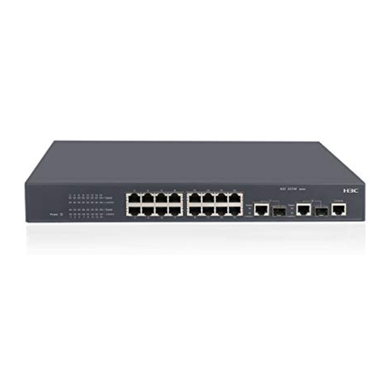
Rear panel Figure 2 S3100V2-26TP-SI/S3100V2-26TP-EI rear panel (1) Grounding screw (2) AC-input power receptacle S3100V2-16TP-SI/S3100V2-16TP-EI Front panel Figure 3 S3100V2-16TP-SI/S3100V2-16TP-EI front panel (1) Speed LED for a 10/100Base-TX Ethernet port (2) 10/100Base-TX Ethernet ports (3) Speed LED for a combo interface (4) Console port (5) Combo interface (10/100/1000Base-T Ethernet port (6) Link/Act LED for a combo interface... -
Page 9: S3100V2-8Tp-Si/S3100V2-8Tp
S3100V2-8TP-SI/S3100V2-8TP-EI Front panel Figure 5 S3100V2-8TP-SI/S3100V2-8TP-EI front panel (1) Speed LED for a 10/100Base-TX Ethernet port (2) 10/100Base-TX Ethernet ports (3) Speed LED for a combo interface (4) Console port (5) Combo interface (10/100/1000Base-T Ethernet port (6) Link/Act LED for a combo interface on the left, 100/1000Base-X SFP port on the right) (7) Link/Act LED for a 10/100Base-TX Ethernet port (8) Power LED... -
Page 10: S3100V2-26Tp-Pwr
S3100V2-26TP-PWR-EI Front panel Figure 7 S3100V2-26TP-PWR-EI front panel (1) 10/100Base-TX Ethernet port (2) 10/100Base-TX Ethernet port LEDs (left: yellow, right: green) (3) Combo interface (10/100/1000Base-T Ethernet (4) LINK LED for a combo interface port on the left, 100/1000Base-X SFP port on the right) (5) Console port (6) Port LED mode switching (Mode) button (7) Power (PWR) LED... -
Page 11: S3100V2-16Tp-Pwr
S3100V2-16TP-PWR-EI Front panel Figure 9 S3100V2-16TP-PWR-EI front panel (1) 10/100Base-TX Ethernet port (2) 10/100Base-TX Ethernet port LEDs (left: yellow, right: green) (3) Combo interface (10/100/1000Base-T Ethernet (4) LINK LED for a combo interface port on the left, 100/1000Base-X SFP port on the right) (5) Console port (6) Port LED mode switching (Mode) button (7) Power (PWR) LED... -
Page 12: S3100V2-8Tp-Pwr
S3100V2-8TP-PWR-EI Front panel Figure 11 S3100V2-8TP-PWR-EI front panel (1) 10/100Base-TX Ethernet port (2) 10/100Base-TX Ethernet port LEDs (left: yellow, right: green) (3) Combo interface (10/100/1000Base-T Ethernet (4) LINK LED for a combo interface port on the left, 100/1000Base-X SFP port on the right) (5) Console port (6) Port LED mode switching (Mode) button (7) Power (PWR) LED... - Page 13 Figure 13 S3100V2-8TP-PWR-EI right side panel (1) Security lock slot...
-
Page 14: Preparing For Installation
Preparing for installation Safety recommendations To avoid possible bodily injury and equipment damage, read the safety recommendations in this chapter carefully before installing an S3100V2 switch. The recommendations do not cover every possible hazardous condition. General safety recommendations Keep the chassis clean and dust-free. Do not clean the switch with wet cloth or liquid. •... -
Page 15: Safety With Laser
Figure 14 Use an ESD-preventive wrist strap (1) Rack post Safety with laser The S3100V2 Switch Series is a line of class 1 laser products. When a transceiver module on an S3100V2 switch is operating, do not stare into the optical port because the laser light emitted from the optical fiber may hurt your eyes. -
Page 16: Cleanness Requirements
Table 3 Humidity requirements Humidity Range Operating humidity (noncondensing) 10% to 95% Storage humidity (noncondensing) 5% to 95% Lasting high relative humidity tends to cause poor insulation, electricity creepage, mechanical property change of materials, and corrosion of metal parts. Lasting low relative humidity is likely to result in loose screws due to washer contraction, and even electrostatic discharge (ESD), which causes the circuits to fail. -
Page 17: Grounding Requirements
Keep the switch far away from high-power radio launchers, radars, and equipment with high • frequency or high current. • Use electromagnetic shielding, for example, shielded interface cables, when necessary. Route interface cables only indoors to prevent signal ports from getting damaged by over-voltage •... -
Page 18: Installation Tools
Installation tools Table 6 Tool list Category Tool Measuring and marking tools Long tape, ruler of 1 m (3.28 ft), gradienter, marker, chalk line, and pencil Drills Percussion drill, electric drill, and several auxiliary drill bits Flat-blade screwdriver P4-75 mm Phillips screwdriver P1-100 mm, P2-150 mm, and P3-250 mm Fastening tools Socket wrench M5... -
Page 19: Installing The Switch
Keep the tamper-proof seal on a mounting screw on the chassis cover intact, and if you want to open the chassis, contact the local agent of H3C for permission. Otherwise, H3C shall not be liable for any consequence caused thereby. -
Page 20: Installation Accessories
Table 7 S3100V2 Switch Series installation methods Switch model Installation methods Installation accessories 1. Installing the switch into the 19-inch rack • Rack mounting by using front mounting Front mounting bracket. See callout A brackets Figure 17 (supplied). • Rack mounting by front mounting S3100V2-26TP-SI Support tray: User supplied brackets and a support tray... - Page 21 Figure 17 Front mounting brackets (1) Screw hole (for M6 screw) for fixing the front mounting bracket to the rack (2) Screw hole for fixing the front mounting bracket to the switch (3) M4 screws for fixing the front mounting bracket to the switch Figure 18 Rear mounting bracket (1) Screw hole (for M6 screw) for fixing the rear mounting bracket to the rack (2) Load-bearing screw (installed to the switch)
- Page 22 (4) M5 self-tapping screws for fixing the slide rail to the rack NOTE: Slide rails purchased from H3C apply only to standard racks with a depth of 1000 mm (39.37 in). Use other supports to substitute for slide rails in case of other rack depths.
- Page 23 (3) M4 screws for fixing the mounting bracket to the switch To mount the switch to a wall, H3C recommends you to use M6 expansion anchors. An expansion anchor comprises anchor rod, anchor sleeve, flat washer, spring washer, and hex nut.
-
Page 24: Installing The Switch Into The 19-Inch Rack
Installing the switch into the 19-inch rack CAUTION: Ensure a clearance of 1U (44.45 mm, or 1.75 in) between equipment for heat dissipation. • For a switch with the depth greater than 300 mm (1 1.81 in), the front mounting brackets only secure the •... - Page 25 Figure 25 Mount the switch to the rack by using front mounting brackets (1) Front rack posts (2) Switch front panel (3) Front mounting bracket Rack mounting by front mounting brackets and a support tray Follow these steps to mount the switch to the rack by front mounting brackets and a support tray: Wear an ESD-preventive wrist strap and make sure it makes good skin contact and is well grounded, Step1 check that the rack is sturdy and well grounded.
- Page 26 Unpack the load-bearing screws (packed with the rear mounting brackets), and install them to the Step4 appropriate positions on the two sides of the switch, as shown in Figure Figure 26 Rack mounting by using front and rear mounting brackets (1) Load-bearing screw (2) Load-bearing screw positions (select one as needed)
- Page 27 Figure 27 Mount the switch to the rack by using rear mounting brackets (1) Rack posts (2) Rear mounting bracket CAUTION: Make sure the thinner edge of the rear mounting bracket faces upwards to ensure that the mounting bracket can make close contact with the load-bearing screws. Supporting the switch bottom with one hand, use the other hand to push the switch into the rack until the Step7 load-bearing screws on the switch make close contact with the upper edge of the rear mounting bracket,...
- Page 28 Figure 28 Mount the switch to the rack by using front and rear mounting brackets (1) Switch rear panel (2) Rear rack post (3) Load-bearing screw (4) Rear mounting bracket Have another person to fix the front mounting brackets to the front rack posts by using the M6 screws, Step8 making sure that the front and rear mounting brackets can fix the switch steadily into the rack, as shown Figure...
- Page 29 Figure 29 Mount the switch to the rack by using front and rear mounting brackets (1) Load-bearing screw (2) Rear mounting bracket (3) Switch front panel (4) M6 screw for fix the front mounting bracket to the rack (5) Front mounting bracket (6) Front rack post Rack mounting by using front mounting brackets and slide rails Follow these steps to mount the switch to the rack by using front mounting brackets and slide rails:...
-
Page 30: Mounting The Switch On A Workbench
Figure 30 Install the slide rails Supporting the switch bottom, slide the switch along the slide rails into the rack until the lower edges of Step5 the slide rails make close contact with the switch bottom. Then use the M6 screws to fix the front mounting brackets to the front rack posts, as shown in Figure Figure 31 Mount the switch to the rack by using front mounting brackets and slide rails... -
Page 31: Mounting The Switch On A Wall
During the operation, note the following guidelines: • Make sure that the workbench is flat and sturdy. Ensure good ventilation and a space of 10 cm (3.94 in) around the chassis for heat dissipation. • Avoid heavy objects on the switch. •... - Page 32 Insert the expansion anchors into the holes, and remove the hex nut, spring washer, and flat washer from Step3 each expansion anchor, as shown in Figure Figure 34 Install an expansion anchor Supporting the switch with the network ports facing downwards, insert the mounting brackets into the Step4 four expansion anchors.
-
Page 33: Magnet Mounting
Magnet mounting The S3100V2-8TP-PWR-EI supports magnet mounting. Follow these steps to complete magnet mounting: As shown in Figure 36, use a Phillips screwdriver to pass the countersunk head screw through the round Step1 hole at the center of the magnet, fasten it to a blind nut in the dent of the switch bottom, and make sure that the magnet and the switch are closely fastened. -
Page 34: Grounding The Switch
Grounding the switch CAUTION: Before using the switch, connect the grounding cable properly to guarantee lightning protection and • anti-interference of the switch. The power interface and grounding terminals in this section are for illustration only. • The power input end of the switch has a noise filter, whose central ground is directly connected to the chassis to form the chassis ground. - Page 35 CAUTION: The supplied grounding cable of the S3100V2 Switch Series does not have an auxiliary OT terminal. • Connect the grounding cable to the earthing system in the equipment room. Do not connect it to a fire • main or lightning rod. Connecting the grounding cable to the switch Follow these steps to connect the grounding cable to the switch: Remove the grounding screw on the rear panel of the switch.
-
Page 36: Grounding The Switch With A Grounding Conductor Buried In The Earth Ground
part.Connect the made connector to the grounding post of the grounding strip, and then fasten it with a hex nut, as shown in Figure Figure 39 Make the grounding cable connector Figure 40 Connect the grounding cable to a grounding strip (1) Grounding post (2) Grounding strip (3) grounding cable... -
Page 37: Grounding The Switch With The Pe Wire Of An Ac Power Supply
CAUTION: Hammer a 0.5 m (1.64 ft) or longer angle iron or steel tube into the earth. The angle iron should have a dimension no less than 50 × 50 × 5 mm (1.97 × 1.97 × 0.20 in) and the steel tube should have a wall thickness no less than 3.5 mm (0.14 in) and be zinc-coated. -
Page 38: Connecting The Power Cord
Figure 42 Ground the switch through the PE wire of the AC power supply (1) Three-wire AC power input cable (2) Switch rear panel Connecting the power cord CAUTION: Before powering on the switch, you must connect the power cord and make sure the switch is well grounded. -
Page 39: Connecting The Dc Power Cord
The positions of bail latch slots on the switch depend on your switch model. Connecting the DC power cord The S3100V2-26TP-PWR-EI/S3100V2- 1 6TP-PWR-EI provides a DC power receptacle as shown in Figure 46. You can use the –48 VDC power in the equipment room or the H3C RPS DC power input. -
Page 40: Verifying The Installation
Figure 46 DC power receptacle +: Chassis ground —: Input voltage range (–47 VDC to –57 VDC) NULL: Reserved Follow these steps to connect the DC power cord: Wear an ESD-preventive wrist strap and make sure it makes good skin contact and is well grounded. Step1 Insert the power cord with the plug upside up. - Page 41 All the interface cables are cabled indoors. If there is any cable wired outdoors, verify that socket • strip with lightning protection and lightning arresters for network ports have been properly connected.
-
Page 42: Logging In To The Switch
Logging in to the switch You can log in only through the console port when you log in to your switch for the first time. Preparations before login Make the following preparations before logging in to the switch for the first time: Table 9 Preparations before login Task Description... -
Page 43: Setting Up A Configuration Environment
RJ-45 Signal DB-9 DB-9 Setting up a configuration environment To set up the configuration environment, connect a terminal (a PC in this example) to the console port on the switch with a console cable, as shown in Figure Follow these steps to connect a terminal device to the switch using the console cable: Plug the DB-9 female connector of the console cable to the serial port of the console or PC. - Page 44 Follow these steps to set terminal parameters: Select Start > All Programs > Accessories > Communications > HyperTerminal to enter the Step1 HyperTerminal window. The Connection Description dialog box appears, as shown in Figure Figure 50 Connection description of the HyperTerminal Type the name of the new connection in the Name text box and click OK.
- Page 45 Figure 52 Set the serial port parameters Click OK after setting the serial port parameters and the system enters the following interface. Step4 Figure 53 HyperTerminal window...
-
Page 46: Powering On The Switch
Click Properties in the HyperTerminal window to enter the Switch Properties dialog box. Click the Step5 Settings tab, set the emulation to VT100, and then click OK. Figure 54 Set terminal emulation in Switch Properties dialog box Powering on the switch Powering on the switch Before powering on the switch, check the following items: The switch is sturdy. - Page 47 The output information varies depending on the software version. • Starting..************************************************************************ H3C S3100V2-26TP-PWR-EI BOOTROM, Version 107 ************************************************************************ Copyright(c) 2004-2011 Hangzhou H3C Technologies Co., Ltd. Creation Date : Jan 19 2011,10:54:47 CPU Clock Speed : 200MHz Memory Size : 128MB...
-
Page 48: Initially Configuring The Switch
Divides the network into multiple VLANs, and improves data security. MSTP Avoids loops in a network using dual uplinks to provide redundancy. NOTE: H3C S3100V2 For more information about login methods and access function configuration, see the Switch Series Configuration Guides... -
Page 49: Connecting The Switch To The Network
Connecting the switch to the network NOTE: H3C recommends that you perform basic configuration for your switch before connecting it to the network. Connecting your switch to the network through twisted pair cables The 10/100/1000Base-T ports of the H3C S3100V2 Switch Series use RJ-45 connectors and support MDI/MDI-X auto-sensing. -
Page 50: Installing An Sfp Transceiver Module
Installing an SFP transceiver module NOTE: This section only briefly describes the installation and operation guidelines for an SFP transceiver module. H3C Pluggable SFP/SFP+/XFP Transceiver Modules Installation Guide For more information, see the Follow these steps to install an SFP transceiver module: Wear an ESD-preventive wrist strap and make sure it makes good skin contact and is well grounded. - Page 51 SFP port, you must use the combo enable fiber command to activate the SFP port. After connecting the switch to the network, you can use the ping or tracert command to check the • H3C S3100V2 interoperability between the switch and the network. For more information, see the Switch Series Command References If the port status LED on the switch flashes after you connect the switch to the network, and the switch •...
-
Page 52: Troubleshooting
Troubleshooting TIP: Clean your switch periodically because the noncompliant operating environments of switches may cause switch failures. At the same time, check the installation environments against the requirements in “Preparing for installation.” Make sure the switch operates in a proper environment. Additionally, periodically perform the power-on test for the spare switches. -
Page 53: Troubleshooting Interfaces
Check the power supply system. Make sure that the power supply system works properly and outputs a Step2 voltage required by the switch. If the failure still exists, contact the local agents or technical support engineers. Step3 Troubleshooting interfaces Each interface has a corresponding LED. When an interface connected to the network works properly, the corresponding LINK LED is on. -
Page 54: Troubleshooting Software Loading
Check the temperature of the switch. The S3100V2-TP-PWR-EI Switch Series provides the overtemperature Step3 protection mechanism. When the internal temperature of the switch exceeds 65°C (149°F), the switch performs self protection and disables PoE on all ports. When the internal temperature drops below 60°C (140°F), the switch enables PoE on all ports. -
Page 55: Appendix A Technical Specifications
Appendix A Technical specifications S3100V2-SI Switch Series technical specifications Table 13 S3100V2-SI switches technical specifications Item S3100V2-26TP-SI S3100V2-16TP-SI S3100V2-8TP-SI Dimensions (H × W 43.6 × 440 × 160 mm 43.6 × 360 × 160 mm 43.6 × 230 × 160 mm ×... -
Page 56: S3100V2-Ei Switch Series Technical Specifications
S3100V2-16TP-SI S3100V2-8TP-SI Chassis leakage UL60950-1, EN60950-1, IEC60950-1, GB4943 current compliance S3100V2-EI Switch Series technical specifications The H3C S3100V2-EI Switch Series includes the S3100V2-TP-EI switches and the S3100V2-TP-PWR-EI switches. S3100V2-TP-EI switches technical specifications Table 14 S3100V2-TP-EI switches technical specifications Item S3100V2-26TP-EI... -
Page 57: S3100V2-Tp-Pwr-Ei Switches Technical Specifications
DC-input You can connect the switch chassis to a –48 VDC power source or an H3C external RPS. For the RPSs available for RPS Ordering the switches and their specifications, see the Guide for H3C Low-End Series Ethernet Switches and their respective user manuals. - Page 58 Item S3100V2-26TP-PWR-EI S3100V2-16TP-PWR-EI S3100V2-8TP-PWR-EI Total PoE output 370 W 250 W 125 W power Power consumption (minimum hardware 20 W 20 W 16 W and software configuration) Power consumption (full hardware AC: 465 W AC: 300 W configuration, all PoE 155 W DC: 400 W DC: 273 W...
-
Page 59: Appendix B Ports And Leds
Appendix B Ports and LEDs Ports Console port All S3100V2 switches have one console port on the front panel. Table 17 Console port specifications Item Specification Connector type RJ-45 Compliant standard Asynchronous EIA/TIA-232 Transmission baud rate 9600 bps (default) to 115200 bps •... -
Page 60: 10/100/1000Base-T Ethernet Port
All S3100V2 switches provide 100/1000Base-X SFP ports on their front panels, and you can install the hot swappable 100 Mbps or 1000 Mbps SFP transceiver modules in Table 20 in the ports for long distance connections. Table 20 SFP transceiver modules available for the H3C S3100V2 Switch Series Central Category Transceiver module Connector... -
Page 61: Leds
UTP/STP transceiver modules NOTE: To guarantee the functionality of the SFP ports, always use H3C SFP transceiver modules on the H3C • S3100V2 Switch Series. • The SFP-STACK-Kit module is dedicated for connecting switches and has connected to a 1.5 m (4.92 ft) cable. -
Page 62: Leds On The S3100V2-Tp-Pwr-Ei Switches
Table 22 Power LED on the S3100V2-TP-SI/S3100V2-TP-EI switches Status Description Steady green The switch is powered on. Power The switch is powered off or has a power supply problem. 10/100Base-TX Ethernet port LEDs The 10/100Base-TX Ethernet port LEDs show the presence of link, data transmission status, and rate of a 10/100Base-TX Ethernet ports. - Page 63 Table 25 Power LED on the S3100V2-TP-PWR-EI switches Status Description Steady green The switch is powered on. The switch is powered off or has a power supply problem. Port mode LEDs The A/L and D/S port mode LEDs on the S3100V2-TP-PWR-EI switches show the type of information that the 10/100Base-TX port LEDs are displaying as in Table 26.
- Page 64 Combo interface LEDs The combo interface LEDs show the presence of link, data transmission status, and port rate of a combo interface. Table 28 Combo interface LEDs on the S3100V2-TP-PWR-EI switches Status Description Steady green A link is present on the interface. LINK No link is present on the interface.
-
Page 65: Appendix C Ethernet Twisted Pair Cable
Appendix C Ethernet twisted pair cable Ethernet twisted pair cable An Ethernet twisted pair cable consists of four pairs of insulated wires twisted together. It mainly transmits analog signals and is advantageous in transmitting data over shorter distances. The maximum transmission distance is 100 m (328.08 ft). - Page 66 Table 29 Description on commonly used Ethernet cables Type Description Suitable for data transmission at a maximum speed of 100 Mbps, with a bandwidth Category 5 of 100 MHz. Suitable for data transmission at a maximum speed of 1000 Mbps, with a Category 5e bandwidth of 100 MHz.
-
Page 67: Pin Assignments
Figure 61 Crossover cable white/orange orange white/green blue white/blue green white/brown brown Crossover cable white/green green white/orange blue white/blue orange white/brown brown Pin assignments Select an Ethernet twisted pair cable according to the RJ-45 Ethernet interface type on your device. An RJ-45 Ethernet interface can be MDI (for routers and PCs) or MDIX (for switches). -
Page 68: Making An Ethernet Twisted Pair Cable
10Base-T/100Base-TX 1000Base-T Signal Function Signal Function Send data BIDA+ Bi-directional data cable A+ Reserved — BIDD+ Bi-directional data cable D+ Reserved — BIDD- Bi-directional data cable D- Send data BIDA- Bi-directional data cable A- Reserved — BIDC+ Bi-directional data cable C+ Reserved —... -
Page 69: Index
Index C E G I L P S T V Ports,53 Powering on the switch,40 Connecting the power cord,32 S3100V2-EI Switch Series technical specifications,50 Ethernet twisted pair cable,59 S3100V2-SI Switch Series technical specifications,49 Examining the installation site,9 Safety recommendations,8 Switch models,1 Grounding the switch,28...
Need help?
Do you have a question about the S3100V2 Series and is the answer not in the manual?
Questions and answers