Table of Contents
Advertisement
Available languages
Available languages
Quick Links
Advertisement
Chapters
Table of Contents

Related Manuals for TE Connectivity AT-SC


Summary of Contents for TE Connectivity AT-SC
- Page 1 Mode d’Emploi Betriebsanleitung Operating Instructions Pneum. Parallel Pneum. Parallel Machine Pneum. à Crimpmaschine Crimp Machine Sertir Parallèle AT-SC AT-SC AT-SC P/N 528050-1 P/N 528050-1 P/N 528050-1 412-18876 / 5-744013-6 30.06.2016, Rev. G Page 1 / 101 ECOC: EGC0 ; LOC: AI...
- Page 2 Table of contents ............................36 Version Française Table des matières ........................... 69 Vertrieb / Sale / Vente Tyco Electronics AMP GmbH a TE Connectivity Ltd. Company Amperestr. 12-14 D-64625 Bensheim Deutschland Page 2 / 101 ECOC: EGC0 ; LOC: AI...
-
Page 3: Table Of Contents
528050-1 412-18876 Rev. G Inhaltsverzeichnis Bedienungsanleitung ..........................5 Umgang mit der Betriebsanleitung ....................5 Sicherheitshinweise in der Betriebsanleitung ................5 Grundlegende Sicherheitshinweise ...................... 6 Zuständigkeit ..........................6 Hinweise zum Einrichten und Betreiben der Maschine ..............6 Hinweise zum Warten und Instandhalten der Maschine..............6 Allgemeine Angaben/Produktbeschreibung/Funktion ................ - Page 4 528050-1 412-18876 Rev. G 15 Lagerung ............................. 26 16 Entsorgung ............................26 17 Ersatzteilliste, Pneumatikschema, Elektroschema ................27 17.1 Explosionszeichnung ........................ 27 17.2 Stückliste Explosionszeichnung ....................28 17.3 Pneumatik Schema ........................32 17.4 Stückliste Pneumatik Schema ....................33 17.5 Pneumatik Schema Doppelfußpedal ..................34 17.6 Elektro Schema ........................
-
Page 5: Bedienungsanleitung
Er muss während der Durchführung von Arbeiten an oder mit der Maschine diese Betriebsanleitung beachten. Die Firma TE Connectivity lehnt jede Haftung für Schaden ab, der durch Nichtbeachten von Hinweisen auf der Maschine oder in der Betriebsanleitung entsteht. Die Betriebsanleitung ist vom Benutzer der Maschine um Anweisungen aufgrund bestehender nationaler Vorschriften zur Unfallverhütung und zum Umweltschutz zu ergänzen. -
Page 6: Grundlegende Sicherheitshinweise
528050-1 412-18876 Rev. G Grundlegende Sicherheitshinweise Die Pneum. Parallel Crimpmaschine AT-SC ist nach dem Stand der Technik und den anerkannten sicherheitstechnischen Regeln gebaut. Beim Ausführen von Arbeiten, wie Aufstellen, Inbetriebnahme, Einrichten, Betreiben, Ändern der Einsatzbedingungen und Betriebsweisen, Warten und Instandhalten der Maschine, sind die in der Betriebsanleitung vorgeschriebenen Ausschaltprozeduren zu beachten. -
Page 7: Allgemeine Angaben/Produktbeschreibung/Funktion
Pneum. Parallel Crimpmaschine AT-SC und dem auswechselbaren TE Crimpwerkzeug-System verarbeitet. Jede andere Einsatzart der Pneum. Parallel Crimpmaschine AT-SC ist nur mit schriftlicher Zustimmung des Herstellers zulässig. Jede nicht bewilligte Einsatzart der Pneum. Parallel Crimpmaschine AT-SC gilt als nicht bestimmungsgemäß. Für daraus resultierende Schäden lehnt der Hersteller jede Haftung ab. -
Page 8: Sicherheit
Zum Herstellen von Crimpverbindungen bis zu einem Leitungsquerschnitt von max. 50mm² in Abhängigkeit der Terminalausführung Die Pneum. Parallel Crimpmaschine AT-SC ist zur Aufnahme der in Kapitel 12 dargestellten Adapter konzipiert. Die Adapter dürfen nur mit den TE spezifizierten Crimpgesenken bestückt werden. Die Pneum. -
Page 9: Gefährdungsbereich
Quetschens von Fingern. Versuchen Sie nie, in das Werkzeug zu greifen, ohne dass die Maschine sicher von der pneumatischen Versorgung getrennt wurde. Ändern Sie die Pneum. Parallel Crimpmaschine AT-SC nicht ab und setzen Sie sie nur für den vorgesehenen Verwendungszweck ein. -
Page 10: Lieferung
GEFAHR! Für den Transport muss ein ausreichend dimensioniertes Hebezeug verwendet werden. Lieferumfang 1 Stk. Pneum. Parallel Crimpmaschine AT-SC mit Stückzähler, Manometer und Betriebsanleitung 1 Stk. SDE Adapter (Standardadapter) 1 Stk. Pneum. Doppelfußpedal mit Schutzhaube 1 Stk. Werkzeugsatz (Stiftschlüssel 2,0 / 2,5mm ) 1 Stk. -
Page 11: Technische Beschreibung
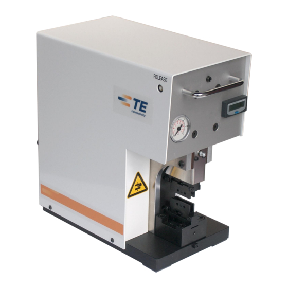
528050-1 412-18876 Rev. G Technische Beschreibung Funktions- und Bedienungselemente Abb. 6.01 Abb. 6.02 Pos. Bezeichnung Pneum. Parallel Crimpmaschine AT-SC Einstellschraube Schmiernippel Obere Gesenkaufnahme Untere Gesenkaufnahme Klemmschraube (Höhe) Klemmschraube (Schaft) Gesenkadapter Gesenkeinsatz Rückstell-Taster Stückzähler Manometer Pneum. Anschlüsse Geschw. Vorverpressung Druckregler Vorverpressung Pneum. -
Page 12: Technische Daten
62 dB(A) Rückstell-Taster Sind die Crimpbacken durch einen Bedienungs- oder Handhabungsfehler oder falsches Einlegen eines Presskabelschuhes blockiert, wird die Pneum. Parallel Crimpmaschine AT-SC wie folgt gelöst: Trennen Sie die Maschine vom Druckluftnetz Betätigen Sie den Rückstell-Taster Abb. 6.03 Transport und Aufstellung Transport Die Masse der Maschine beträgt 22 kg. -
Page 13: Aufstellung
528050-1 412-18876 Rev. G Aufstellung HINWEIS: Um das Betriebsgeräusch zu vermindern, können Sie die Crimpmaschine auf eine rutschfeste Gummiunterlage stellen. VORSICHT! Stellen Sie die Crimpmaschine auf einer ebenen Fläche auf und sorgen Sie für Standfestigkeit der Crimpmaschine. Stellen Sie sicher, dass die Fläche stark genug ist, um das Gewicht der Maschine bei normaler Benutzung aufnehmen zu können ... -
Page 14: Inbetriebnahme
Die Crimpmaschine darf nur in einem vollständigen und funktionsfähigen Zustand betrieben werden. Tragen Sie beim Arbeiten mit der Pneum. Parallel Crimpmaschine AT-SC keine lose Kleidung, losen Schmuck oder lange, offene Haare, welche sich in den Teilen der Pneum. Parallel Crimpmaschine AT-SC verfangen können. -
Page 15: Maschineneinstellung Des Electronics Crimpwerkzeug System
Die Pneum. Parallel Crimpmaschine AT-SC nur mit aufbereiteter (geölter und gereinigter) Druckluft betreiben. Standardfilter: 30 µm. Anschluss Air MAX. (Abb. 8.01, Pos. 1) der Pneum. Parallel Crimpmaschine AT-SC mit Druckluft- schlauch Ø 8/6 mm mit dem Druckluftnetz verbinden. Betriebsdruck: 6 bar WARNUNG! ... - Page 16 Die Crimpmaschine darf nur in einem vollständigen und funktionsfähigen Zustand betrieben werden. Tragen Sie beim Arbeiten mit der Pneum. Parallel Crimpmaschine AT-SC keine lose Kleidung, losen Schmuck oder lange, offene Haare, welche sich in den Teilen der Pneum. Parallel Crimpmaschine AT-SC verfangen können.
-
Page 17: Umrüsten
Die Crimpmaschine darf nur in einem vollständigen und funktionsfähigen Zustand betrieben werden. Tragen Sie beim Arbeiten mit der Pneum. Parallel Crimpmaschine AT-SC keine lose Kleidung, losen Schmuck oder lange, offene Haare, welche sich in den Teilen der Pneum. Parallel Crimpmaschine AT-SC verfangen können. -
Page 18: Gesenkemontage
Die Crimpmaschine darf nur in einem vollständigen und funktionsfähigen Zustand betrieben werden. Tragen Sie beim Arbeiten mit der Pneum. Parallel Crimpmaschine AT-SC keine lose Kleidung, losen Schmuck oder lange, offene Haare, welche sich in den Teilen der Pneum. Parallel Crimpmaschine AT-SC verfangen können. -
Page 19: Einschubvorrichtung (P/N 528052-1) (Optionales Accessoire Für Wdt Adapter)
Die Crimpmaschine darf nur in einem vollständigen und funktionsfähigen Zustand betrieben werden. Tragen Sie beim Arbeiten mit der Pneum. Parallel Crimpmaschine AT-SC keine lose Kleidung, losen Schmuck oder lange, offene Haare, welche sich in den Teilen der Pneum. Parallel Crimpmaschine AT-SC verfangen können. -
Page 20: Normalbetrieb /Produktionsbetrieb
Die Crimpmaschine darf nur in einem vollständigen und funktionsfähigen Zustand betrieben werden. Tragen Sie beim Arbeiten mit der Pneum. Parallel Crimpmaschine AT-SC keine lose Kleidung, losen Schmuck oder lange, offene Haare, welche sich in den Teilen der Pneum. Parallel Crimpmaschine AT-SC verfangen können. -
Page 21: Bedienung Des Doppelfußpedals
528050-1 412-18876 Rev. G VORSICHT! Das Doppelfußpedal muss auf den Boden gestellt werden. Jede andere Platzierung des Doppelfußpedals als auf dem Fußboden ist untersagt. Das Doppelfußpedal muss verschoben werden können, damit der Bediener seine Position wechseln kann und weniger schnell ermüdet. Doppelfußpedal nicht in Verkehrswegen verlegen. -
Page 22: Auswechselbare Gesenkadapter
528050-1 412-18876 Rev. G Auswechselbare Gesenkadapter SDE Die Holder (Standardadapter) TE P/N 1-528051-0 Abb. 11.01 PEZ 100 Die Holder TE P/N 1-528051-2 Abb. 11.02 ERGO Die Holder TE P/N 1-528051-6 Abb. 11.03 Page 22 / 101 ECOC: EGC0 ; LOC: AI... -
Page 23: Instandhaltung
Trennen Sie die Pneum. Parallel Crimpmaschine AT-SC vom Druckluftnetz, bevor Sie irgendwelche Wartungs- oder Demontagearbeiten vornehmen. Tragen Sie beim Arbeiten mit der Pneum. Parallel Crimpmaschine AT-SC keine lose Kleidung, losen Schmuck oder lange, offene Haare, welche sich in den Teilen der Pneum. -
Page 24: 12.1.1 Täglich
Grobe Verschmutzung und Abrieb absaugen. 12.1.1 Täglich Optische Kontrolle Pneum. Parallel Crimpmaschine AT-SC Kontrolle Druckluft 6 bar /90 PSI 12.1.2 Monatlich Schmieren des Crimpstössels durch Schmiernippel und mitgelieferte Stoßdruckpresse (Abb. 12.01) mit Blaser Swiss Lube Art.-Nr. 00492-01 EP-Universal Fett (1 Stoßdruck) Abb. -
Page 25: Fehlersuche Und Störungsanalyse
Maschine entfernt werden. Insbesondere Gehäuse und Abdeckungen dürfen nur von fachkundigem Personal entfernt werden. Tragen Sie beim Arbeiten mit der Pneum. Parallel Crimpmaschine AT-SC keine lose Kleidung, losen Schmuck oder lange, offene Haare, welche sich in den Teilen der Pneum. -
Page 26: Außerbetriebnahme, Abbau, Demontage
Die Crimpmaschine darf ausschließlich bei montiertem Gesenkadapter außerbetrieb genommen werden. Lagerung Maschine bei Raumtemperatur in der Originalkiste lagern. Entsorgung Zur Entsorgung der Pneum. Parallel Crimpmaschine AT-SC, ist diese an TE zurück zu liefern. Page 26 / 101 ECOC: EGC0 ; LOC: AI... -
Page 27: Ersatzteilliste, Pneumatikschema, Elektroschema
528050-1 412-18876 Rev. G Ersatzteilliste, Pneumatikschema, Elektroschema 17.1 Explosionszeichnung Abb. 17.01 Page 27 / 101 ECOC: EGC0 ; LOC: AI... -
Page 28: Stückliste Explosionszeichnung
528050-1 412-18876 Rev. G 17.2 Stückliste Explosionszeichnung Pos.-Nr. Stück TE-P/N Ersatzteil Bezeichnung 5-523795-0 Grundplatte (1296-03) 5-523795-1 Umlenkhebel (1296-06) 5-523795-2 Querwelle (1296-11) 5-523795-3 Gelenkflansch (1296-12) 5-523795-4 Frontblech links (1296-14) 5-523795-5 Frontblech rechts (1296-15) 5-523795-6 Seitenwand (1296-01) 5-523795-7 Endschalterwinkel (1296-16) 5-523795-8 Endschalterfahne (1296-17) 5-523795-9 Gelenkwelle (1296-18) 6-523795-0... - Page 29 528050-1 412-18876 Rev. G Pos.-Nr. Stück TE-P/N Ersatzteil Bezeichnung 8-523795-0 Endschalterplatte (1296-26 BA) 2-519000-0 Zylinderschraube mit Iskt. M4x8 DIN912 4-519000-2 Zylinderschraube mit Iskt. M6x16 DIN912 4-519000-7 Zylinderschraube mit Iskt. M6x40 DIN912 4-519000-4 Zylinderschraube mit Iskt. M6x25 DIN912 1-519000-4 Zylinderschraube mit Iskt. M3x12 DIN912 1-519000-5 Zylinderschraube mit Iskt.
- Page 30 528050-1 412-18876 Rev. G Pos.-Nr. Stück TE-P/N Ersatzteil Bezeichnung 6-519011-0 Gewindestift mit Iskt. DIN913-M8x45 3-519000-6 Zylinderschraube mit Iskt. DIN912-M5x35 519040-3 Federring DIN 127-A4 9-523795-0 Pass-Schulterschraube Ø6/M5x10 2-523781-6 O-Ring DIN 3771 - 25 x 2 2-519052-7 Zylinderstift DIN 6325 - 10 x 24 9-523795-1 Pass-Schulterschraube Ø8/M6x16 9-523795-2...
- Page 31 528050-1 412-18876 Rev. G Pos.-Nr. Stück TE-P/N Ersatzteil Bezeichnung 523796-9 ODER-Ventil 1-523781-9 Gesenkauflage (1296-10) 1-523781-8 Klemmschraube unten (1296-31) 1-523781-7 9-Lochmutter (1296-32) 1-523781-6 Seitenplatte (1296-25) 3-519000-1 Zylinderschraube mit Iskt. M5x12 DIN912 1-519013-4 Gewindestift mit Iskt. M3x6 DIN915 1-523796-0 Kugel 3,0mm 3-519011-5 Gewindestift mit Iskt.
-
Page 32: Pneumatik Schema
528050-1 412-18876 Rev. G 17.3 Pneumatik Schema Abb. 17.02 Page 32 / 101 ECOC: EGC0 ; LOC: AI... -
Page 33: Stückliste Pneumatik Schema
528050-1 412-18876 Rev. G 17.4 Stückliste Pneumatik Schema Pos. Stück TE-P/N Ersatzteil Bezeichnung Pneum. Zylinder 63/50 6-523781-9 5/2-Wege Ventil K52DP218 7-523781-5 Oder-Ventil 4mm OR42 13/a 7-523781-1 Micro-Switch Kuhnke 72.020 13/b 7-523781-3 Schalter Rückhub 72.010 13/b 7-523781-3 Schalter 72.010 1-523796-1 Verteiler J5PK6-4 6-523791-7 T-Verteiler JPK 8-8-6 1-523796-2... -
Page 34: Pneumatik Schema Doppelfußpedal
528050-1 412-18876 Rev. G Alle Ersatzteile, die nicht mit einem „X“ gekennzeichnet sind, sind oder stehen in Verbindung mit sicherheitsrelevanten Bauteilen der Maschine. Die Montage sollte durch TE erfolgen. Beim Austausch von sicherheitsrelevanten Bauteilen oder Teilen, die mit diesen in Verbindung stehen, durch den Endanwender, erlischt jeglicher Garantie- und/oder Gewährleistungsanspruch. -
Page 35: Elektro Schema
528050-1 412-18876 Rev. G 17.6 Elektro Schema Abb. 17.04 Konformitätserklärung Die Konformitätserklärung wurde im Original zusammen mit dem Lieferschein und der Rechnung der Maschine versendet. Page 35 / 101 ECOC: EGC0 ; LOC: AI... - Page 36 528050-1 412-18876 Rev. G Table of Contents Operating Manual ..........................38 Using the Operating Manual ......................38 Warning & Safety Precautions in this Operating Manual ............. 38 Basic Safety Instructions ........................39 Responsibilities ..........................39 Notes on Setting Up and Operating the Machine ................ 39 Notes on Service and Maintenance .....................
- Page 37 528050-1 412-18876 Rev. G 15 Storage ............................... 59 16 Disposal .............................. 59 17 Exploded View Drawing, Spare Part List, Pneumati and Electric Diagramm ........60 17.1 Exploded View Drawing ......................60 17.2 Parts List Exploded View Drawing ................... 61 17.3 Pneumatic Diagram ........................
-
Page 38: Operating Manual
Every machine operator must read and understand the operating manual in order to have safe and efficient production with this piece of equipment. TE Connectivity decline to accept any liability for damages that are incurred due to the fact that the instructions on the machine or in the operation manual have been disregarded. -
Page 39: Basic Safety Instructions
Notes on Setting Up and Operating the Machine The Pneum. Parallel Crimp Machine AT-SC may only be set up and operated in perfect technical condition, observing all the safety regulations and considering any possible dangers. Before commissioning the machine, it is always important to check whether all safety devices are functioning correctly and whether the adapter and the die set are mounted. -
Page 40: Notes On Service And Maintenance
General Information / Product Description / Function When the Pneum. Parallel Crimp Machine AT-SC is used in accordance with the instruction for use, it is safe to operate. If the safety precautions and the warnings are not strictly observed the employment of the Pneum. -
Page 41: Safety
Realization of crimp connections up to a cable Ø of 50mm² depending on the terminal design The Pneum. Parallel Crimp Machine AT-SC is designed for use with the adapters described in section 12. The adapters should only be used with the dies specified by TE. The Pneum. Parallel Crimp Machine AT-SC with the adapter and dies should only be used for creating crimped connections! The standard die adapter for the machine is the SDE Adapter (see chapter 12). -
Page 42: Hazardous Areas
Check the release button before starting the work on the crimp machine. Do not modify the Pneum. Parallel Crimp Machine AT-SC nor use it for any purpose for which it was not intended. -
Page 43: Shipment
DANGER! Use a chain hoist for the transport of the crimping machine. Packing Contents 1 pc Pneum. Parallel Crimp Machine AT-SC with counter, air gauge and instruction manual 1 pc SDE Adapter (Standard Adapter) 1 pc Pneum. double foot pedal with cover... -
Page 44: Technical Description
412-18876 Rev. G Technical Description Operators Guide Fig. 6.01 Fig. 6.02 Pos. Description Pneum. Parallel Crimp Machine AT-SC Adjustment Screw Grease Nipple Upper Holder for Die Adapter Lower Holder for Die Adapter Locking Screw (Height) Locking Screw (Shaft) Adapter for Dies... -
Page 45: Technical Data
Press Release Button Fig. 6.03 Transport and Installation Transport The weight of the Pneum. Parallel Crimp Machine AT-SC is approx. 22kg (49 lbs). INFORMATION: The Pneum. Parallel Crimp Machine AT-SC has to carry handles for the transport by hand. CAUTION! -
Page 46: Installation
To reduce production noise or vibration the machine can be placed on an insulating rubber mat. ATTENTION! Position the Pneum. Parallel Crimp Machine AT-SC on a flat surface and assure the stability of the machine. Ensure that the table or bench is stable enough to support the machine in normal use. -
Page 47: Comissioning
The crimp machine is only allowed to be used when it is in complete functional condition. When working with the Pneum. Parallel Crimp Machine AT-SC, do not wear loose clothing, jewellery or long, loose hair that can get caught in the Pneum. Parallel Crimp Machine AT-SC. -
Page 48: Machine Set-Up Adjustments Of The Te Crimp System
Use the Pneum. Parallel Crimp Machine AT-SC only with conditioned air (lubricated and filtered). Standard Filter: 30 µm Connect AIR MAX. (Fig. 8.01, Pos. 1) of the Pneum. Parallel Crimp Machine AT-SC to the main air supply with the included black air hose Ø 8/6 mm. - Page 49 The crimp machine is only allowed to be used when it is in complete functional condition. When working with the Pneum. Parallel Crimp Machine AT-SC, do not wear loose clothing, jewellery or long, loose hair that can get caught in the Pneum. Parallel Crimp Machine AT-SC.
-
Page 50: Tooling
The crimp machine is only allowed to be used when it is in complete functional condition. When working with the Pneum. Parallel Crimp Machine AT-SC, do not wear loose clothing, jewellery or long, loose hair that can get caught in the Pneum. Parallel Crimp Machine AT-SC. -
Page 51: Mounting Dies
The crimp machine is only allowed to be used when it is in complete functional condition. When working with the Pneum. Parallel Crimp Machine AT-SC, do not wear loose clothing, jewellery or long, loose hair that can get caught in the Pneum. Parallel Crimp Machine AT-SC. -
Page 52: Push-In Device (P/N 528052-1) (Optional Acceccesory For Wdt Adapter)
The crimp machine is only allowed to be used when it is in complete functional condition. When working with the Pneum. Parallel Crimp Machine AT-SC, do not wear loose clothing, jewellery or long, loose hair that can get caught in the Pneum. Parallel Crimp Machine AT-SC. -
Page 53: Normal Operation / Production Cycle
The crimp machine is only allowed to be used when it is in complete functional condition. When working with the Pneum. Parallel Crimp Machine AT-SC, do not wear loose clothing, jewellery or long, loose hair that can get caught in the Pneum. Parallel Crimp Machine AT-SC. -
Page 54: Operation Of The Double Foot Pedal
528050-1 412-18876 Rev. G ATTENTION! Place the double foot pedal on the floor only. The double foot pedal must be movable, so that the operator has the possibility to change his position for ergonomic and production needs. Do not lay the double foot pedal in aisle ways. ... -
Page 55: Interchangeable Die Adapters
528050-1 412-18876 Rev. G Interchangeable Die Adapters SDE Die Holder (Standard Adapter) TE P/N 1-528051-0 Fig. 11.01 PEZ 100 Die Holder TE P/N 1-528051-2 Fig. 11.02 ERGO Die Holder TE P/N 1-528051-6 Fig. 11.03 Page 55 / 101 ECOC: EGC0 ; LOC: AI... -
Page 56: Maintenance
Before starting maintenance, disassembly or repair work, the crimp machine must be disconnected from air supply. When working with the Pneum. Parallel Crimp Machine AT-SC, do not wear loose clothing, jewellery or long, loose hair that can get caught in the Pneum. Parallel Crimp Machine AT-SC. -
Page 57: 12.1.1 Daily
Vacuum heavily soiled parts and wear. 12.1.1 Daily Visual inspection of the Pneum. Parallel Crimp Machine AT-SC Check air pressure 6 bar / 90 PSI 12.1.2 Monthly Lubricate the upper press shaft with the supplied grease gun at the grease nipple (Fig. -
Page 58: Problem Handling And Fault Diagnostics
The housing and the covers in particular may only be removed by specially trained personnel. When working with the Pneum. Parallel Crimp Machine AT-SC, do not wear loose clothing, jewellery or long, loose hair that can get caught in the Pneum. Parallel Crimp Machine AT-SC. -
Page 59: Removal From Service, Demounting, Disassembly
The machine must not be removed from service before having dismounted the adapter. Storage Store the machine in the original box at room temperature. Disposal For the disposal of the Pneum. Parallel Crimp Machine AT-SC, send it back to TE. Page 59 / 101 ECOC: EGC0 ; LOC: AI... -
Page 60: Exploded View Drawing, Spare Part List, Pneumati And Electric Diagramm
528050-1 412-18876 Rev. G Exploded View Drawing, Spare Part List, Pneumati and Electric Diagramm 17.1 Exploded View Drawing Fig. 17.01 Page 60 / 101 ECOC: EGC0 ; LOC: AI... -
Page 61: Parts List Exploded View Drawing
528050-1 412-18876 Rev. G 17.2 Parts List Exploded View Drawing Item-No. TE P/N Spare Part Description 5-523795-0 Basic Plate 1296-03 5-523795-1 Lever - 1296-06 5-523795-2 Traverse Wave -1296-11 5-523795-3 Joint Flange-1296-12 5-523795-4 Front Panel Left-1296-14 5-523795-5 Front Panel Right-1296-15 5-523795-6 Side Panel 1296-01 5-523795-7 End Switch Angle-1296-16... - Page 62 528050-1 412-18876 Rev. G Item-No. TE P/N Spare Part Description 8-523795-0 End Switch Plate-1296-26 BA 2-519000-0 Hex. Socket screw M4x8 DIN912 4-519000-2 Hex. Socket screw M6x16 DIN912 4-519000-7 Hex. Socket screw M6x40 DIN912 4-519000-4 Hex. Socket screw M6x25 DIN912 1-519000-4 Hex.
- Page 63 528050-1 412-18876 Rev. G Item-No. TE P/N Spare Part Description 6-519011-0 Hex Socket Set Screw DIN913-M8x45 3-519000-6 Hex. Socket screw DIN912-M5x35 519040-3 Spring Washer DIN 127-A4 9-523795-0 Shoulder Set Screw Ø6/M5x10 2-523781-6 O-Ring DIN 3771 - 25 x 2 2-519052-7 Socket Screw DIN 6325 - 10 x 24 9-523795-1 Shoulder Set Screw Ø8/M6x16...
- Page 64 528050-1 412-18876 Rev. G Item-No. TE P/N Spare Part Description 523796-9 ODER-valve OR 42 1-523781-9 die support - 1296-10 1-523781-8 Lower Clamp Screw - 1296-31 1-523781-7 9-hole nut - 1296-32 1-523781-6 Side plate - 1296-25 3-519000-1 Hex. Socket screw M5x12 DIN912 1-519013-4 Hex Socket Set Screw M3x6 DIN915 1-523796-0...
-
Page 65: Pneumatic Diagram
528050-1 412-18876 Rev. G 17.3 Pneumatic Diagram Fig. 17.02 Page 65 / 101 ECOC: EGC0 ; LOC: AI... -
Page 66: Parts List Pneumatic
528050-1 412-18876 Rev. G 17.4 Parts List Pneumatic Item-No. TE-P/N Spare Part Description Cylinder 63/50 6-523781-9 5/2-Pneum. Valve K52DP218 7-523781-5 Oder-Valve 4mm OR42 13/a 7-523781-1 Micro-Switch Kuhnke 72.020 13/b 7-523781-3 Return switch 72.010 13/b 7-523781-3 Switch RELEASE 72.010 1-523796-1 Connector J5PK6-4 6-523791-7 T-Connector JPK 8-8-6 1-523796-2... -
Page 67: Pneumatic Diagram Double Foot Pedal
528050-1 412-18876 Rev. G All spare parts which are not marked with an „X“, are safety related parts or in connection with safety related parts of the machine. The assembly should be made from TE. If the replacement of the safety related parts or parts, which are in connection with these safety related parts is done by the end-user, every guarantee- and warranty claim expires. -
Page 68: Electric Diagram
528050-1 412-18876 Rev. G 17.6 Electric Diagram Fig. 17.04 Declaration of Conformity The original declaration of conformity was supplied together with the delivery note of the machine. Page 68 / 101 ECOC: EGC0 ; LOC: AI... - Page 69 528050-1 412-18876 Rev. G Table des Matières Mode d’Emploi ............................ 71 Utilisation du Mode d'Emploi ......................71 Indications Relatives à la Sécurité figurant dans le Mode d'Emploi ..........71 Consignes de Sécurité Générales ...................... 72 Compétences ..........................72 Remarques Relatives au Réglage et à l'Exploitation de la Machine ........... 72 Remarques Relatives à...
- Page 70 528050-1 412-18876 Rev. G 14 Mise hors Service, Démontage ......................92 15 Entreposage............................92 16 Elimination ............................92 17 Diagramme et Liste des Pièces Détachées, Schéma Pneumat. et Electr......... 93 17.1 Diagramme des Pièces Détachées ..................93 17.2 Liste des Pìeces Détachées ..................... 94 17.3 Schéma Pneumatique ......................
-
Page 71: Mode D'emploi
Mode d’Emploi Utilisation du Mode d'Emploi Le mode d'emploi doit être en permanence disponible sur la Machine Pneum. à Sertir Parallèle AT-SC. Toute personne chargée de travailler sur la machine doit avoir lu et compris le mode d’emploi, et le respecter lors de la réalisation de travaux sur ou avec la machine. -
Page 72: Consignes De Sécurité Générales
412-18876 Rev. G Consignes de Sécurité Générales La Machine Pneum. à Sertir Parallèle AT-SC a été construite selon l'état de la technique et les règlements de sécurité en vigueur. Pour l'exécution de travaux tels que la mise en place, la mise en service, le réglage, l'exploitation, la modification des conditions d'utilisation et de fonctionnement, l'entretien et la maintenance de la machine, les procédures de coupure prescrites dans le mode d'emploi doivent être observées. -
Page 73: Remarques Relatives À L'entretien Et À La Maintenance De La Machine
La Machine Pneum. à Sertir Parallèle AT-SC est utilisable SANS la protection de sécurité additionnelle! La Machine Pneum. à Sertir Parallèle AT-SC est une machine pneumatique pour le système à sertir TE, conceptionée comme machine à table. La Machine Pneum. à Sertir Parallèle AT-SC est prévu pour la sertissage de la plupart des cosses à... -
Page 74: Sécurité
Tous les cas qui ne sont pas mentionnés dans le chapitre 4.1 „Utilisations“ Responsabilités L'exploitant de la Machine Pneum. à Sertir Parallèle AT-SC est responsable de ce que toute personne chargée de l'installation ou de l'entretien du machine connaisse avec précision le contenu du mode d'emploi accompagnant la machine. -
Page 75: Zones De Danger
Vérifiez le bon fonctionnement de l’interrupteur d’arrêt avant de commencer à travailler sur la Machine Pneum. à Sertir Parallèle AT-SC. Ne modifier pas la Machine Pneum. à Sertir Parallèle AT-SC et ne l'utiliser que pour le domaine d'utilisation prévu. Ne faire fonctionner la Machine Pneum. à Sertir Parallèle AT-SC qu'après avoir lu et compris toutes les instructions. -
Page 76: Livraison
Un appareil de levage de taille suffisante doit être utilisé pour le transport de la machine. Livraison Machine 1 pc Machine Pneum. à Sertir Parallèle AT-SC. avec compteur, manomètre et mode d'emploi 1 pc SDE Adaptateur Matrices (Adaptateur Standard) 1 pc Double commande pneumatique par pédale 1 pc Set des outils (Clé... -
Page 77: Description Technique
412-18876 Rev. G Description Technique Eléments de Fonction et d’Utilisation Fig. 6.01 Fig. 6.02 Pos. Description Machine Pneum. à Sertir Parallèle AT-SC Vis d'ajustage Graisseur Porteur d'adaptateur supérieur Porteur d'adaptateur inférieur Vis de serrage (Hauteur) Vis de serrage (Tige) Adaptateur pour matrices Matrice à... -
Page 78: Données Techniques
Appuyez l’interrupteur d’arrêt Fig. 6.03 Transport et Mise en Place Transport Le poids total de la Machine Pneum. à Sertir Parallèle AT-SC est de 22 kg. INFORMATION: La Machine Pneum. à Sertir Parallèle AT-SC a deux poignées pour le transport manuel. WARNUNG! Utilisez les deux poignées pour le transport manuel de la Machine Pneum. -
Page 79: Mise En Place
ATTENTION! Posez la Machine Pneum. à Sertir Parallèle AT-SC sur une surface plane et assurez- vous de sa stabilité. Assurez-vous que la surface est assez robuste pour supporter le poids de la machine dans des conditions d’utilisation normales ... -
Page 80: Mise En Service
La machine à sertir ne doit être mise en service qu’en parfait état de marche. Lors de travaux avec la Machine Pneum. à Sertir Parallèle AT-SC, ne porter ni vêtements amples ni pendentifs, ni cheveux détachés, qui risqueraient d'être happés par les pièces de la machine. -
Page 81: Réglage Machines Pour Les Outils À Sertir Système Te
INFORMATION: Utilisez seulement de l’air comprimé purifié et propre. Réglage Machines pour les Outils à Sertir Système TE Toutes les Machines Pneum. à Sertir Parallèle AT-SC sont ajustées pour les système de sertissage TE (SDE Adaptateur Matrices). INFORMATION: Ne changez aucun réglage réglé par usine!! 8.2.1... - Page 82 La machine à sertir ne doit être mise en service qu’en parfait état de marche. Lors de travaux avec la Machine Pneum. à Sertir Parallèle AT-SC, ne porter ni vêtements amples ni pendentifs, ni cheveux détachés, qui risqueraient d'être happés par les pièces de la machine.
-
Page 83: Changement De L'outil
La machine à sertir ne doit être mise en service qu’en parfait état de marche. Lors de travaux avec la Machine Pneum. à Sertir Parallèle AT-SC, ne porter ni vêtements amples ni pendentifs, ni cheveux détachés, qui risqueraient d'être happés par les pièces de la machine. -
Page 84: Montage Des Matrices
La machine à sertir ne doit être mise en service qu’en parfait état de marche. Lors de travaux avec la Machine Pneum. à Sertir Parallèle AT-SC, ne porter ni vêtements amples ni pendentifs, ni cheveux détachés, qui risqueraient d'être happés par les pièces de la machine. -
Page 85: Support Tiroir (P/N 528052-1) (Accessoire Optionnel Pour L'adaptateur Wdt)
La machine à sertir ne doit être mise en service qu’en parfait état de marche. Lors de travaux avec la Machine Pneum. à Sertir Parallèle AT-SC, ne porter ni vêtements amples ni pendentifs, ni cheveux détachés, qui risqueraient d'être happés par les pièces de la machine. -
Page 86: Utilisation Normale / Exploitation
La machine à sertir ne doit être mise en service qu’en parfait état de marche. Lors de travaux avec la Machine Pneum. à Sertir Parallèle AT-SC, ne porter ni vêtements amples ni pendentifs, ni cheveux détachés, qui risqueraient d'être happés par les pièces de la machine. -
Page 87: Maniement De La Pédale Double À Pied
528050-1 412-18876 Rev. G ATTENTION! La pédale double à pied doit être posée sur le sol. Tout positionnement de la pédale double à pied autre que sur le sol est interdit. La pédale double à pied doit pouvoir être déplacé pour que l’utilisateur puisse changer de position et se fatigue moins vite. -
Page 88: Adaptateurs Matrices Interchangeables
528050-1 412-18876 Rev. G Adaptateurs Matrices Interchangeables SDE Die Holder (Adaptateur Standard) TE P/N 1-528051-0 Fig. 11.01 PEZ 100 Die Holder TE P/N 1-528051-2 Fig. 11.02 ERGO Die Holder TE P/N 1-528051-6 Fig. 11.03 Page 88 / 101 ECOC: EGC0 ; LOC: AI... -
Page 89: Entretien
Débrancher la Machine Pneum. à Sertir Parallèle AT-SC du réseau pneumatique avant d’effectuer toute opération de maintenance. Lors de travaux avec la Machine Pneum. à Sertir Parallèle AT-SC, ne porter ni vêtements amples ni pendentifs, ni cheveux détachés, qui risqueraient d'être happés par les pièces de la machine. -
Page 90: 12.1.1 Journalier
N’utilisez pas d’air comprimé pour nettoyer la Machines Pneum. à Sertir Parallèle AT-SC ou des pièces de la machine. N’utilisez pas d’objets durs comme, par exemple, des spatules ou de la laine d’acier pour nettoyer la machine à sertir ou des pièces de la machine. Aspirez poussières et saletés. -
Page 91: Recherche D'erreurs Et Analyse De Problèmes
être enlevés que par un personnel qualifié. Lors de travaux avec la Machine Pneum. à Sertir Parallèle AT-SC, ne porter ni vêtements amples ni pendentifs, ni cheveux détachés, qui risqueraient d'être happés par les pièces de la machine... -
Page 92: Mise Hors Service, Démontage
La machine ne doit être utilisée qu’avec l’adaptateur démonté. Entreposage Entreposer la machine à température ambiante dans son emballage d’origine. Elimination Vous pouvez dans ce cas retourner la Machine Pneum. à Sertir Parallèle AT-SC à TE. Page 92 / 101 ECOC: EGC0 ; LOC: AI... -
Page 93: Diagramme Et Liste Des Pièces Détachées, Schéma Pneumat. Et Electr
528050-1 412-18876 Rev. G Diagramme et Liste des Pièces Détachées, Schéma Pneumat. et Electr. 17.1 Diagramme des Pièces Détachées Fig. 17.01 Page 93 / 101 ECOC: EGC0 ; LOC: AI... -
Page 94: Liste Des Pìeces Détachées
528050-1 412-18876 Rev. G 17.2 Liste des Pìeces Détachées Pièces Pos-No. Pièces TE P/N Description Détachée 5-523795-0 Plaque de Base 1296-03 5-523795-1 Levier - 1296-06 5-523795-2 Onde Traverse -1296-11 5-523795-3 Flanc articulaire -1296-12 5-523795-4 Plaque avant gauche 1296-14 5-523795-5 Plaque avant droite-1296-15 5-523795-6 Plaque latérale 1296-01 5-523795-7... - Page 95 528050-1 412-18876 Rev. G Pièces Pos-No. Pièces TE P/N Description Détachée 8-523795-0 Plaque de l'interrupteur fin der course-1296-26 BA 2-519000-0 Vis à tête cyl. avec 6-p. creux M4x8 DIN912 4-519000-2 Vis à tête cyl. avec 6-p. creux M6x16 DIN912 4-519000-7 Vis à...
- Page 96 528050-1 412-18876 Rev. G Pièces Pos-No. Pièces TE P/N Description Détachée 6-519011-0 Tige Filetée avec 6-p. DIN913-M8x45 3-519000-6 Vis à tête cyl. avec 6-p. creux DIN912-M5x35 519040-3 Rondelle-ressort DIN 127-A4 9-523795-0 Vis de Raccordement Ø6/M5x10 2-523781-6 Joint DIN 3771 - 25 x 2 2-519052-7 Vis à...
- Page 97 528050-1 412-18876 Rev. G Pièces Pos-No. Pièces TE P/N Description Détachée 523796-9 ODER-vanne OR 42 1-523781-9 support des matrices - 1296-10 1-523781-8 Vis de Blocage inférieur - 1296-31 1-523781-7 écrou avec 9 trous - 1296-32 1-523781-6 Plaque latérale - 1296-25 3-519000-1 Vis à...
-
Page 98: Schéma Pneumatique
528050-1 412-18876 Rev. G 17.3 Schéma Pneumatique Fig. 17.02 Page 98 / 101 ECOC: EGC0 ; LOC: AI... -
Page 99: Liste Des Pièces Détachées Schéma Pneumatique
528050-1 412-18876 Rev. G 17.4 Liste des Pièces Détachées Schéma Pneumatique Pièces Pos.-No. Pièces TE-P/N Description Détachée Cylindre pneum. 63/50 6-523781-9 Vanne 5/2 pneum. K52DP218 7-523781-5 Vanne 4mm OR42 13/a 7-523781-1 Micro-Switch Kuhnke 72.020 13/b 7-523781-3 Interrupteur contrôle de retour 13/b 7-523781-3 Interrupteur déclenchement... -
Page 100: Schéma Pneumatique Du Pédale Double
528050-1 412-18876 Rev. G Toutes les pièces de rechange, qui ne sont pas marqués d´un «X» sont des éléments important pour la sécurité de la machine ou sont connectés avec tels éléments. L’assemblage devrais être exécuté par TE. Dans l´échange par l´utilisateur final des éléments important pour la sécurité ou des éléments qui sont connectés avec tels, la garantie et l’exigence de garantie annulera. -
Page 101: Schéma Electrique
528050-1 412-18876 Rev. G 17.6 Schéma Electrique Fig. 17.04 Déclaration de Conformité L’original de la déclaration de conformité était livré avec le bon de livraison de la machine. Page 101 / 101 ECOC: EGC0 ; LOC: AI...
Need help?
Do you have a question about the AT-SC and is the answer not in the manual?
Questions and answers