Table of Contents
Advertisement
Quick Links
© 2012 Tyco Electronics Corporation, a TE Connectivity Ltd. Company
All Rights Reserved
*Trademark
TE Connectivity, TE connectivity (logo), and TE (logo) are trademarks. Other logos, product and/or Company names may be trademarks of their respective owners.
AMP 3K and AMP 5K Defective Crimp
Cut-Off Terminator 1804150-[ ]
SAFETY PRECAUTIONS
1. INTRODUCTION . . . . . . . . . . . . . . . . . . . . . . . . . . . . . . . . . . . . . . . . . . . . . . . . . . . . . . . . . 4
2. DESCRIPTION . . . . . . . . . . . . . . . . . . . . . . . . . . . . . . . . . . . . . . . . . . . . . . . . . . . . . . . . . . 5
2.1. Specifications. . . . . . . . . . . . . . . . . . . . . . . . . . . . . . . . . . . . . . . . . . . . . . . . . . . . . . . . 6
2.2. Functional Description . . . . . . . . . . . . . . . . . . . . . . . . . . . . . . . . . . . . . . . . . . . . . . . . . 6
2.3. Electrical Description . . . . . . . . . . . . . . . . . . . . . . . . . . . . . . . . . . . . . . . . . . . . . . . . . . 7
2.4. Machine Guards . . . . . . . . . . . . . . . . . . . . . . . . . . . . . . . . . . . . . . . . . . . . . . . . . . . . . 8
2.5. Description of Operation . . . . . . . . . . . . . . . . . . . . . . . . . . . . . . . . . . . . . . . . . . . . . . . 8
3. RECEIVING INSPECTION AND INSTALLATION . . . . . . . . . . . . . . . . . . . . . . . . . . . . . . . 9
3.1. Receiving Inspection . . . . . . . . . . . . . . . . . . . . . . . . . . . . . . . . . . . . . . . . . . . . . . . . . . 9
3.2. Installation . . . . . . . . . . . . . . . . . . . . . . . . . . . . . . . . . . . . . . . . . . . . . . . . . . . . . . . . . . 9
3.3. Considerations Affecting Placement of a Bench Machine . . . . . . . . . . . . . . . . . . . . . .12
4. OPERATOR INTERFACE PANEL . . . . . . . . . . . . . . . . . . . . . . . . . . . . . . . . . . . . . . . . . . .14
5. ERROR CODES . . . . . . . . . . . . . . . . . . . . . . . . . . . . . . . . . . . . . . . . . . . . . . . . . . . . . . . . .17
6. PREVENTIVE MAINTENANCE . . . . . . . . . . . . . . . . . . . . . . . . . . . . . . . . . . . . . . . . . . . . .17
6.1. Cleaning. . . . . . . . . . . . . . . . . . . . . . . . . . . . . . . . . . . . . . . . . . . . . . . . . . . . . . . . . . . .17
6.2. Lubrication . . . . . . . . . . . . . . . . . . . . . . . . . . . . . . . . . . . . . . . . . . . . . . . . . . . . . . . . . .18
7. DIAGNOSTICS . . . . . . . . . . . . . . . . . . . . . . . . . . . . . . . . . . . . . . . . . . . . . . . . . . . . . . . . . .18
7.1. Software Version Identification . . . . . . . . . . . . . . . . . . . . . . . . . . . . . . . . . . . . . . . . . .18
7.2. Input Monitoring Mode . . . . . . . . . . . . . . . . . . . . . . . . . . . . . . . . . . . . . . . . . . . . . . . . .18
8. ADJUSTMENTS . . . . . . . . . . . . . . . . . . . . . . . . . . . . . . . . . . . . . . . . . . . . . . . . . . . . . . . . .19
8.1. Gripper Adjustments . . . . . . . . . . . . . . . . . . . . . . . . . . . . . . . . . . . . . . . . . . . . . . . . . .19
8.2. Tonk Adjustments . . . . . . . . . . . . . . . . . . . . . . . . . . . . . . . . . . . . . . . . . . . . . . . . . . . .20
8.3. Transfer Left-to-Right Adjustment . . . . . . . . . . . . . . . . . . . . . . . . . . . . . . . . . . . . . . . .22
8.4. Air Cylinder Switch Adjustments . . . . . . . . . . . . . . . . . . . . . . . . . . . . . . . . . . . . . . . . .22
8.5. Carrier Scrap Cut (CSC) Assembly Front-to-Back Adjustment . . . . . . . . . . . . . . . . . .24
9. PARTS REPLACEMENT . . . . . . . . . . . . . . . . . . . . . . . . . . . . . . . . . . . . . . . . . . . . . . . . . .24
9.1. Fixed Wire Blade Replacement . . . . . . . . . . . . . . . . . . . . . . . . . . . . . . . . . . . . . . . . . .24
9.2. Movable Wire Blade Replacement . . . . . . . . . . . . . . . . . . . . . . . . . . . . . . . . . . . . . . .24
9.3. Fixed Carrier Chop Blade Replacement . . . . . . . . . . . . . . . . . . . . . . . . . . . . . . . . . . .25
9.4. Movable Carrier Chop Blade Replacement . . . . . . . . . . . . . . . . . . . . . . . . . . . . . . . . .25
10. REVISION SUMMARY . . . . . . . . . . . . . . . . . . . . . . . . . . . . . . . . . . . . . . . . . . . . . . . . . . .26
TOOLING ASSISTANCE CENTER
1-800-722-1111
READ THIS FIRST !
. . . . . . . . . . . . . . . . . . . . . . . . . . . . 2
This controlled document is subject to change.
For latest revision and Regional Customer Service,
visit our website at www.te.com
Customer Manual
409-10064
05 MAR 12 Rev B
1 of 26
Advertisement
Table of Contents

Related Manuals for TE Connectivity AMP 3K


Summary of Contents for TE Connectivity AMP 3K
-
Page 1: Table Of Contents
All Rights Reserved 1-800-722-1111 For latest revision and Regional Customer Service, *Trademark visit our website at www.te.com TE Connectivity, TE connectivity (logo), and TE (logo) are trademarks. Other logos, product and/or Company names may be trademarks of their respective owners. - Page 2 409-10064 DANGER STOP SAFETY PRECAUTIONS AVOID INJURY Safeguards are designed into this application equipment to protect operators and maintenance personnel from most hazards during equipment operation. However, certain safety precautions must be taken by the operator and repair personnel to avoid personal injury, as well as damage to the equipment. For best results, application equipment must be operated in a dry, dust-free environment.
-
Page 3: Description
PRECISION WORK DESCRIPTION PART NUMBER CAPACITY PART NUMBER ADJUST LIGHT 1804150-1 AMP 3K DCC Terminator 1320420-2 3000 lb / 13.3 KN 1804150-2 AMP 3K DCC Terminator Customer Supplied Monitor 1804150-3 AMP 5K DCC Terminator 1320420-2 5000 lb / 22.2 KN... -
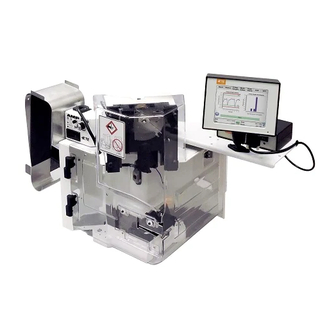
Page 4: Introduction
This manual contains descriptive information on the operation, set up, and maintenance of the Defective Crimp Cut-Off (DCC) unit installed on an AMP 3K or AMP 5K terminators. See Figure 1. The rear views are shown in Figure 3. The DCC unit and terminator (DCC terminator) are used in conjunction with a crimp quality monitor. - Page 5 409-10064 For information concerning the operation of the crimp quality monitor, 1976085-1, refer to the SL Starlite Crimp Quality Monitor Operation Instructions manual. Air feed applicators require the optional Air Feed Valve Assembly1424266-1. Refer to applicator instruction sheets for set NOTE up of applicators.
-
Page 6: Specifications
409-10064 2. DESCRIPTION The AMP 3K and AMP 5K terminators are motor driven machines. Equipped with the microprocessor controlled, pneumatically operated DCC unit, the terminator will cut off a bad termination after a crimp quality monitor (CQM) analyzes the crimp and determines it to be defective. The DCC unit also features a carrier scrap chopper which will cut the carrier strip of side feed applicators when they are equipped with a special shear that will allow a continuous strip to feed out of them. -
Page 7: Electrical Description
Figure 5 2.3. Electrical Description The AMP 3K and AMP 5K terminators electrical components consist of a motor, electrical panel, control panel, work light, switches and cables. The DCC unit electrical components consist of the operator interface panel (Figure 9), the DCC terminator control box, the electrically controlled pneumatic valves, and various switches, sensors, and cables. -
Page 8: Machine Guards
409-10064 2.4. Machine Guards (Figure 6) A combination of guards is installed to provide protection for the operator while maintaining proper visibility of the work area. The main guard swings open to the left and the hinged guard, swings open to the right to allow easy access for applicator installation and set up. -
Page 9: Receiving Inspection And Installation
409-10064 5. The crimp quality monitor analyzes the crimp and determines that it is good. 6. The grip jaws open to release the wire. 7. The operator removes the wire and terminal from the machine. 8. The carrier chop blades close to cut off the carrier strip. (If the DCC terminator controller is set to carrier chop mode.) 9. - Page 10 Move the gripper mechanism completely to the left. Manually cycle the terminator to verify tonk operation. Refer to the AMP 3K and AMP 5K customer manual 409-10047 for instructions on manually cycling the terminator. The tonk foot (the flat block bolted to the tonk rod) should hit the right side of the lower grip jaw.
- Page 11 When installing a crimp quality monitor, it is the customer's responsibility to ensure that the monitor is installed correctly NOTE and functioning properly. The AMP 3K and 5K DCC terminators require a signal from the monitor. Otherwise, the terminator will not function properly or will cut off every terminal.
-
Page 12: Considerations Affecting Placement Of A Bench Machine
409-10064 Foot Switch Inhibit Crimp Monitor Good/Bad Signal Figure 7 3.3. Considerations Affecting Placement of Bench Machines The location of the machine in relation to the operator's position is extremely important in terms of both safety and maximum efficiency. Studies have repeatedly shown that operator fatigue will be reduced, and greater efficiency achieved, if: 1. - Page 13 409-10064 Machines have provisions for being bolted to the bench. NOTE C. Operator's Chair The operator's chair should swivel, and should have independent seat height and back rest adjustments. The seat and back rest should be padded, and the back rest should be large enough to provide support both above and below the waist line.
-
Page 14: Operator Interface Panel
409-10064 4. OPERATOR INTERFACE PANEL Refer to Figure 9 and Figure 10. Crimp Inspect Step Button Chop Mode Button Select Button Error Reset Main Air “On" Main Air “Off" Error Field Chop Delay Button Button Button Button Figure 9 Rev B 14 of 26... - Page 15 409-10064 Figure 10 (Cont’d) Rev B 15 of 26...
- Page 16 409-10064 Figure 10 (End) The machine steps (see Step Mode button in Figure 10) are as follows: 1. The grip jaws close. 2. The footswitch LED on the operator interface will light, indicating that the footswitch may be pressed to cycle the terminator.
-
Page 17: Error Codes
409-10064 5. ERROR CODES When an error occurs, the yellow LED above the Error Reset button (Figure 10) will flash a code to indicate a specific error. There will be a number of flashes followed by a pause. This sequence will continue until the Error Reset button is pressed. -
Page 18: Lubrication
Empty the scrap bin and remove any debris that may have accumulated on the bench or the CSC assembly. 6.2. Lubrication In addition to the lubrication specified in the AMP 3K and AMP 5K Terminating Machine customer manual, perform the following lubrication. -
Page 19: Adjustments
409-10064 2. Turn the main terminator power on and wait for all the LEDs of the DCC terminator control panel to turn on. 3. While all the LEDs are on, press and hold the Crimp Inspect button for two seconds (after all the LEDs are turned off). -
Page 20: Tonk Adjustments
409-10064 b. Using a hex wrench adjust the gripper height adjustment screw. See Figure 12. Turning the screw clockwise will lower the grip jaw height. NOTE c. Close the guards and "power up" the DCC terminator. 4. Complete a termination cycle in step mode and observe changes. Transfer Cylinder Tonk Rod Extend Switch... - Page 21 409-10064 The tonk foot should contact the lower jaw a minimum of 3.2mm [.125 in]. NOTE B. Tonk Height Adjustment The tonk height adjustment is required to make sure that the wire is level between the terminal and gripper jaws during the crimping operation. Adjust the tonk height as follows.
-
Page 22: Transfer Left-To-Right Adjustment
409-10064 9. If the wire end is higher than the wire passing through the grip jaws, the tonk rod is too low. Adjusted as follows: a. Loosen the tonk rod T-handle (Figure 13). b. Turn the tonk rod adjustment screw counter-clockwise to raise the tonk rod. c. - Page 23 409-10064 The gripper mechanism transferring to the right isn't as critical as the mechanism transferring to the left so the extend NOTE switch location isn't as critical as the retract switch. C. Chop Cylinder Retract Switch Adjustment (Figure 14) 1. “Power up" the main air by turning the DCC terminator "on." 2.
-
Page 24: Carrier Scrap Cut (Csc) Assembly Front-To-Back Adjustment
409-10064 3. Turn "off" the main air. 4. Open the guards and look at the chop cylinder extend switch. 5. If the LED on the switch is not lit, adjust the switch. 6. Loosen the screw on the switch. 7. Slide the extend switch to the top of the cylinder. 8. -
Page 25: Fixed Carrier Chop Blade Replacement
409-10064 Top Plate Lever M4 Side Block Screws Movable Carrier Chop Blade Fixed Carrier Chop Blade M6 Air Cylinder Movable Screws Wire Blade Fixed Wire Blade Wire Blade Pin Screw Scrap Bin Clip Figure 15 9. Tighten the blade pin screw. 10. -
Page 26: Revision Summary
409-10064 10. Set the new movable carrier chop blade in the housing with the pin facing outward and the cutting surface facing down with respect to the figure. 11. Install the lever over the three pins. 12. Install the side block on the assembly. 13.
Need help?
Do you have a question about the AMP 3K and is the answer not in the manual?
Questions and answers