Advertisement
Quick Links
PROPER USE GUIDELINES
Cumulative trauma disorders can result from the prolonged use of manually powered hand tools. Hand tools are intended for occasional
use and low-volume applications. A wide selection of powered application equipment is available for extended-use production operations.
© 2022 TE Connectivity Ltd. family of companies.
All Rights Reserved.
TE Connectivity, TE connectivity (logo), and TE (logo) are trademarks. Other logos, product, and/or company names may be trademarks of their respective owners.
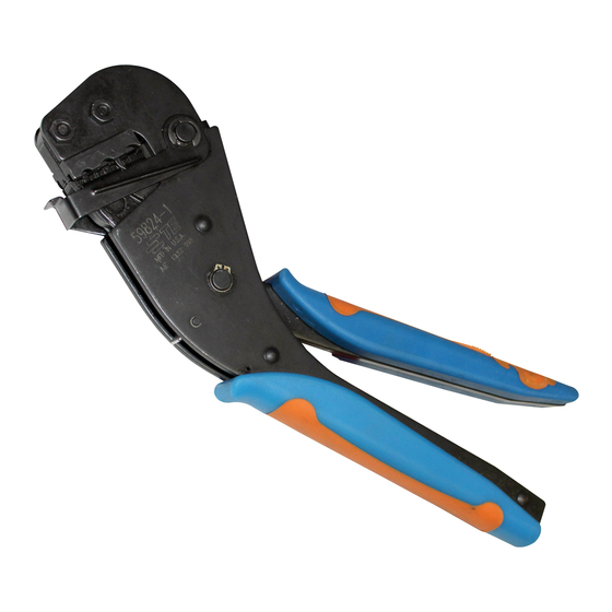
TETRA-CRIMP™ Hand Crimping Tool
PN 59824-1
Figure 1: TETRA-CRIMP Hand Crimping Tool PN 59824-1
1
Back side of tool
2
Crimping chamber (3 places)
3
Crimping chamber label
4
Ratchet handle
PRODUCT INFORMATION 1-800-522-6752
5
Ratchet pawl
6
Locator assembly
7
Crimping dies
This controlled document is subject to change.
For latest revision and Regional Customer Service,
visit our website at www.te.com.
Instruction Sheet
408-2823
Rev AB
22 JUN 2022
1 of 13
Advertisement

Summary of Contents for TE Connectivity TETRA-CRIMP 59824-1
- Page 1 1 of 13 For latest revision and Regional Customer Service, All Rights Reserved. visit our website at www.te.com. TE Connectivity, TE connectivity (logo), and TE (logo) are trademarks. Other logos, product, and/or company names may be trademarks of their respective owners.
- Page 2 Figure 2 onto stranded wire sizes 22 through 10 AWG (Table 1). For product part numbers, refer to AMP Terminals & Splices on the TE Connectivity website. NOTE Dimensions in this instruction sheet are in millimeters with [inches in brackets]. Figures are for reference only and are not drawn to scale.
- Page 3 408-2823 Table 1: Crimping specifications Crimp dot Strip length Terminal or splice Wire size Insulation diameter code* (after ±0.397 [±.016] crimping) 22-16 2.03-3.56 [.080-.140] 5.56 [.219] 16-14 2.67-4.32 [.105-.170] PIDG ring tongue terminal 12-10 3.81-6.35 [.150-.250] 8.33 [.328] 16-14 HD 3.81-6.35 [.150-.250] 22-16 2.03-3.56 [.080-.140]...
- Page 4 408-2823 3. CRIMPING 1. Select the appropriate wire size and terminal or splice for the hand tool. The wire size and insulation diameter must be within the specified range for the terminal or splice. 2. Strip the wire to the dimension provided in Table 1. Do not nick or cut the wire strands. 3.
- Page 5 408-2823 6. While holding the tool so that the back side is facing you, insert the stripped wire into the wire barrel until the wire bottoms (Figure 4). Figure 4: Inserting the wire Stripped wire Back side of tool Upper die Locator assembly Wire barrel 7.
-
Page 6: Maintenance And Inspection
408-2823 4. INSPECTING THE CRIMP Verify that the crimp dot code on the color-coded insulation indicates the crimping chamber used (see Table 1). Verify that the crimp is centered on the wire barrel (Figure 5). Make sure that the wire insulation does not enter the wire barrel (Figure 5). ... -
Page 7: Replacement And Repair
408-2823 5.1. Daily maintenance 1. Immerse the hand tool (with handles partially closed) in a reliable commercial degreasing compound to remove accumulated dirt, grease, and foreign matter. If no degreasing compound is available, the tool can be wiped clean with a soft, lint-free cloth. Do not use hard or abrasive objects that could damage the tool. - Page 8 408-2823 Gaging the crimping chamber Figure 6 shows a recommended plug gage design for the wire crimping chamber. Figure 6: Recommended plug gage design 0.51 [.020] x 45º (typical) 12.7 [.50] (typical) Width (Table 4) GO diameter (Table 4) NO-GO diameter (Table 4) Table 4: Plug gage specifications Crimping Gage element diameter...
- Page 9 408-2823 4. Try to insert the NO-GO element into the same crimping chamber. The NO-GO elemen can start entry, but must not pass completely through the crimping chamber. See Figure 7. If the crimping chambers conform to the crimping chamber inspection, the tool is considered dimensionally correct, and should be lubricated with a thin coat of any good SAE 20 motor oil.
- Page 10 408-2823 Figure 8) are listed in See Table 6 on page 11 for part numbers and descriptions. 10 of 13 Rev AB...
- Page 11 Table 6. Stock and control a complete inventory to prevent lost time when replacement of parts is necessary. Parts other than those listed should be replaced by TE Connectivity to ensure quality and reliability. Order replacement parts through your TE representative. You can also order parts by any of the following methods: ...
- Page 12 408-2823 Figure 8: Customer-replaceable parts See Table 6 on page 11 for part numbers and descriptions. 12 of 13 Rev AB...
-
Page 13: Revision Summary
408-2823 Table 6: Replacement parts Item Part number Description Quantity per tool 310581-1 Stop, terminal and wire 21018-6 Nut, 8-32 1-21116-0 Ring, retaining 7-59558-9 Pin, jaw, pivot — Frame, subassembly 354266-1 Spring, extension 7-59558-8 Pin, handle, retaining 2217549-1 Handle, plastic —...


Need help?
Do you have a question about the TETRA-CRIMP 59824-1 and is the answer not in the manual?
Questions and answers