Advertisement
Quick Links
PROPER USE GUIDELINES
Cumulative Trauma Disorders can result from the prolonged use of manually powered hand tools. Hand tools are intended for occasional use
and low volume applications. A wide selection of powered application equipment for extended-use, production operations is available.
CERTI-CRIMP*
Hand Crimping Tool
Ratchet Control
1. INTRODUCTION
This instruction sheet covers application and
maintenance procedures for Heavy Head Hand
Crimping Tools 220015-[ ]. Refer to Figure 1. The hand
tools are used to crimp a variety of coaxial connectors
with flexible cable. For applicable connector part
numbers and corresponding cable sizes, refer to
Catalog 1307191. Information pertaining to the
connectors (cable stripping dimensions and assembly
of component parts) is included in instructions
packaged with the connectors. Read all instructions
thoroughly before proceeding.
Dimensions on this sheet are in metric units
NOTE
[followed by U.S. customary units in brackets].
Figures and illustrations are for identification only
i
and are not drawn to scale.
Reasons for reissue are provided in Section 6,
REVISION SUMMARY.
2. DESCRIPTION
Each tool features integral dies that have two crimping
areas (one to crimp the center contact, and one to
crimp the ferrule), an adjustment cap that rotates the
©2012 Tyco Electronics Corporation, a TE Connectivity Ltd. company
All Rights Reserved
*Trademark
TE Connectivity, TE connectivity (logo), and TE (logo) are trademarks. Other logos, product and/or company names may be trademarks of their respective owners.
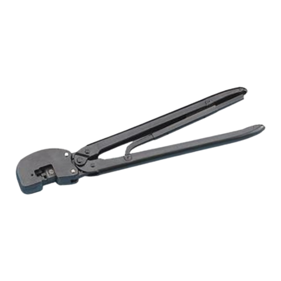
Heavy Head Hand Crimping
Tools (HHHT) 220015-[ ]
Figure 1
locator-stop (as required), and a CERTI-CRIMP hand
crimping tool ratchet control which ensures full
crimping. Once engaged, the ratchet will not release
until the tool handles have been FULLY closed.
The FRONT of the tool is marked with the part
number. The center contact enters the crimping area
from the RIGHT side of the tool. The contact/cable
assembly is inserted through the BACK of the tool for
ferrule crimping.
3. ASSEMBLY AND CRIMPING PROCEDURES
Select the appropriate cable and connector for the
tool. Slip ferrule over cable; then strip cable to the
proper length, according to instructions packaged with
the connector (plug or jack).
3.1. Crimping the Center Contact
Refer to Figure 2 and proceed as follows:
TOOLING ASSISTANCE CENTER 1-800-722-1111
PRODUCT INFORMATION 1-800-522-6752
Adjustment Cap
Integral Crimping Dies
Right Side
of Tool
1. Determine contact type (long or short) from the
dimensions provided in Figure 2. Rotate locator/
stop by turning adjustment cap to OPEN position for
long-type contacts, or CLOSED position for short-
type contacts.
This controlled document is subject to change.
For latest revision and Regional Customer Service,
visit our website at www.te.com
Instruction Sheet
408-2331
19 APR 12 Rev C
Front of Tool
Ferrule
Crimping Area
Center Contact
Crimping Area
1 of 6
Advertisement

Related Manuals for TE Connectivity 220015 Series


Summary of Contents for TE Connectivity 220015 Series
- Page 1 All Rights Reserved PRODUCT INFORMATION 1-800-522-6752 For latest revision and Regional Customer Service, *Trademark visit our website at www.te.com TE Connectivity, TE connectivity (logo), and TE (logo) are trademarks. Other logos, product and/or company names may be trademarks of their respective owners.
-
Page 2: Maintenance And Inspection Procedure
Figure 3. MAKE SURE that the ferrule assembled on the cable is on the upper crimping die, and that TE Connectivity recommends that a maintenance and the shoulder on the connector rests against the die, inspection program be performed periodically to as shown. -
Page 3: Replacement And Repair
408-2331 C. Gaging the Crimping Chambers 1. The care, amount of use, and handling of the hand tool. This inspection requires the use of a plug gage 2. The presence of abnormal amounts of dust and conforming to the dimensions provided in Figures 4 dirt. - Page 4 408-2331 Figure 4 Rev C 4 of 6...
- Page 5 408-2331 Figure 5 4. The NO-GO gage may enter partially, but must 1. Position the connector and wire between the NOT pass completely through the crimp die closure. crimping jaws, as described in Section 3, ASSEMBLY AND CRIMPING PROCEDURES. D. CERTI-CRIMP Hand Crimping Tool Ratchet Control Inspection 2.
-
Page 6: Revision Summary
408-2331 [.001 in.], the ratchet is out of adjustment and must CUSTOMER SERVICE (038-035) be repaired. See Section 5, REPLACEMENT AND TYCO ELECTRONICS CORPORATION REPAIR. PO BOX 3608 HARRISBURG PA 17105-3608 5. REPLACEMENT AND REPAIR For tool repair service, please contact a TE Replacement parts are listed in Figure 6.
Need help?
Do you have a question about the 220015 Series and is the answer not in the manual?
Questions and answers