Table of Contents
Advertisement
Quick Links
See also:
Manual
D-Show Guide
2001 Junipero Serra Boulevard
Daly City, CA 94014-3886 USA
Version 1.1
Digidesign
tel: 650·731·6300
fax: 650·731·6399
Technical Support (USA)
tel: 650·731·6100
fax: 650·731·6384
Product Information (USA)
tel: 650·731·6102
tel: 800·333·2137
International Offices
Visit the Digidesign Web site
for contact information
Web Site
www.digidesign.com
Advertisement
Table of Contents

Subscribe to Our Youtube Channel
Related Manuals for DigiDesign D-show


Summary of Contents for DigiDesign D-show
- Page 1 2001 Junipero Serra Boulevard Daly City, CA 94014-3886 USA tel: 650·731·6300 fax: 650·731·6399 Technical Support (USA) tel: 650·731·6100 fax: 650·731·6384 Product Information (USA) tel: 650·731·6102 tel: 800·333·2137 International Offices Visit the Digidesign Web site for contact information Web Site www.digidesign.com...
- Page 2 Copyright Important Safety Instructions This guide is copyrighted ©2005 by Digidesign, a division of Avid Technology, Inc. 1) Read these instructions. (hereafter “Digidesign”), with all rights reserved. Under copyright laws, this guide may not be duplicated in whole or in part without the written consent of 2) Keep these instructions.
-
Page 3: Table Of Contents
D-Show Main Unit and Sidecar Top Panels ........ - Page 4 Other D-Show Options........
- Page 5 Chapter 9. Groups ................71 Configuring Group Busses .
- Page 6 Assigning Hardware Inserts from the Patchbay ............135 D-Show Guide...
- Page 7 Snapshot Controls on the D-Show Control Surface ........
- Page 8 Installing the D-Show Standalone Software ........
- Page 9 Chapter 30. Stage Rack Reference ............. . . 217 Stage Rack Front Panel .
- Page 10 D-Show Guide...
-
Page 11: Part I Overview And Installation
Part I: Overview and Installation... -
Page 13: Chapter 1. D-Show System Introduction
D-Show Expansion Options coders The following options may be added to a D-Show system. For • Built-In High-Pass Filter, Dynamics and EQ processors on details on D-Show expansion and customization options, visit each Input channel strip the Digidesign Web site (www.digidesign.com). -
Page 14: D-Show System Components
Software CDs HDx Record/Playback Option This option lets you record or • System Restore CD play back up to 128 channels of audio directly from D-Show • Standalone Software Installer CD with a Pro Tools HD system. Additional Required Components... -
Page 15: Operational Requirements
For Snake cable specifications and requirements, visit Digidesign’s Web site (www.digide- Cleaning and Maintenance sign.com). If you need to clean the D-Show top surface, use a dry cloth. Audio Connections Do not apply any cleaning solutions, spray cleaners, or abra- sives to the surface. - Page 16 D-Show Guide...
-
Page 17: Chapter 2. Configuring And Connecting D-Show
Chapter 2: Configuring and Connecting D-Show The D-Show Main Unit and Sidecar can be placed in any or- Expanded System Layout der, and the input channel strip order configured accordingly. On expanded D-Show systems, by default, input channel You can then bank input channels across the available input strips 1–16 appear on the leftmost Sidecar and progress to the... - Page 18 • Set the ID to 2 on the unit you want to have the second set of input faders. For example, on a standard D-Show system (one Sidecar and one Main Unit) where the Side- car is at the left of the Main Unit, the Main Unit should be set to Bus ID 2.
-
Page 19: Connecting D-Show Components
SERIAL NUMBER System Drive FOH Link Reset Power To Control Surface FOH Rack (Front) FOH Rack (Back) Digital Snake Cables Stage Rack (Front) STAGE Primary Snake Redundant Snake Figure 1. D-Show system component connections Chapter 2: Configuring and Connecting D-Show 9... - Page 20 Connecting the D-Show Main Unit and Sidecars The D-Show Main Unit and Sidecars are connected with Console Link cables (one 15-foot cable is provided with each Sidecar), which are 110-ohm AES/EBU digital cables. The maximum length permissible for each Console Link cable is 25 feet (7.6 meters).
- Page 21 If a second Stage Rack is used, an additional Snake Card must be installed in the FOH Rack. Follow the above in- structions to connect the second Stage Rack to its corresponding Snake card. Chapter 2: Configuring and Connecting D-Show 11...
-
Page 22: Connecting A Second Stage Rack
Connecting a Second Stage Rack Before connecting a second stage rack to a D-Show system, a second Snake card (purchased separately) must first be installed in the FOH Rack. To connect a second Stage Rack: Install a second Snake card in the FOH Rack. See the documentation that came with the Snake card. -
Page 23: Power Connections
Connect analog line-level output destinations (such as Stage Rack Input, make sure phantom power is turned off power amplifiers, crossovers, or speakers) to any of the output for that input. connectors on any SRO Card. Chapter 2: Configuring and Connecting D-Show 13... - Page 24 48 kHz. Monitor Outputs (Balanced 1/4-inch TRS Connectors) Connect a monitor amplifier or powered monitors to the Monitor Output connectors. The Monitor Outputs, and the Headphone Output on front of the Main Unit, are fed by the Solo/Monitor bus D-Show Guide...
-
Page 25: Control Surface Connections
Connect a compatible MIDI device to the MIDI In and MIDI VGA display connector on back panel of the Main Unit Out ports. The D-Show Snapshot feature receives and sends MIDI commands, and generates and responds to MIDI Time USB Keyboard Code. -
Page 26: Powering Up The System
Setting the System Clock Detail of Devices page showing connection to second Stage Rack When you first work with a D-Show system, make sure the sys- The second Stage Rack must be enabled for the Devices tab tem clock time, date and time zone are set appropriately. The... -
Page 27: Part Ii System Description
Part II: System Description... -
Page 29: Chapter 3. D-Show Control Surface Overview
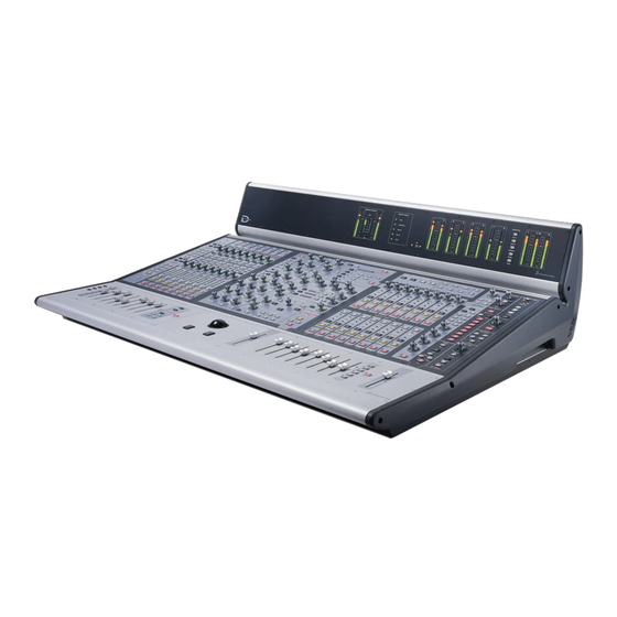
Chapter 3: D-Show Control Surface Overview D-Show Main Unit and Sidecar Top Panels The following figure identifies the main sections of the D-Show control surface: Sidecar Main Unit Input Channels Input Section Assignable Channel Section Output Section KICK KICK KICK... -
Page 30: Input Channels And Faders
If the LED is off, that Input meter channel will be silenced when soloing another channel. Stereo LED Select switch Solo switch Source Name Display switch Mute switch Make Stereo switch Global Modifier switches Fader Banks Faders Input strip and fader controls D-Show Guide... - Page 31 Bus Assignment Indicators Rotary and Switch Functionality D-Show rotary encoders are dual-function controls that pro- These green LEDs indicate Group bus assignments, and can vide rotary and switch functions. In addition to adjusting pa- also show VCA or Mute Group membership for each channel.
- Page 32 When D-Show is in Variable Groups mode, the switches for Width (Stereo Channels Only) Assigns the encoders to control Aux 1–2 through Aux 7–8 can be used to select Variable Group the ganged pan positions of Left channel and Right channel at sends, and use the Encoder 1 to control the Variable Group the same time, but in opposite directions.
- Page 33 2 seconds or more and released. There are three meters within this section in the channel strip. D-Show Input (and Output) meters display nominal level. Source Switch Input Meter...
-
Page 34: Assignable Channel Section (Acs)
ACS Auxes Channel Config Console Config/Show mode target. The faders on D-Show can be moved even when they do not sense a touch. This allows use of the faders while wearing Assign Insert Processing gloves. -
Page 35: Assignable Output Encoders
Groups Assigns the Output Encoders section to Groups. The Direct Output section provides level and in/out control for the channel direct output. When D-Show is in Variable Groups mode, this switch assigns the Output Encoders section to control Variable Groups. Solo and Mute Group Pan Assigns the Output Encoders to (stereo) Group pan. -
Page 36: Assignable Output Faders
Output has a Dynamics plug-in Groups Assigns the Output Faders to control Group levels. assigned and in-circuit When D-Show is in Variable Groups mode, this switch assigns Yellow Output has one or more Dynamics the Output Faders to control Variable Groups. -
Page 37: Master And Global Controls
F1 Serves as a clutch to be able to trim one side of a stereo linked Aux without affecting the other side. F2 When D-Show is in Variable Groups mode, the F2 switch is used to toggle display of Variable Group controls in the Input Encoder rows and the ACS. -
Page 38: Meter Bridge
When all components are communicating properly, the Sta- tus LEDs light green. If any Status LEDs are flashing, or red, it indicates possible problems with that component of the sys- tem. See Chapter 27, “Troubleshooting.” D-Show Guide... -
Page 39: Chapter 4. Basic Commands And Modes
Control Overview With the Trackball, place the cursor over a screen item to dis- Most D-Show features and controls that are used during a per- play a brief explanation of that item in the banner display. formance are available from both the control surface and on-screen. -
Page 40: Config Mode And Show Mode
For details on how to se- lect one or more channels, see “Selecting and Targeting Chan- Show mode is the main operating mode for D-Show. All mix- nels” on page 36. ing and routing features are available, based on your settings for Config mode options. -
Page 41: Software Screen Pages And Tabs
To reset Threshold on-screen: Software Screen Pages and Tabs Select an input or output channel on-screen. Do one of the following: Viewing Pages • Right-click the Threshold encoder on-screen and choose Reset. To view a page, do any of the following: –... - Page 42 Snapshots Inputs page Store and recall snapshots. See Chapter 7, “Inputs and Input Routing.” Outputs Select, name, configure, and adjust parameters for outputs. Snapshots page See Chapter 21, “Snapshots.” Outputs page See Chapter 8, “Outputs and Output Routing.” D-Show Guide...
- Page 43 Patchbay Options Route and name physical inputs and outputs to control sur- Configure control surface, Main busses (L–R+M, L–C–R), cus- face channels. tomize/optimize targeting, metering, modes, devices, install plug-ins, and set other system options. Patchbay (Inputs tab) Options page (System Config tab) See Chapter 12, “Patchbay.”...
- Page 44 D-Show Guide...
-
Page 45: Chapter 5. Navigating And Selecting Channels
Many D-Show configurations utilize more physical inputs To return the Main Unit input faders to Input Channel banking, do than input faders. For example, a standard D-Show system one of the following: provides up to 48 discrete hardware inputs and 24 input fad- Press a lit FX Returns switch (1–8 or 9–16). -
Page 46: Selecting And Targeting Channels
Selecting and Targeting Channels to the Assignable Output Encoders: Press Encoder Assign switch, located to the right of the Out- Each D-Show channel strip has a channel Select switch. The put Encoder row. Select switch targets that channel for routing or processing as- signment. - Page 47 Multi-Assign switch and the banner display at the lower left of Multi-Assign the screen indicate that Multi-Assign mode is enabled. There are two types of Multi-Assign switches on D-Show, as Press the Select switches on the channels you want to assign follows: to the Aux, Group (or Variable Group) or VCA.
-
Page 48: Targeting Plug-In Inserts
Press the Tab key to cycle through and select any other channels beginning with that letter (such as Snare Top, Snare Bottom, or Strings). Channel Numbers and Names D-Show channel numbers are “absolute” channel numbers. Fader in Renaming changes the displayed name associated with each selected channel channel, but the absolute channel number remains fixed. - Page 49 To adjust a value on-screen by dragging: channels. D-Show must be in Config mode to change the ste- Click in the text box to select the value. reo status of a channel.
- Page 50 To reset an on-screen fader or encoder to its default value, do one of the following: Right-click the control and choose Reset. – or – Alt-click the control. Reset Strip To reset an entire channel strip to its default settings: Right-click the on-screen channel fader and choose Reset Strip. D-Show Guide...
-
Page 51: Chapter 6. Options
Click the Options tab on-screen. (since changes to these settings can interrupt audio). The System Configuration and Devices screens provide the System Configuration settings on a standard D-Show system primary tools by which you configure D-Show mixing, rout- Input Channels FX Returns Graphic EQs ing, and processing options. - Page 52 Mix Engines Add Mix Engine cards, disable the second Stage Rack, or re- On a complete D-Show system, the Mix Engine setting is de- duce the number of Channels, FX Returns, or Graphic EQs. termined by the number of DSP Engine Cards detected and cannot be changed.
- Page 53 Stage Rack inputs with fixed HDx card outputs. On systems with 2 Stage Racks and 2 HDx cards, you can replace the in- Changing the Main Bus mode will restart the D-Show soft- puts from each Stage Rack independently. ware and may interrupt audio.
-
Page 54: Devices
Devices tab of the Options page Auxiliaries & Variable Groups On the D-Show system, you can use this page to update the These options let you designate bus link status, pick off system when adding expansion options, or to view compo- source, and stereo pan behavior. - Page 55 To change the Aux bus or Variable Group bus configuration: Stereo Group Panning Operation Put D-Show in Config mode. (Not Available in Variable Groups Mode) Go to the Options page and click the Busses tab. The Stereo Group Panning Operation options provide differ- ent levels of flexibility for how channels can be routed to Click Edit.
- Page 56 MIDI channel The following settings are available in the Snapshots page. MIDI Snapshot Output Safe Safes (shuts off) D-Show MIDI out- put of when snapshots are recalled. This does not affect send- See Chapter 21, “Snapshots.”...
- Page 57 Options in this section set the mechanism by which channels are targeted on the ACS. Talkback To customize D-Show control surface and screen interaction: Talkback Level Lets you activate Talkback and set Talkback in- Go to the Options page and click the Interaction tab.
- Page 58 The Plug-Ins tab of the Options page is used to install plug-ins • Toggle Mute Group 8 on the D-Show system. The Plug-Ins tab is available on com- • Toggle Encoder 1 Flip to Faders plete D-Show systems only. It is not available in the D-Show •...
-
Page 59: Part Iii Signal Routing
Part III: Signal Routing... -
Page 61: Chapter 7. Inputs And Input Routing
Sidecars in the system. Depending on the number of Mix Engines installed in the sys- tem, you can set D-Show to have either 8 or 16 available FX Returns. FX Returns are always stereo channels. - Page 62 Combining Input Channels (Make Stereo) To split stereo channels and make them mono: Put D-Show into Config mode. Pairs of mono Input Channels can be combined to make ste- reo channels, whose left and right sides are then controlled by Press the Make Stereo switch so that it flashes.
-
Page 63: Assigning Inputs To Channels
Assigning Inputs from Bus-Fed Plug-Ins Assigning Inputs to Channels Inputs from bus-fed plug-ins are routed to Input Channels Available input sources for Input Channels or FX Returns in- and FX Returns from the Plug-In Rack. For more information clude: on routing signals to plug-ins, see “Using Plug-Ins as a Bus •... -
Page 64: Routing Inputs To Direct Outputs
Routing Channels to Auxes top row of rotary encoders. D-Show can be configured to have 8 or 16 available Aux bus- Turn the assigned rotary encoder to set the Compres- ses as part of the overall Aux/Group bus configuration. Aux sor/Limiter threshold value. -
Page 65: Using Inserts On Channels
Input Channel or FX Return. Using Hardware Inserts on Channels Using Plug-In Inserts on Channels D-Show lets you insert external processors in the signal chain of Input Channels and FX Returns. Plug-Ins are arranged in virtual racks, which allow signals to... -
Page 66: Using Input Direct
FX Return: digital inputs). Gain change is indicated by the encoder ring Press the Insert In switch on the channel. The switch lights LEDs, and gain value is shown in the channel display. when the insert is in-circuit. D-Show Guide... - Page 67 Setting Input Gain To adjust input gain using the Gain Guess feature: Press and hold the assigned rotary encoder while the chan- Gain can be controlled from individual channel strips or from nel is receiving input signal. The LED flashes to indicate level the ACS section.
- Page 68 Press the 20 dB Pad switch in the ACS Input section. The switch lights when the pad is applied to the Stage Rack input. The Gain Guess feature may turn the Pad on or off to ac- commodate incoming signal level D-Show Guide...
- Page 69 Input Polarity (Phase) Invert Channel Faders Channel Faders provide channel level control from – ∞ (–INF) The polarity of any Input Channel or FX Return signal can be inverted. With stereo channels, only the left channel is in- to +12 dB. verted.
- Page 70 D-Show Guide...
-
Page 71: Chapter 8. Outputs And Output Routing
Chapter 8: Outputs and Output Routing Variable Groups Configuring Outputs When D-Show is in Variable Groups mode , the 8 Group busses operate in much the same way as Aux busses. This bus config- Types of Outputs uration mode lets you send independently controllable sig- nals to all 24 busses in the system. - Page 72 Setting the Main bus configuration able Groups): Select the configuration for the Main Busses. • Group Bus Output levels Click Apply. D-Show restarts with the new Main bus config- • Group Bus Plug-In routing uration. • Group Bus Graphic EQ assignments •...
-
Page 73: Routing Busses To Hardware Outputs
The Patchbay Outputs page shows the name of the bus or Naming Channels mixer and its destination. The destination is also displayed be- Output channel names can be changed from the Outputs page low the channel name in the Outputs page and Patchbay Out- or from the Patchbay. -
Page 74: Using Inserts On Output Busses
Using Hardware Inserts on Output Busses Yellow Group output is routed to the Mains L–R bus. D-Show lets you insert external processors in the signal chain Green Group output is routed to the Mains C/M bus. of Output busses. Signals from these sources are routed to and from analog or digital I/O connectors on the FOH Rack. -
Page 75: Inserting The Built-In Graphic Eq On Output Busses
The name of the hardware insert destination appears in the Inserting the Built-In Graphic EQ on on-screen Hardware Insert button. Output Busses If the output bus is assigned to the Assignable Output Encod- A built-in 31-band Graphic EQ can be inserted on any of the ers or Assignable Output Faders, the corresponding Insert LED following Output bus types: Mains, Groups (or Variable lights to indicate the presence of an insert. -
Page 76: Adjusting Output Controls
Aux bus fader. • Hold the Start (Win) key on the keyboard and move one For more information on Solo bus operation, see Chapter 14, linked Aux bus fader on-screen. “Solo and Monitor Busses.” D-Show Guide... -
Page 77: Adjusting Main Bus Controls
The Main bus output levels are controlled from the single Press the ACS Delay rotary encoder to apply the delay to the Mains Fader located on the far right of the D-Show Main Unit. bus. Adjust the delay value by turning the Delay rotary encoder. -
Page 78: Monitoring The Main Mix
Assigning a Direct Output in the Patchbay Directs page To configure the Direct Output pickoff point for Inputs: Go to the Options page and click the Pickoffs tab. Under “Input Strip Fader Pickoff Point,” click Pre-Fader or Post-Fader. D-Show Guide... -
Page 79: Matrix Mixers
Assigning and Using VCAs you want to solo so that the Solo switch is lit. D-Show VCA controls emulate the operation of VCA (Voltage To mute the members of a VCA: Controlled Amplifier) groups. Up to eight VCA faders are... - Page 80 D-Show Guide...
-
Page 81: Chapter 9. Groups
Chapter 9: Groups The D-Show Output section has 8 available Group busses. Press the Select switches on the other channels you want to Groups busses can fed by Input Channels and FX Returns. route to a Group bus. Group outputs can be assigned to the Main Output busses and In the ACS Bus Assigns section, press any of the Group to any hardware outputs on the system. -
Page 82: Group Bus Signal Flow Options
Stereo Input Signals Contributing stereo signals are panned across the linked odd/even Group bus pair. Balance and width information from each stereo input channel determines its contribution to the odd and even sides of the bus pair. D-Show Guide... -
Page 83: Adjusting Group Bus Output Controls
Press the Group Pan switch in the Output Encoder assign- ment section to assign control of Group pan to the Assignable You can insert D-Show software plug-ins or hardware inserts Output Encoders. on Group bus outputs. For more information, see “Using In- Turn a rotary encoder to adjust the pan for the correspond- serts on Output Busses”... -
Page 84: Simple And Expert Operational Modes
To switch between Simple mode and Expert mode: Expert Mode Put D-Show into Config mode. In Expert Mode, any of the 8 stereo Group busses can be set to Go to the Options page and click the Busses tab. -
Page 85: Chapter 10. Auxes And Variable Groups
Chapter 10: Auxes and Variable Groups The D-Show Output section has up to 16 available Aux busses, Displaying Variable Group Controls and when set to Variable Groups mode, the 8 Group busses are When D-Show is in Variable Group mode, Variable Group replaced by Variable Group busses. - Page 86 Aux bus pairs and Variable Group bus pairs are linked on a global basis, and appear as linked on all channels. To link Aux bus paris or Variable Group bus pairs: Put D-Show into Config mode. Go to the Options page and click the Busses tab. Bus Pair Links Linking bus pairs in the Options >...
- Page 87 Send Pickoff Points Go to the Inputs page and target the channel with the pick- D-Show lets you set the pickoff point on Input Channels or FX off point you want to activate by clicking its on-screen chan- Returns channels for Aux Sends and Variable Group Sends.
-
Page 88: Assigning Inputs To Aux Busses And Variable Group Busses
Target the Aux bus or Variable Group bus output channel you want to change by selecting its on-screen channel strip. Variable Group channels are labeled “Groups” in the channel display. Click the pop-up menu at the bottom of the Members list and choose Reset Mix. D-Show Guide... - Page 89 Copying Assignments Between Aux Busses Copying Mains Assignments to Aux Busses and Variable Group Busses and Variable Group Busses You can copy the current input assignments from one Aux You can copy the current Main bus assignments to Aux busses bus or Variable Group bus to another bus of either type.
-
Page 90: Aux Bus And Variable Group Bus Signal Flow Options
Pan control. • When the Follows Channels Pan option is on, the bal- ance from each stereo input channel determines its con- tribution to the odd and even sides of the bus pair. D-Show Guide... -
Page 91: Adjusting Aux Bus And Variable Group Bus Output Controls
Controlling Aux Send and Variable Group Send Pan Adjusting Aux Bus and Variable Group When Aux busses or Variable Group busses are linked, input Bus Output Controls signals are panned across the bus pair. Panning can be con- trolled from the Input section or from the ACS Aux Sends sec- Aux Bus and Variable Group Bus Output tion. -
Page 92: Routing Aux Busses And Variable Group Busses To Direct Outputs
Using Inserts on Aux Bus and Variable Group Bus Outputs You can insert D-Show software plug-ins or hardware inserts on Aux bus or Variable Group bus outputs. For more informa- tion, see “Using Inserts on Output Busses” on page 64. -
Page 93: Chapter 11. Matrix Mixers And Pq Mixers
Chapter 11: Matrix Mixers and PQ Mixers The D-Show Outputs section offers 8 Matrix mixers and 8 PQ mixers for setting up alternate mixes, fill and delay tower feeds, and cue or monitor mixes. Inputs Matrix mixers and PQ mixers can be configured independently to have different input sources. Matrix and PQ input sources can be controlled from the Assignable Output Encoders or on-screen. -
Page 94: Personal Q Mixers
8 Groups appear on the Matrix or PQ mixer. Under Matrix Sources, select the input source for channels 1–8 of the Matrix mixer and for channels 1–8 of the PQ mixer. Choices include Groups (pre- or post-fader) and Auxes (pre- or post-fader). D-Show Guide... -
Page 95: Adjusting Matrix Mixer And Pq Mixer Input Controls
Select the input source for the Mains channels of the Matrix Adjusting Matrix Mixer and PQ Mixer mixer and the PQ mixer. Choices include pre-fader or Input Controls post-fader. The Group, Aux and Main configurations are applied globally Matrix and PQ Mixer Input Levels to all 8 Matrix mixers or PQ mixers. -
Page 96: Adjusting Matrix Mixer And Pq Mixer Output Controls
Click the pop-up menu at the bottom of the mixer area, choose Replace With Mix From, then choose the mixer whose settings you want to copy to the current mixer. D-Show Guide... -
Page 97: Using Inserts On Matrix And Pq Mixer Outputs
When an optional Personal Q remote control system is con- Matrix mixers. nected to D-Show, it can be used to adjust the controls in the Personal Q mixers from a remote location. To apply delay to a Matrix mixer output:... - Page 98 D-Show Guide...
-
Page 99: Chapter 12. Patchbay
Patchbay screen (whether an input, output, or bus). Channel Type Tabs Click these tabs to select specific types of D-Show Channels, as available for the currently selected I/O. The following table shows the available Channel Types for the current I/O. - Page 100 Patchbay” on page 92. The Patchbay indicates I/O that is offline or unavailable by By default, inputs are routed in a 1-to-1 pattern to D-Show in- graying out the columns beneath that device. put channels resulting in Stage Rack inputs 1–24 appearing on D-Show Input Channels 1–24.
-
Page 101: Navigating The Patchbay
When you type a To view full names of a patch source and destination: number, D-Show navigates to absolute channel numbers regardless of the channel name. Place the cursor over a Channel Name. If the channel is al- ready routed, its source and destination assignment appear di- rectly above the Patching Grid, as shown below. -
Page 102: Routing Channels In The Patchbay
Press the Left or Right Arrow keys on the keyboard. hardware I/O source. For example, to route Stage Rack analog input 4 to D-Show Input Channel 4, click in row 4, column 4 To scroll the Patching Grid, do one of the following: as shown below. - Page 103 68. Multiple input Direct Output Pickoff Points assignments D-Show lets you specify the pickoff point from which Direct Outputs are sourced. To specify a Direct Out pickoff point: Navigate the Patchbay to the Outputs > Directs screen.
- Page 104 Inserts and Routing in the Patchbay Hardware inserts are available on all D-Show channels to in- corporate external hardware processing. D-Show inserts can only be routed to and from the FOH Rack. Inserts patching uses the same techniques as other Patchbay routing.
-
Page 105: Chapter 13. Metering
Chapter 13: Metering D-Show provides signal metering on the control surface chan- Channel Input Level meter scale nels and meter bridge, and on-screen. Level Color –6 dB Green Channel Meters –9 dB Green –12 dB Green All control surface channel meters have on-screen equivalents... -
Page 106: Acs Section Dynamics Meters
LED flashes to indicate momentary clips, and lights solid for 10 (left) 60 dB sustained clipping. To locate the clipped channel: Press the Channel Bank switches until the Channel Input Level meters show clipping. For more information on clip indication, see “Metering Op- tions” on page 99. D-Show Guide... -
Page 107: Meter Bridge
Selected Channel and Solo Bus Meters Meter Bridge The Selected Channel meters in the meter bridge include two The D-Show meter bridge includes meters for the selected 20-segment bi-color level meters and two 10-segment dynam- channel, the Output section, and the Main Outputs. - Page 108 LEDs mirrors that on the channel itself. When the Selected Channel meters in the meter bridge are showing Solo bus levels, the meter LEDs turn red to indicate clipping on the Solo bus. D-Show Guide...
-
Page 109: Metering Options
Clipping can occur at several points throughout the signal chain. A clip at any one of these points is indicated on the meter. For more information on the location of D-Show clip detect points, refer to Chapter 26, “Signal Flow Diagrams.”... - Page 110 D-Show Guide...
-
Page 111: Chapter 14. Solo And Monitor Busses
Solo Bus Modes SIP Solo mode applies to Input Channels and FX Returns only. D-Show offers three modes for soloing channels in the system: Solo In Place sends the signal from the soloed channel to the Pre-Fader Listen (PFL), After-Fader Listen (AFL) and Solo In Main busses. -
Page 112: Solo Operation Options
To latch solo on a channel: Press and release the solo switch. Press the switch a second time to unsolo the channel. D-Show Guide... -
Page 113: Solo Bus Operation
Auto Cancel and Input Priority Soloing Single Channels The Auto Cancel option determines whether Solo switches To solo a single channel, do one of the following: cancel other soloed channels or are additive (latching). The Press the channel’s solo switch so it is lit. The solo switch Input Priority option determines whether soloed inputs re- latches on a momentary press. -
Page 114: Solo Safing Channels
For more information, see “Metering on the Solo Bus” on output (on the FOH Rack) and headphone output (on the page 98. front of the D-Show Main Unit). Monitor Bus Switching Solo Safing Channels The following signals can feed the Monitor bus, listed below in order of priority: Key Listen, Solo bus, 2-Track return, and Only Input Channels and FX Returns can be made solo safe. -
Page 115: Talkback, 2-Track And Oscillator Controls
Using Talkback Solo bus monitoring levels are controlled by the Level Trim The Talkback input on the top panel of the D-Show Main Unit knob in the Solo/PFL section. The trim amount is adjustable can accept signal from any dynamic microphone. - Page 116 To route Talkback microphone input to any D-Show output bus: Activating Talkback Input and Setting Level Press the Talkback switch in the Talkback/Osc section of the To activate and set the level for Talkback input: Main Unit so that it is lit.
- Page 117 Rack can accept input from any compatible dynamic or con- on the rear panel of the FOH Rack. denser microphone. Routing 2-Track Input Com Mic Input To route the 2-Track inputs to any D-Show Input Channel or FX Com Mic Phantom Return: Com Mic Gain Power Go to the Patchbay and click the Inputs tab.
- Page 118 You can route any output bus or Direct Output to the 2-Track ment. output on the FOH rack. To route any D-Show Output bus to the 2-Track outputs: Go to the Patchbay and click the Outputs tab. To the left of the channel grid, click the tab for an Output bus (Auxes, Groups, PQs, Matrixes, or Mains).
- Page 119 Press the flashing Route to Selected switch to confirm the as- Routing Oscillator Output signment, or press the Cancel switch to cancel the assign- The output of the D-Show internal oscillator can be routed to ment. any of the output busses.
- Page 120 D-Show Guide...
-
Page 121: Chapter 15. Muting And Mute Groups
Chapter 15: Muting and Mute Groups Muting Output Busses Muting Mute operation is post-fader on all types of Output busses. Channels can be muted in three ways: explicitly (lit solid), with the channel mute switch; implicitly (flashing), as a result To control the mute status of an output bus: of another channel being soloed, and as a member of a Mute Press one of the following switches in the Output Fader or... -
Page 122: Mute Groups
Mute Groups Press the Select switch for each channel you want to assign D-Show lets you assign channels to any of 8 available Mute or remove from the Mute Group. The Select switches on the Groups. Mute Groups let you mute and unmute multiple selected channels flash. - Page 123 Viewing Members of Mute Groups Disabling Mute Groups You can view Mute Group members in Input Channels and You can temporarily disable all Mute Group functions. When FX Returns Mute Groups are disabled, all channels implicitly muted as a result of Mute Group activation are unmuted. To view the members of Mute Groups in the Inputs section: Channels can still be explicitly muted when Mute Groups are Press the Show Members switch in the Mute Groups section.
- Page 124 D-Show Guide...
-
Page 125: Part Iv Processing
Part IV: Processing... -
Page 127: Chapter 16. Dynamics
ACS Ratio encoder, the on-screen Comp/Lim D-Show busses. Dynamics plug-ins can be adjusted using the Ratio encoder, or by dragging the Ratio handle in the dedicated Dynamics controls in the ACS, or from the on-screen Dynamics Graph display. -
Page 128: Built-In Expander/Gate
Input Channels. 10-segment gain reduction meters are provided in the ACS for higher resolution metering of the Expander/Gate on the cur- rently selected channel. See Chapter 13, “Metering.” D-Show Guide... -
Page 129: Channel Modes Affecting Dynamics
Expander/Gate Defaults and Ranges Adjusting Dynamics The following table lists the default values for the Ex- D-Show provides Dynamics controls in input channel strips, pander/Gate: the ACS, and on-screen. Exp/Gate Defaults (defaults to Gate mode) Parameter Default Minimum Maximum Input Fader Strip Dynamics Controls... - Page 130 Its six dual-purpose ro- Exp/Gate parameters (including their side-chain settings). The tary/switch encoders, three In/Out switches, three Select D-Show screen also provides the Dynamics Graph display. switches, and dedicated high-resolution gain reduction The Dynamics Graph displays a composite response of the...
-
Page 131: Dynamics Settings And Presets
Control Surface Encoders for Rotary and Switch Functions Copying and Pasting Dynamics Settings D-Show encoders are dual-purpose controls that provide ro- tary and switch control of parameters, as follows: To copy and paste dynamics settings: Rotating a dynamics encoder adjusts its assigned parameter Right-click anywhere in the Comp/Lim or Exp/Gate areas of (such as Threshold or Ratio). -
Page 132: Side-Chain Keys And Filters
The built-in Compressor/Limiter and Expander/Gate support Presets for Built-In Dynamics side-chain triggering. D-Show lets you store and load dynamics settings as presets Key In/Out for built-in and plug-in dynamics processors. Presets can be accessed from the control surface or on-screen. - Page 133 Key Sources Key Listen The Compressor/Limiter can be self-keyed. The Ex- The Key Listen switch toggles the key onto the Main Solo bus, pander/Gate can be self-keyed or use any available input, out- replacing the signal there. This happens regardless of whether put, bus, or hardware channel as the key signal with a select- the key is the channel signal or the external key, or whether it able source pickoff point.
- Page 134 FX Return top-of-channel pickoffs, or channel insert returns. Side-chain level may vary dramatically depending on where the Key signal is sourced. The top of channel pickoff can be as much as 18 dB louder than other pickoff points and sources. D-Show Guide...
-
Page 135: Chapter 17. Eq
D-Show provides the following EQ features: Hardware Inserts • A built-in EQ is available on each Input Channel and FX D-Show lets you insert a hardware EQ processor and control Return. its routing and in/out state. Routing must be performed •... -
Page 136: Channel Modes Affecting Eq
Gain knob for each band serves as the in/out con- trol by pushing the encoder. The indicator LED lights to indi- cate band In. On-screen, a dedicated In/Out switch is located just below each Gain knob. D-Show Guide... -
Page 137: Adjusting Eq
ACS EQ Controls Adjusting EQ The EQ controls in the ACS provide a unified, consistent set of D-Show provides EQ controls in input fader strips, the ACS, controls for both built-in and plug-in EQ processing for the and on-screen. targeted channel. One dual-purpose rotary/switch encoder controls the HPF. - Page 138 Press the EQ In switch to enable built-in EQ on that chan- nel. (The EQ In switch is provided in the ACS as well as in each The D-Show software screen also provides the EQ Graph dis- input fader strip.) play to adjust frequency and gain simultaneously.
-
Page 139: Graphic Eq For Outputs
Output Configuring Graphic EQs To configure the number of Graphic EQs: Bands Put D-Show into Config mode. Go to the Options page and click the System Config tab. Click the Edit button on-screen. 31-band graphic EQ Chapter 17: EQ 129... -
Page 140: Plug-In Mapping Of Eq Controls
Plug-In Mapping of EQ Controls The Input Faders of the Main Unit provide control of Graphic D-Show compatible EQ plug-ins can map their gain, fre- EQ in/out, and targeting of EQ bands. You can also use quency, and Q/bandwidth controls to corresponding encod- on-screen controls to adjust graphic EQ parameters. - Page 141 Presets for Built-In and Graphic EQ • To load the currently selected preset, press Enter or click D-Show lets you store and load EQ settings to disk as Preset the Close box in the Presets window title bar. files. Presets can be used with built-in and plug-in EQ proces- •...
- Page 142 630 Hz Bank 3 800 Hz 1000 Hz 1.25 kHz 1.6 kHz 2 kHz 2.5 kHz 3.15 kHz 4 kHz Bank 4 5 kHz 6.3 kHz 8 kHz 10 kHz 12.5 kHz 16 kHz 20 kHz Output Level D-Show Guide...
-
Page 143: Chapter 18. Hardware Inserts
Chapter 18: Hardware Inserts D-Show lets you route signal to and from external devices as hardware inserts. Hardware inserts may be used on Input Channels, FX Returns, Groups, Auxes, Matrixes, Personal Qs, and the Main busses. Up to 16 analog and 8 digital hardware inserts may be used at one time, depending on the I/O configuration of the FOH Rack. -
Page 144: Assigning Hardware Inserts To Channels
Target the channel where you want to activate or bypass the insert by pressing the channel Select switch. Press the Hardware switch to activate or bypass the hard- ware insert. The switch lights when the insert is activated. D-Show Guide... -
Page 145: Assigning Hardware Inserts From The Patchbay
Assigning Hardware Inserts from the Patchbay To assign a hardware insert from the Patchbay: Go to the Patchbay and click the Inserts tab. In the Inserts page of the Patchbay, click Channels, FX Re- turns, or Outputs tab. Click in the channel grid to assign the insert input/output number (listed across the top) to the channel where you want to assign the insert (listed on the left). - Page 146 D-Show Guide...
-
Page 147: Chapter 19. Plug-Ins
• Assign plug-ins to racks and rack slots (see “Plug-In Racks” Installing and Authorizing Plug-Ins on page 140). Plug-ins can be installed on D-Show systems but not on the • Assign plug-in input and output routing, including Standalone software. side-chain routing (see “Assigning and Routing Plug-Ins” on page 143). - Page 148 If a plug-in does not appear in the Plug-Ins to Install list, it to process audio. Plug-Ins listed in italics are disabled and un- may not have a fully compatible D-Show installer and must be available (see “Enabling and Disabling Installed Plug-Ins” on manually installed.
-
Page 149: Overview Of Plug-Ins
USB Ports for iLoks D-Show provides three USB ports on the control surface and one on the outside of the FOH Rack, any of which can be used to connect an iLok. Multiple iLoks can connected at one time. -
Page 150: Plug-In Racks
This lets you quickly see what plug-ins Plug-Ins can be placed in any rack slot. Use the four are available, and adjust their routing. different racks to organize processing functions such as Dynamics, Vocal FX, Reverb, or Group Inserts. D-Show Guide... - Page 151 It is possible for a plug-in to be displayed in a rack slot but be unavailable for channel and bus processing. This can occur in D-Show provides other ways to jump to a plug-in view. For any of the following circumstances: more information, see ““Jump To”...
-
Page 152: Rack Slots
Plug-Ins are arranged by process type (such as EQ, Dynamics, and Delay). For more information, see “As- Power (Config Mode Only) signing and Routing Plug-Ins” on page 143. Power turns the rack slot on or off. When off, the plug-in con- sumes no DSP. D-Show Guide... -
Page 153: Assigning And Routing Plug-Ins
To assign a plug-in: When you move a plug-in from one rack slot to another, the Put D-Show in to Config mode. plug-in type, in/out state, power on/off, current plug-in set- tings, and routing are maintained. In addition, all associated Go to the Plug-Ins page. - Page 154 Inserts sub-menu. Using Plug-Ins as Channel Inserts Each D-Show channel provides four slots for channel inserts (as well as one hardware insert slot). Signal from the channel is routed to the insert and returned to the same channel.
-
Page 155: Adjusting Plug-Ins
Aux, Group, or other bus as the plug-in input source, then assigning the output of the plug-in to a D-Show Input Channel or FX Return, or to a hard- ware output, as follows: • Return bus-fed plug-ins to an input or FX Return to estab- lish an effects send-and-return path. - Page 156 Assignable Output Previous/Next Encoders mode. page Insert mode Plug-Ins must already be installed on the D-Show system, and assigned to a rack slot, to be available while mixing. See “Assigning Plug-Ins to Rack Slots” on page 143. Show Names Presets In/Out Select “Jump To”...
-
Page 157: Adjusting Eq And Dynamics Plug-Ins From The Acs
ACS Dynamics controls Many D-Show compatible EQ and Dynamics plug-ins map to the dedicated EQ and Dynamics controls in the ACS. Parame- ters map identically to those for the built-in EQ and dynamics, providing consistent location and control of these critical ef- fects. -
Page 158: Plug-In Presets And Snapshots
• From the control surface, use the Presets and Snapshots dis- plays and controls to scroll through, select, load, and save D-Show lets you save and load plug-in Presets files to import, plug-in presets. Scrolling through the list using the ACS Se- export, and transfer plug-in settings files. -
Page 159: Plug-In Dsp Usage
• DSP chip delay (3 samples) Plug-In availability is limited to the available DSP resources. Viewing Plug-In Latency Additional DSP can be added to D-Show by purchasing and in- stalling Mix Engine cards. Plug-In processing delay can be seen by right-clicking the plug-in icon in the rack. - Page 160 D-Show Guide...
-
Page 161: Part V Shows
Part V: Shows... -
Page 163: Chapter 20. Shows And File Management
D-Show system. To duplicate a Show Folders: D-Show does not need to be in Config mode to carry out file In the Show Folders column, click a Show Folder name to se- management tasks. However, many file management oper- lect the folder. -
Page 164: Loading Shows
To update or overwrite an existing Show file: In the Shows column, right-click the Show file name you You can load Show files into the D-Show system from the want to overwrite, and choose Overwrite from the pop-up Load tab of the Filing page. -
Page 165: Working With Presets
To load a Show file: Preset Folders Go to the Filing page and click the Load tab. Preset Folders contain Preset files. Each of the built-in D-Show processors (Compressor/Limiter, Expander/Gate, 4-band EQ, In the Show Folders column, click a Show Folder name to se- 31-band Graphic EQ) and each plug-in has its own Factory De- lect the folder. - Page 166 You can also right-click a Preset file name and choose De- lete to delete the Preset. Built-In EQ in the Transfer tab of the Filing Page D-Show Guide...
-
Page 167: Transferring Settings, Shows And Presets
Transfer of Settings files, Show files, and Preset files is man- aged from the Transfer tab of the Filing page. The Transfer tab shows the D-Show system files in the left column and the con- tents of the portable storage device in the right column. Items are selected for transfer in the center. -
Page 168: Undoing Changes Using The History Feature
The Most Recent Changes folder includes all auto-saved Show Click the Load button. files for a ten-hour period. D-Show loads the selected Show file, replacing the current sys- The Previous Days folder includes only the last auto-saved tem configuration, routing, and control settings with those Show file for each day since the console was last cleared. -
Page 169: Chapter 21. Snapshots
Chapter 21: Snapshots The D-Show Snapshots feature lets you flexibly store and recall a wide range of console mixing parameters. Snapshots are com- monly used to store the mixer setup and initial levels for individual, scenes, songs or sound cues in a performance. - Page 170 MTC information for the snapshot. the data type or channel is not present in the targeted snap- shot, and not currently scoped. The data type will not be af- Delete Deletes the targeted snapshot. fected by Store, Recall, Propagate and New commands. D-Show Guide...
- Page 171 Data Type Scope Buttons Channel Fader Position When you target a snapshot with scoped channels that have The Snapshot Data Type buttons display scope status for the different fader positions from the current fader positions, the corresponding types of controls on the console. See Table 22 target fader positions are shown in bright red.
-
Page 172: Snapshot Controls On The D-Show Control Surface
Output channels in automation safe mode. This switch works independently of the Safe switches on Input Select Channels. Safe All Toggles all Input Channels and Output channels on D-Show in and out of automation safe mode. This switch KICK KICK Store Recall works independently of the Safe switches on Input Channels. -
Page 173: Snapshots List
Selecting Snapshots Snapshots List You can select single snapshots or multiple contiguous snap- shots in order to move them in the snapshots list. You cannot Snapshot Entries select discontiguous snapshots in the snapshots list. Each entry in the Snapshots List has a number (001–999) and name. - Page 174 All data types scoped (red) Scoped channels (red) Figure 12. Small number of channels scoped for all parameters Scoped data types (red) All channels scoped (red) Figure 13. Large number of channels scoped for only two parameters D-Show Guide...
-
Page 175: Recalling Snapshots
Creating New Snapshots Adding Notes to Snapshots When you create a snapshot, it captures the current state of You can add notes to snapshots at any time. You do not need the currently scoped data types and channels. to store the snapshot to save the notes in the snapshot. To create a new snapshot: To add or edit comments for a snapshot: Set all parameters on the console whose state you want to... -
Page 176: Managing Snapshots
Set all parameters on the console you want to store in the snapshot. Click “Del” (Delete). The snapshots are removed from the Snapshots list, and succeeding snapshots are renumbered. You can delete a snapshot by right-clicking it and choosing Delete. D-Show Guide... -
Page 177: Propagating Changes Across Snapshots
Moving Snapshots Changing the Scope of Snapshots Existing snapshots can be rearranged in the Snapshots list. The scope of existing snapshots can be changed in one step When you move a snapshot, they are automatically renum- with the Re-Scope command. Snapshots do not need to be re- bered in the list, but MTC values are left unchanged. -
Page 178: Adding Midi Messages To Snapshots
Target the snapshot you want to modify. tween hexadecimal and decimal formats. Double-click the word “MIDI” in the MIDI/Plug-Ins list To toggle the view format of the MIDI list: header to expand the MIDI list. Click the “Hex” button in the MIDI/Plug-Ins list header. D-Show Guide... -
Page 179: Adding Plug-In Data To Snapshots
Do one of the following to add a plug-in to the list: Safing MIDI Message Output • To add settings for a single plug-in, click Add and choose You can temporarily disable output of embedded MIDI mes- the plug-in from the pop-up menu. sages so that they are not sent when a snapshot is recalled, –... -
Page 180: Automation Safing Channels
In the Snapshots Master Controls section, press the Safe Se- cated in the Snapshot Master Controls section. lected Switch. The switch flashes to indicate that D-Show is in Safe Selected mode. The Select switches on any previously Safe Selected Temporarily suspends the effect of snapshots safed channels flash. -
Page 181: Snapshot Options
This value determines the fade-in time, or the time it Variable Group bus operation. takes for the faders to move to their new positions when a snapshot is recalled. D-Show performs a linear crossfade in the To classify Aux Sends and Variable Groups for snapshot scope: specified time. - Page 182 On/off, pre/post selection, level, and pan/balance for each Aux/Var Group bus classified as an FX Aux MIDI All MIDI messages that were added to the associated MIDI list for that snapshot. Plug-Ins Rack slot settings, in-circuit state, and I/O routing for each plug-in added to plug-ins list for that snapshot D-Show Guide...
-
Page 183: Chapter 22. Synchronization
Reading External MIDI Time Code Generating MIDI Time Code You can set D-Show to slave to external MTC and automate You can set D-Show to generate MIDI Time Code and auto- the recall of snapshots based on the incoming MTC. - Page 184 Do one of the following: Snapshot MIDI Time Code Display • During playback, click the New button. When D-Show is set to generate or read MIDI Time Code, the – or – Snapshots List shows time code values and a green Recall En- •...
-
Page 185: Remote Control Of Snapshot Recall
MTC Generate) or the external device (if set to MTC Read). When a recall-enabled snapshot’s time code value is reached, the snapshot is recalled. The Chase MTC button can be used to quickly take D-Show Snapshot MIDI respond option offline from MTC-triggered recall in performance in the event D-Show listens on the specified channel for Bank Select and of a change in timing, such as a missed cue or dropped verse. -
Page 186: Triggering Of External Devices On Snapshot Recall
(1–999) of the recalled snapshot. (See Table 23 on page 175.) D-Show can operate as a Word Clock master, or it can slave to Work Clock input. D-Show always sends a Bank Select message before every Program Change message, even if the bank number has not The Word Clock In and Word Clock Out ports are located on changed from the previous snapshot. -
Page 187: Chapter 23. Using The D-Show Standalone Software
Chapter 23: Using the D-Show Standalone Software D-Show Standalone software lets you do all of the following to Hardware Configuration preconfigure performances, wherever you can use your lap- In the Standalone software, you can simulate the hardware top: configuration of a destination system from the Devices tab of •... -
Page 188: Simulating A D-Show Configuration
To save and transfer data from the complete system: Connect a USB storage device to a D-Show USB port. To simulate a D-Show system: Use the Save tab of the Filing page to save D-Show data to Launch the Standalone software. disk. - Page 189 Use the Load tab of the Filing page to load the transferred data. CD Transfer The D-Show FOH Rack provides a CD-ROM drive that can also be used as a source device for D-Show data transfer. (You can- not write data to the FOH Rack CD-ROM drive; it is read-only.) Click To use a CD for transfer: Transferring Show files for the standalone software...
-
Page 190: Exporting Patchbay Names To Text
Click the Export to Text button in the upper right corner of the screen. Click to export as text Export to Text button The Patchbay names appear in an open text file that you can modify, save and print. D-Show Guide... -
Page 191: Part Vi Specifications
Part VI: Specifications... -
Page 193: Chapter 24. Mechanical Specifications
Chapter 24: Mechanical Specifications D-Show Main Unit Mechanical Specifications Maximum Height (front) 3.2 inches (81 mm) Maximum Height (rear) 13.7 inches (347 mm) Maximum Width (with endcaps) 51.7 inches (1313 mm) Maximum Width (without endcaps) 49.5 inches (125.8 cm) Maximum Depth 35.5 inches (895 mm) - Page 194 D-Show Sidecar Mechanical Specifications Maximum Height (front) 3.2 inches (81 mm) Maximum Height (rear) 13.7 inches (347 mm) Maximum Width (with endcaps) 28.7 inches (729 mm) Maximum Width (without endcaps) 26.5 inches (673 mm) Maximum Depth 34.8 inches (884 mm) Weight 73 lbs (33.2 kg)
- Page 195 D-Show Main Unit plus Sidecar Mechanical Specifications Maximum Height (front) 3.2 inches (81 mm) Maximum Height (rear) 13.7 inches (347 mm) Maximum Width (with endcaps) 78.3 inches (1988 mm) Maximum Width (without endcaps) 76.1 inches (1933 mm) Maximum Depth 35.5 inches (895 mm)
- Page 196 D-Show Stage Rack Specifications (maximum configuration) Dimensions (H x W x D) 17.5 x 17.0 x 12.2 inches (445 x 432 x 310 mm) Rack Spaces 10 U I/O Card Slots 12 (6 input, 6 output) Weight 86 lbs (39 kg) Power Requirements 90–260 VAC, 50–60 Hz, 140 W...
-
Page 197: Chapter 25. Audio Specifications
Chapter 25: Audio Specifications D-Show Console Internal Sample Frequency 48 kHz External Sample Frequency 48 kHz +/– 10 ppm (word clock input) Processing Delay less than 2.8 ms (96 channels, stage input through L–R bus to stage output) Internal Processing... -
Page 198: Foh Rack
2-Track AES Connector XLR3-F Format AES/EBU Word Length 24-bit Sample Rate 48 kHz Sample Rate Conversion 3:1 ratio 2-Track S/PDIF Connector RCA co-axial Format SPIDF (IEC-60958) Word Length 24-bit Sample Rate 48 kHz Sample Rate Conversion 3:1 ratio D-Show Guide... - Page 199 Digital Outputs (Switchable between AES and S/PDIF) 2-Track AES Connector XLR3-M Format AES/EBU Level Word Length 24-bit Sample Rate 48 kHz Sample Rate Conversion Dithering Channel Status Info Pro, Audio 48K, No Emphasis 2-Track S/PDIF Connector RCA co-axial Format SPIDF (IEC-60958) Level Word Length 24-bit...
-
Page 200: Main Unit
+21 dBu: (with 32-ohm phones) 20 mW (with 600-ohm phones) 130 mW Snake Connector (x4) Cable Type coaxial Max Length 250 feet (76 m) Belden 1855A 500 feet (152 m) Belden 1694A Channel Count 48 inputs, 48 outputs D-Show Guide... -
Page 201: Chapter 26. Signal Flow Diagrams
Chapter 26: Signal Flow Diagrams D-Show Input Signal Flow Diagram Version 1.2 06/26/05 Chapter 26: Signal Flow Diagrams 191... -
Page 202: D-Show Output Signal Flow Diagram
D-Show Output Signal Flow Diagram Pre-Fader Matrix/PQ Source Post-Fader Matrix/PQ Source Pre-Fader Matrix/PQ Source Post-Fader Matrix/PQ Source Post-Fader Matrix/PQ Source Pre-Fader Matrix/PQ Source Version 1.2 06/25/05 D-Show Guide... -
Page 203: Chapter 27. Troubleshooting
This chapter provides troubleshooting and problem solving information. It includes a table of problems and solutions that pro- vides answers to common questions, explains D-Show text messages, and refers you to specific sections later in this chapter or elsewhere in this guide for details and instructions. - Page 204 Re-Installing” on page 198). If you suspect problems with the FOH Rack hard drive, or the D-Show system software, you can do a complete restore (see “Full System Restore” on page 198). Power down all equipment and check all cards and cable con- nections and power supplies.
-
Page 205: In Case Of System Failure
Date & Time Check Clock setting of D-Show system should be Check and reset D-Show system time in the Options > Misc checked against current time. page. Incorrect system time can affect D-Show data transfer and plug-in authorizations. - Page 206 • When all plug-ins have loaded and the racks initialized, Choices in the Ready to Resume dialog give you options for D-Show displays a dialog alerting you that the racks are how and when critical functions are brought back online.
-
Page 207: Restarting D-Show
Restarting D-Show In the Plug-In Racks Reset dialog, click Reset to begin the plug-in rack re-initialization. If D-Show ever needs to be restarted, do the following: To restart D-Show: Turn off all power amps or turn the volume down on all monitoring equipment. -
Page 208: Resetting Hardware Components
D-Show before replacing it with new soft- by Right-clicking the missing devices and choosing Forget. ware. All D-Show data folders and files are removed. Be sure to transfer and archive needed data before performing a system A Unit has gone Offline restore. -
Page 209: Main Unit And Sidecar System Leds
Enter. This launches using the software on upper left of each unit. the inserted System Restore CD. Do one of the following to update or restore D-Show soft- ware: • To update or re-install D-Show software, press U. Follow the on-screen instructions to begin installation. -
Page 210: Meter Bridge Status Indicators
D-Show Devices configuration. the FOH Rack. Check Options > Devices for additional detail To reconfigure D-Show after removing a Sidecar: about components Go to Options page and click the Devices tab. within the FOH Rack. Also, check the sta- Right-click on the offline Sidecar and choose Forget. - Page 211 If you power up with one less PQ Controller than before, the LED will flash amber until explicitly shut off in Options > De- vices. To reconfigure D-Show after removing a PQ Controller: Go to the Options page and click the Devices tab. Right-click the offline unit and choose Forget.
- Page 212 D-Show Guide...
-
Page 213: Part Vii Reference
Part VII: Reference... -
Page 215: Chapter 28. Control Surface Reference
Chapter 28: Control Surface Reference D-Show Main Unit Main Unit Top Panel Meter Bridge USB port Meter Bridge Master Encoder Assignment Global Section Section KICK KICK KICK KICK Global Modifier Fader Bank switches Input Channel Section Assignable Channel Section Output Channel Section Figure 15. - Page 216 Meter Bridge USB Port The USB port on the Meter Bridge is a USB 1.1 port. This port D-show Output controls consist of 8 output channel strips supports iLoks, USB key disks, and USB keyboards. with separately assignable output encoders (AOEs) and output faders (AOFs), and a set of assignment controls for each.
- Page 217 Figure 17. Main Unit back panel Power Switch Footswitch Ports 1 & 2 The Power switch applies power to the D-Show Main Unit. The Footswitch ports on the back panel of the Main Unit are standard 1/4-inch TRS connectors. The Footswitch function is set in the Interaction tab of the Options page.
-
Page 218: D-Show Sidecar
Global Modifier and Fader Bank Switches Each D-Show Sidecar unit has 16 channel strips that provide Each D-Show Sidecar unit has a set of Global Modifier and access to Input Channels. Input Channels are used to control Fader Bank switches that mirror the function of the corre- input signals from the Stage Rack, FOH Rack, and Pro Tools sponding switches on the D-Show Main Unit. - Page 219 Console Link In and Out Connectors Power Switch The Console Link In and Out connectors use 110-Ohm The Power switch applies power to the D-Show Sidecar. AES/EBU (Digital) XLR cables to connect the Sidecar to the Main Unit or to other Sidecars.
- Page 220 D-Show Guide...
-
Page 221: Chapter 29. Foh Rack Reference
The Power switch applies power to the FOH Rack and starts The FOH Link connector accepts the FOH Link cable that con- the D-Show system. nects to the D-Show Main Unit. This cable provides all the data and audio connections between the D-Show Console and the FOH Rack. -
Page 222: Foh Rack Back Panel
These are balanced 1/4-inch TRS connectors. These MIDI In and Out Ports provide 16 channels of MIDI in- put and 16 channels of MIDI output to D-Show. The MIDI I/O ports are used in sending and receiving Snapshot MIDI mes- 2-Track Digital Inputs and Outputs sages, and in receiving MIDI Time Code from external devices. - Page 223 FWx Card (Optional) Out), and two pairs of signal status indicators. The optional FWx card enables the D-Show FWx Firewire op- Active LED Green LED lights to indicate that connection to tion, which provides recording and playback of audio with FOH Rack is active for the corresponding Snake.
-
Page 224: Foh Link Cable
3 x 75 Ohm Coax, 2 x 24 awg Pair, 3 x 28awg + Foil and Braid shield USB Bundle: 1 x 28 awg Pair, 4 x 24awg + Drain + Foil and Braid shield Rack Bundle: 5 x 28 awg, Foil shield D-Show Guide... - Page 225 Connector Pinouts FOH Link cable CAN BUNDLE pinouts CAN BUNDLE FOH Link cable VGA BUNDLE pinouts CAN 1 H VGA BUNDLE CAN 1 L RED DATA CAN 2 H GREEN DATA CAN 2 L BLUE DATA CAN 3 H CAN 3 L RED GND CAN 4 H GREEN GND...
- Page 226 D-Show Guide...
- Page 227 Chapter 30: Stage Rack Reference Stage Rack Front Panel Stage Rack Input Cards Stage Rack Output Card Controller I/O Section Section STAGE Figure 22. Stage Rack front panel Stage Rack I/O Section Stage Rack Output Cards Each SRO card has 8 outputs. The connectors are male XLR The Stage Rack I/O section consists of 12 slots that accept connectors.
- Page 228 FOH Rack is active for the corresponding Snake. Only one Snake can be active at a time. Sig LED Green LED lights to indicate that signal is present on the corresponding Snake. All Snake LEDs flash when no Snake signal is present. D-Show Guide...
- Page 229 Stage Rack Back Panel STAGE DO NOT OBSTRUCT FANS Power switch Power connector Figure 23. Stage Rack back panel Power Switch The Power switch applies power to the Stage Rack. AC Power Connector The AC Power connector accepts a standard AC power cable. Stage Rack power supplies are auto-power selecting (100V to 240V) and automatically work with a standard modular power cord when connected to an AC receptacle in any country.
Need help?
Do you have a question about the D-show and is the answer not in the manual?
Questions and answers