Table of Contents
Advertisement
Advertisement
Table of Contents

Related Manuals for DigiDesign Control 24


Summary of Contents for DigiDesign Control 24
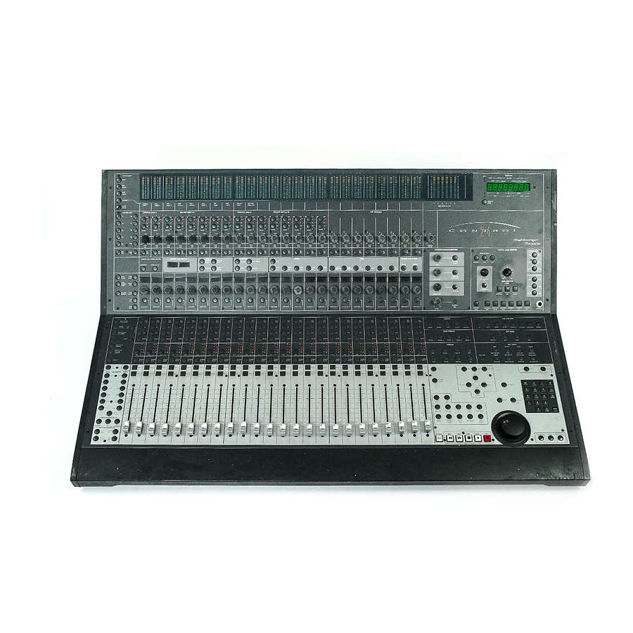
- Page 1 Control|24™...
- Page 2 Copyright Australian Compliance: © 2006 Digidesign, a division of Avid Technology, Inc. All rights reserved. This guide may not be duplicated in whole or in part without the express written consent of Digidesign. Avid, Control|24, Digidesign, DV Toolkit, DV Toolkit 2, Pro Tools, and Pro Tools LE are either trademarks or registered trademarks of Avid Technology, Inc.
- Page 3 • Do not attempt to service the equipment. There are no user-serviceable parts inside. Please refer all servicing to authorized Digidesign personnel. • Any attempt to service the equipment will expose you to a risk of electric shock, and will void the manufacturer’s warranty.
-
Page 5: Table Of Contents
About www.digidesign.com ........ - Page 6 Chapter 4. Mic and Line Preamps ..........21 Microphone and Line Preamps .
- Page 7 Talkback and Listenback ..........58 Chapter 9.
- Page 8 Part IV Applications Chapter 11. Recording ............87 Starting the Recording Process .
- Page 9 Chapter 13. Plug-Ins and Inserts ..........109 Using Plug-Ins in Real Time .
- Page 10 Appendix B. Utility Functions ..........131 Editing Parameters on UTILITY Pages .
-
Page 11: Part I Introduction
Part I: Introduction... -
Page 13: Chapter 1. Introduction To Control|24
Digidesign can only assure compatibility and Items included with Control|24 are: provide support for hardware and software it • Control|24 Console has tested and approved. For a list of Digidesign- • Control|24 Guide qualified computers, operating systems, and • 15-foot Crossover Ethernet cable third-party devices, refer to the Digidesign Web site (www.digidesign.com). -
Page 14: Ethernet Connections
1000baseT hubs. 100baseT and 1000baseT hubs individually for unique setups. must be “switching hubs” however, meaning they can recognize and adapt their operation to Visit the Digidesign Web site or your the 10baseT (the operating speed of Control|24 Digidesign dealer for DigiSnake details and communication). -
Page 15: Digidesign Registration
Control|24 hard- ware or Pro Tools session data. Conventions Used in This Guide Shortcuts show you useful keyboard or All Digidesign guides use the following conven- mouse shortcuts. tions to indicate menu choices and key com- mands:... -
Page 16: About Www.digidesign.com
Pro Tools Training Center. Products and Developers Learn about Digidesign products; download demo software; learn about our Development Partners and their plug-ins, applications, and hardware. News and Events Get the latest news from Digidesign; sign up for a Pro Tools demo. Control|24 Guide... -
Page 17: Chapter 2. Installing Control|24
Chapter 2: Installing Control|24 Installation and Maintenance Making Necessary Guidelines Connections Control|24 requires power and Ethernet connec- Before powering up your Control|24, be sure tions for basic communication and control of to allow it to reach room temperature, as Pro Tools. there are some components that are sensi- tive to cold temperatures. - Page 18 Pro Tools 7.1.x and lower, you must install these Ethernet connections should be made when drivers manually. Control|24 power is off. To install Digidesign Ethernet drivers for If Control|24 is the only Ethernet device Control|24: connected to your computer: Click Start, right-click My Network Places, and Connect one end of the included crossover then choose Properties.
- Page 19 About Control|24 and Ethernet Performance This section presents some general Ethernet concepts that will help optimize system perfor- mance. Control|24, Ethernet and Network Traffic If your computer is already connected to an Ethernet network, moderate network traffic (such as basic e-mail) should not affect commu- nication between Control|24 and Pro Tools.
- Page 20 Control|24 Guide...
-
Page 21: Part Ii Analog Connections
Part II: Analog Connections... -
Page 23: Chapter 3. Audio Connections
Chapter 3: Audio Connections This chapter provides an overview of Control|24 Input and Output Overview analog audio capabilities, and explains how to make all audio connections between Con- Control|24 offers a great deal of flexibility for trol|24, Pro Tools, and your other studio equip- routing audio to and from Pro Tools, other ex- ment for standard stereo operation. - Page 24 Control|24 Back Panel The Control|24 back panel provides the following connectors. Figure 1. Back panel connectors and switches PRO TOOLS MONITOR IN Provide up to eight 25-pin D-Sub Connectors channels of input to Control|24, to connect ste- The 25-pin D-Sub connectors provide access to reo or multichannel Pro Tools outputs for mon- the Contro|24 mic preamp outputs, and to most itoring and mixing through Control|24.
- Page 25 SUBMIXER 1–4 IN and SUBMIXER 5–8 IN Pro- EXTERNAL SOURCES IN Provide six channels (or vide eight stereo inputs for the Control|24 Line three stereo pairs) of additional, external sources Submixer. for monitoring. Use these for monitoring CD, DVD, or other audio sources in the Control SUBMIXER 1–4 IN Room Monitor section.
- Page 26 Output MONITOR SPEAKERS OUT Provides eight chan- nels of Control|24 output, to connect to speak- Three of the 25-pin D-Sub connectors provide ers for stereo and multichannel monitoring. output from Control|24 for recording and mon- These outputs are controlled by the Control itoring.
- Page 27 Additional I/O Connectors Output AUXILIARY OUTPUTS These two balanced, line- Control|24 provides the following individual level TRS outputs are for cue mixes, and should connectors on the back panel: be connected to the inputs of your cue system. Input SUBMIXER OUTPUTS These two line-level, bal- MIC and LINE Inputs These 16 balanced connec- anced TRS outputs carry the submix from the tors (XLR for Mic inputs, TRS for 1/4-inch in-...
-
Page 28: Stereo Monitoring Connections
Stereo Monitoring Connections Figure 2 shows connections for a basic stereo configuration. to line in 5–6 from AUX OUT L R Cue mix to MIC in 3–4 MONITOR D.I ch 1 SPEAKERS to PRO TOOLS MONITOR IN Pro Tools cue outs Pro Tools Out 1–2 to Pro Tools Inputs 1–8 Figure 2. - Page 29 Connections for Stereo Main and Alt Speaker Outputs Monitoring To connect stereo output from Control|24 for You can achieve a basic monitoring configura- monitoring: tion through Control|24 by using stereo mix Confirm that you have a 25-pin D-Sub con- playback in Pro Tools in conjunction with two nector that breaks out to the correct type of con- 25-pin D-Sub breakout cables (one for input and nectors for your patch bay or monitor system...
-
Page 30: Stereo And Surround Modes
Headphones The Line Submixer Section Control|24 provides a stereo headphone jack in The Control|24 built-in submixer consists of the Control Room Monitor section, with sepa- eight stereo input channels, which are sub- rate level control. The headphone jack provides mixed to the Control|24 stereo Submixer Master a discrete feed of the main stereo Control|24 control and output to the SUBMIXER OUT out- mix. -
Page 31: Chapter 4. Mic And Line Preamps
Chapter 4: Mic and Line Preamps Control|24 is equipped with 16 preamps for mi- Microphone and Line Preamps crophone or line-level signals. The first two in- put channels are also equipped with instru- All 16 input channels in Control|24 are switch- ment-level DI (direct input) inputs to able between microphone and line level opera- accommodate high impedance signals such as... -
Page 32: Preamp Connections
To connect an instrument-level signal: Preamp Connections Turn the level control all the way down (counter-clockwise) as a safety precaution. For manageability, route each preamp output to its corresponding input number on a Pro Tools Connect your Instrument source to the unbal- audio interface. -
Page 33: Using The Mic Preamps
Selecting a Preamp Source Using the Mic Preamps To choose a source input: The mic preamp controls are located along the top of the fader section. These controls include Push a preamp’s Source switch repeatedly un- source selection, variable gain, and a high-pass til the LED next to the type of input you would filter. -
Page 34: About Signal Levels
There are times when you want to avoid one ex- About Signal Levels treme more than the other, and certain soni- cally-pleasing textural results can be achieved Rule #1 in adjusting input gain is to never clip through the use of atypical gain structure. the signal in Pro Tools. -
Page 35: Chapter 5. Surround Setups
Chapter 5: Surround Setups 5.1 Surround Monitoring and Surround Monitoring Mode Control Room Options Connections The Control|24 Control Room section provides Control|24 supports multi-channel Surround level, source in/out, and solo/mute controls for monitoring modes to feed four-channel (LCRS) individual channels, channel pairs, and other or six-channel (5.1) monitoring systems. - Page 36 Pro Tools Film Track Layout L C R Ls Rs LFE 5.1 Formats Input connections for Film Pro Tools supports the following 5.1 format paths: Pro Tools Control|24: Pro Tools Signal Outputs Monitor Inputs • Film (Pro Tools default) • SMPTE/ITU (best for Control|24) •...
- Page 37 Options for Surround Mode Switching Reconnecting It is not always possible to remap paths in the Using I/O Setup I/O Setup dialog, as professional requirements To avoid having to re-patch, remap your 5.1 for- for professional surround mixing demand cor- mat paths in the Pro Tools I/O Setup dialog.
-
Page 38: 5.1 Monitoring Example
AUX OUT L R MONITOR SPEAKERS OUT C o n t r o l 2 4 C o n t r o l 2 4 digidesign digidesign Figure 3. Control|24 monitoring output connections for 5.1 mixing, SMPTE/ITU format Control|24 Guide... -
Page 39: Lcrs Monitoring Example
MONITOR SPEAKERS OUT C o n t r o l 2 4 C o n t r o l 2 4 digidesign digidesign Figure 4. Control|24 monitor output connections for LCRS mixing See also “5.1 Surround Monitoring and Control Room Options” on page 25. -
Page 40: 5.1 Track Layouts, Routing, And Metering
5.1 Track Layouts, Routing, and Metering Figure 5 shows the relationship between Pro Tools I/O Setup configurations, audio interface and channel meters when mixing in 5.1. Pro Tools on-screen 5.1 meters are always mapped according to the Film standard L, C, R, Ls, Rs, LFE. Output meters on Control|24 and Pro Tools audio interfaces, however, follow channel mapping in I/O Setup. - Page 41 1 2 3 4 5 6 PRO TOOLS SOURCES IN C o n t r o l 2 4 C o n t r o l 2 4 digidesign Surround monitoring from Pro Tools, SMPTE/ITU layout Chapter 5: Surround Setups...
- Page 42 Control|24 Guide...
-
Page 43: Part Iii Control|24 Basics
Part III: Control|24 Basics... -
Page 45: Chapter 6. Starting Up And Configuring Control|24
Chapter 6: Starting Up and Configuring Control|24 Shut down Pro Tools in this order: Starting Up and Shutting Turn off the monitoring amplifier and speaker Down a System system. Pro Tools systems components must be turned Turn off audio interfaces. on and shut off in a specific order. -
Page 46: Pro Tools Configuration
If Control|24 does not appear in the Ethernet Pro Tools Configuration Controllers pop-up menu, check the following: • Ethernet port status (Windows) Communication between Control|24 and • Ethernet port settings and connections. Pro Tools is configured from within the Ether- net Controllers page of the Pro Tools Peripherals •... -
Page 47: Quickstart System Test
QuickStart System Test Setup and Configuration Options This section takes you through a basic system test to make sure that hardware, software, and Control|24 provides the following monitoring connections are all configured and functioning modes and options, listed below with a descrip- properly. -
Page 48: Troubleshooting
Modal Dialog Messages Troubleshooting Pro Tools On-screen Dialog Warning This section includes information to assist you in troubleshooting Control|24. If a modal dialog message appears in Pro Tools, the following message will be displayed across Pro Tools Error Message: “Lost the scribble strips: “PRO TOOLS HAS A DIALOG ON SCREEN.”... -
Page 49: Chapter 7. Overview And Basics
Chapter 7: Overview and Basics This chapter provides an introduction to con- Controller Focus The term “controller focus” re- trol surface terminology, and an overview of the fers to the bank, track output, send, plug-in, or main sections and controls of Control|24. insert currently selected for editing by Con- trol|24. -
Page 50: Control|24 Sections
Control|24 Sections Meters Time Counter Fader Section Main Section Figure 1. Main sections of Control|24 There are three sections of Control|24, each Fader Section Contains all Control|24 fader with their own controls and subsections: strips, their controls, and other track controls such as input and output routing, insert and •... -
Page 51: Main Section Overview
Monitoring configurations can be selected and sent to multiple sets of speakers and head- phones. You can also route external sources (such as two-track return) or pairs of channels from your Digidesign audio interface. Transport Scrub/shuttle section Main section... - Page 52 Grouping, Zoom Presets, Window, Setup, and Inserts/Sends windows are all float- ing windows. If a floating window is already in and Edit Sections the foreground, then pressing its corresponding The Main section provides six sets of controls switch will close the window. for direct access to many Pro Tools grouping, zoom presets, window display, and edit com- Visibility of Plug-In Windows...
- Page 53 To undo: The Numeric Keypad Press the UNDO switch. The Numeric Keypad mirrors the function of the numeric keypad on the host computer, and is To redo: used for memory locations, data entry of counter values or numerics, for completing edit- Press SHIFT/ADD+ (CTRL)+UNDO.
- Page 54 To scroll controller focus one channel at a time: Home, Banks, and Controller Focus Press NUDGE to enable Nudge mode. In sessions with 25 tracks or more, the first 24 tracks (from the left side in the Mix window, or Press BANK RIGHT to scroll one channel to from the top of the Edit window) are the focus the right (for example, if Control|24 focus was...
-
Page 55: Transport Controls
Transport Controls Additional Transport Functions The following transport functions use the Control|24 provides the primary Transport con- trols, the Control section, and the Audition Back/Forward Amount preference, which is set in the Operations page of the Setup > Prefer- Control sections for complete transport control ences window. - Page 56 Control and Audition Sections • OPT(ALT)/ALL+IN or OUT: centers the left or right side of any current on-screen waveform Directly above the main Transport are the fol- selection in the Edit Window. lowing special function Transport controls: • (CTRL)+IN or OUT: enter mode for pre-roll and post-roll.
- Page 57 To enter an amount of pre- or post-roll: Audition Mode Shortcuts While pressing the (CTL) switch, press PRE To listen to the edit selection start point with both ROLL or POST ROLL. The respective switch LED pre- and post-roll: (PRE or POST) will flash, indicating that pre/post While pressing (CTL)+OPT(ALT)/ALL, press entry mode is active.
- Page 58 Transport Mode for Numeric Keypad ESC/CANCEL For additional flexibility, the numeric keypad There are two ESC/CANCEL switches on the can be configured for Transport command. Control|24 surface. The first ESC/CANCEL switch is located to the immediate right of the master ASSIGN switch in the Assign section of To engage Transport Mode for the numeric keypad: the Channel Bar.
-
Page 59: Fader Section Overview
Automation Section Fader Section Overview The controls in the Automation section let you The Fader section consists of the 24 Fader strips, enable Automation modes, select channel Auto- as well as other channel displays and controls. mation type, write, and suspend automation. (For details on the Fader strips, see Chapter 9, When the Demo Session starts, the correspond- “Working with Tracks.”) -
Page 60: Function Keys
Scribble Strips and Rotary The Channel Bar Display is an eight-character display located above the scribble strips of chan- Encoders nels 4 and 5. It displays the name of the current Each channel includes a rotary encoder for pa- track or parameter selected for editing. rameters such as pan, send level, and plug-in pa- rameters, with a scribble strip above the encode Channel Bar... -
Page 61: Meter Section Overview
Output Meters Mirror the first six Output meters meters. These switches select the mode of meter- of the primary Digidesign audio interface, show- ing for the 24 channel meters. ing the current Pro Tools Meter path as selected in the I/O Setup dialog. - Page 62 Control|24 Guide...
-
Page 63: Chapter 8. Control Room Monitor Section
Chapter 8: Control Room Monitor Section Control|24 includes the Control Room Monitor Control Room Monitor Overview section, and the Communications/Headphone The Control|24 Control Room Monitor section section. routes input from Pro Tools and other sources to Control|24 outputs for monitoring and routing. This analog section provides monitoring capa- Overview of Control|24 bilities for multiple sources and destinations,... -
Page 64: Stereo And Surround Monitoring Modes
Monitoring Single and Multiple Stereo and Surround Input Sources Monitoring Modes In Stereo Monitor mode, input can be set for sin- Control|24 can be used to monitor in Stereo gle source (default) or multi-source operation. mode, or in a supported multichannel Surround (In Surround modes, multi-source/discrete rout- modes (LCRS, and 5.1). -
Page 65: Selecting Monitor Modes
Monitor Input Source Select Selecting Monitor Modes Switches Control|24 supports Stereo, LCRS, and 5.1 Sur- The Control Room Monitor section comprises a round modes. set of six possible stereo monitor sources for Control|24 in stereo mode, or as master source controls for the matrix inputs in Surround Stereo Mode Settings mode. -
Page 66: Control Room Monitor Level Controls
MONITOR TO AUX and AUX LEVEL Calibrating Monitor Systems for Control|24 Monitor Output Level To achieve the best performance from the MAIN MONITOR LEVEL control, set your monitor power amplifier (or powered monitor gain) so that reasonably loud (but not excessively loud) monitor levels are achieved when the MAIN Monitor To Aux MONITOR LEVEL control is at approximately... - Page 67 The MUTE ALL switch acts as a Control Room Alt Monitor in Surround Modes Monitor master mute. The MUTE switch does When ALT Monitor is selected in Surround not affect the Headphone signal (front-panel Monitor modes, only the Left and Right chan- 1/4-inch connector), but mutes all other sources nels are routed to the ALT outputs.
-
Page 68: Talkback And Listenback
DIM Switch Headphone Jack and Controls The DIM switch inserts a 20 dB reduction in A 1/4-inch stereo jack is provided on the Con- level to the Control Room Monitor outputs. De- trol|24 front-panel for headphone monitoring pending on monitoring mode, most of the out- of the currently active main Control Room puts are affected. - Page 69 control room outputs are muted. Pressing the External Talkback Input Listenback switch again toggles the Listenback For higher-fidelity or remote Talkback, an exter- circuit off, and the control room outputs are re- nal XLR Talkback input is provided on the Con- activated.
- Page 70 Using Talkback Using Listenback Whether using the internal or external micro- To enable the Listenback microphone: phones, operation of the TALKBACK switch is Press the Utility switch. the same. Select “Monitor.” To use Talkback: Select “Talkback.” Press and hold the TALKBACK switch. This If flashing, select “Listenback.”...
-
Page 71: Chapter 9. Working With Tracks
Chapter 9: Working with Tracks This chapter describes the components of the The Control|24 fader section shows a printed fader section, and explains each function in scale to +6 dB. However, when Fader Gain is set channel-specific tasks. to +12 dB in Pro Tools, the appropriate volume levels are shown in the Control|24 Channel Scribble Strips. -
Page 72: Scribble Strips
Scribble Strips Mute and Solo Functions Each of the twenty-four channels has its own MUTE and SOLO switches are located above the four-character scribble strip display. These dis- fader on each channel. The on-screen mute and plays often identify names or settings related to solo functions are equivalent to those on Con- their respective channel strip. - Page 73 Shortcuts Solo and Record Safe Modes APPLY TO ALL CHANNELS+MUTE or SOLO: Channel strips can be placed into Solo and clears or enables Mutes or Solos on all channels. Record Safe modes. When in these safe modes, channels are locked out from implied mute or APPLY TO ALL SELECTED CHANNELS+MUTE record states, respectively.
-
Page 74: The Select Switch
To enable Record Safe status on a channel strip: The SELECT Switch Press the RECORD SAFE switch. Its LED will flash. The SELECT switches select channels for group- ing, deletion and all other channel-related func- Press the REC ARM switch on any channels tions that do not have dedicated controls on the you would like to place in Record Safe mode. -
Page 75: Channel Automation Controls
The channel AUTO switch can also be used in Channel Automation Controls combination with the master AUTOMATION MODE and ENABLE switches. The AUTO switch is located above the SELECT switch. Next to this are five Automation mode LED indicators. The AUTO switch is used to set channel automa- tion mode, and to punch out of automation re- cording on a channel during an automation record pass (placing the channel in Read mode). -
Page 76: Data Encoder And Led Rings
Velocity Sensitivity Data Encoder and LED Rings By default, the data encoders are in a fixed-ve- Directly below the scribble strip on each chan- locity mode, that emulates the feel of analog nel is a Data Encoder knob (surrounded by a pots. -
Page 77: Pan/Send Switch
Master EDIT/BYP Switch PAN/SEND Switch The EDIT/BYP switch is located immediately to The PAN/SEND switch invokes Pan/Send mode, the left of the channel EQ switch row. It toggles that displays all of the track’s pan and sends in- the function of the EQ and DYN switches be- formation across the scribble strips. -
Page 78: Inserts Switch
EQ BYP Mode and DYN BYP Mode For more detailed information on insert effects editing and routing, see Chapter 13, “Plug-Ins When in Bypass mode (EDIT/BYP switch LED and Inserts.” on), the channel EQ and DYN switches serve as bypass switches for all EQ or Dynamics plug-ins assigned to a channel. -
Page 79: Default Quickmode Switch
Shortcuts employing the MASTER REC switch: To reset all selected faders or encoders to their default setting: • Press MASTER REC to record-enable all audio While pressing DEFAULT+APPLY TO ALL SE- tracks. LECTED CHANNELS, press any channel’s SE- • While pressing APPLY TO ALL SELECTED LECT switch. -
Page 80: The Groups Section
To paste copied settings to the current Target Creating New Groups plug-in: The CREATE switch is used to create groups in Select the plug-in into which you want to empty group locations, or overwrite existing paste settings. This must be the same plug-in groups: that you copied from, on a different track or in- sert position. - Page 81 Enabling/Disabling Groups Suspending Groups ENABLE lets you enable or suspend groups. The SUSPEND groups switch lets you tempo- rarily suspend groups. To enable or suspend a group or groups: To suspend all groups: Press ENABLE. Press the SUSPEND switch. The corresponding A dialog across the scribble strips prompts you LED will flash to indicate that all groups are dis- to select a group to enable or disable from the...
- Page 82 Control|24 Guide...
-
Page 83: Chapter 10. Navigation And Editing
Chapter 10: Navigation and Editing This chapter describes how to navigate through Navigation Mode a session and how to edit audio and MIDI with The Navigation functions are equivalent to the Control|24. four arrow keys on the alpha-numeric key- board— that are used for basic navigation within the various windows—except when nav- Navigation and Zoom igating selections. -
Page 84: Scrub/Shuttle Wheel
Using Scrub Mode Scrub/Shuttle Wheel To use Scrub mode: The Scrub/Shuttle wheel is used for scrubbing, shuttling, defining regions, and other edit oper- Press SCRUB while Pro Tools is not playing or ations. recording. Navigate the scrub point to the start or end of a current selection by pressing PREVIOUS (for start) or NEXT (for end). - Page 85 Rotate the shuttle wheel clockwise to shuttle Scrub with Trim audio forward, or counter-clockwise to shuttle Control|24 supports Trim/Scrub mode, which backward. The REW and FWD switch LEDs will lets you scrub to locate an edit point, then trim light (just like the on-screen Transport buttons to that point in one operation.
- Page 86 Shuttle Mode Shortcuts Navigating and Editing with the Scrub/Shuttle Wheel To engage Shuttle mode for the numeric keypad: The primary function of the Scrub/Shuttle Choose Setups > Preferences > Operations. wheel is listening at variable speeds (crawling slowly for precise editing or scanning a track in Enable the Shuttle mode Numeric Keypad op- high-speed mode to search for elements).
-
Page 87: Zoom Mode
Scrub the in or out point with the Scrub/Shut- To adjust the perceived amplitude of a waveform in the Edit window: tle wheel while pressing SHIFT/ADD, depending on whether you selected PREVOIUS or NEXT. Press UP or DOWN to exaggerate or minimize Your selection will expand/contract with the the waveform amplitude. -
Page 88: Creating On-Screen Selections
To create a memory location with a specific Creating Selections Using numerical address: Memory Locations Enter a decimal, a number key (or keys), then Here are a few more techniques for making se- press ENTER. lections. If available, a memory location will be assigned To create a selection using two memory locations to that number/address. -
Page 89: Sel Adj Mode
To make a selection “on the fly” during playback: Using the Selection Indicators Click within the desired track to select it. The Selection Indicators let you define selec- tions numerically, to make precise selections Press PLAY. based on specific time locations in a session. As your track plays, press the IN switch to set the selection start. -
Page 90: Link/Unlink Edit And Timeline
To select and adjust the selections OUT point: Window Navigation Key While pressing the NEXT switch, rotate the Commands Scrub/Shuttle wheel. The following key commands are active in all You can move the entire selection forward or three of the modes (NAV, ZOOM, and SEL ADJ): backwards against the Pro Tools timeline while maintaining the selection length. -
Page 91: Creating And Editing Regions
Creating and Editing Regions Separating Regions The Control|24 Edit tools include all the con- To separate a new region with the Separate trols found in the Edit Mode, Edit Tool, and Edit Region command: Function sections. The switches mirror their Select the portion of the waveform that you functions in Pro Tools. -
Page 92: Edit Tool Selection
To extend the selection to next/previous regions: Edit Tool Selection Place the edit cursor in the playlist of the de- sired track, or select a region in that track, while The Trimmer, Grabber, and Pencil each have in Navigation mode. different tool options available from their pop- up menus in the Edit window in Pro Tools. -
Page 93: Nudging Regions
Nudging Regions Editing Waveforms with the Pencil Tool You can move regions in precise, user-selectable Grid increments with the plus (+) and minus (–) The Pencil tool enables you to destructively “re- keys on the Control|24 Numeric Keypad. draw” audio waveform data, automation and MIDI note and controller data. - Page 94 Control|24 Guide...
- Page 95 Part IV: Applications...
-
Page 97: Chapter 11. Recording
Chapter 11: Recording This chapter explains all the steps required to To assign an audio channel input from “home” or Sends mode: record into Pro Tools using Control|24. Instruc- tions include configuring session parameters, Press ASSIGN. The ASSIGN and ESC/CANCEL assigning input and output routing, record-en- switches will both flash. -
Page 98: Assigning Outputs
To make the same input assignment to all Displaying Input Assignments: channels simultaneously: You can easily check input or output assignment Press APPLY TO ALL CHANNELS or at any time. OPT(ALT)/ALL while confirming your selection. When viewing input, output, or insert routing, Using the above procedure to select “none”... -
Page 99: Assigning Midi Outputs
To make the same output assignment to all To assign multiple outputs: channels simultaneously: While pressing CTL/CLUTCH, while assign- Press APPLY TO ALL CHANNELS or ing an output to a track. OPT(ALT)/ALL while assigning an output to a track. TrackInput Monitoring To make the same output assignment to selected channels only: TrackInput monitoring lets you toggle individ-... -
Page 100: Record Modes
Press the PAN/SEND switch on any channel to MIDI Record modes Merge/Replace, Wait For exit Select Input Monitoring mode. Note, MIDI Loop Record, and MIDI Merge Loop Record are the MIDI recording modes. On Control|24, the SWITCH ACTIVE switch lights to indicate Input Only mode. On-screen, Click and Countoff options are also available in the Track Input button lights green to indicate audio and MIDI recording. -
Page 101: Midi Recording Modes
The channel REC ARM switch LED will flash MIDI Recording Modes when a channel is in Record-Ready mode and lights solid when Pro Tools enters record (record By default, when the MERGE REC switch LED is mode). not lit, MIDI recording is in Replace mode. To arm Pro Tools for recording: Merge and Replace Press the RECORD switch in the Control|24... -
Page 102: Recording
To toggle all MIDI tracks in or out of Record-Ready RECORD and PLAY will both stay lit for the du- mode, do one of the following: ration of the recording pass. You can stop re- cording at any time by pressing STOP (or by While pressing APPLY TO ALL CHANNELS, pressing the Space bar on your computer key- press REC ARM on any active MIDI track. -
Page 103: Loop Record Mode
MIDI Merge Loop Recording is similar to a Shortcuts “drum machine” style of recording. The loop merges with previously recorded to create a To change record-enable status on all channels, do one of the following: composite of several loop cycles. This enables you (for example) to record hi-hats on the first While pressing APPLY TO ALL CHANNELS, pass and kick and snare on the next. -
Page 104: Quickpunch Recording
To enable MIDI Merge Loop Recording mode: QuickPunch Recording Press the MIDI TOOLS switch. The LED while light up. QuickPunch lets you instantaneously punch in (start recording) and punch out (stop recording) Press MERGE REC. on record-enabled audio tracks during playback Press the LOOP PLAY switch located just by pressing the RECORD switch in the trans- above the primary Transport switches. -
Page 105: Trackpunch Recording
When TrackPunch mode is enabled: TrackPunch Recording A “T” appears in the on-screen Transport Record button. TrackPunch lets you instantaneously punch in (start recording) and punch out (stop recording) If at least one track is TrackPunch-enabled, on individual audio tracks during playback. You the on-screen Transport Record button lights can punch in on a TrackPunch-enabled track at solid blue. - Page 106 TrackPunch Enabling Tracks To simultaneously TrackPunch enable and record enable all selected audio tracks: While in TrackPunch mode, you can Track- Hold the SHIFT/ADD + OPT (ALT) ALL Punch enable tracks without record enabling switches and press a selected track’s REC ARM them, which lets you punch in individual tracks switch to toggle the on-screen Record Enable after you start playback.
- Page 107 TrackPunch Recording Punching In on Multiple Tracks After you have put Pro Tools in TrackPunch To punch in on multiple tracks simultaneously: mode and enabled tracks for TrackPunch record- Put Pro Tools in TrackPunch mode. ing, you can record with TrackPunch in several ways.
-
Page 108: Setting Up Cue Mixes
Assign the send outputs to the output pair Setting Up Cue Mixes patched to the Control|24 AUX IN buss. The Control|24 AUX OUT outputs can be con- Once your mix is set up pre-fader, you can copy nected to your cue mix system to provide a your current (main) fader mix to your newly- headphone mix. -
Page 109: Footswitch Shortcuts
Footswitch Shortcuts Footswitch behavior is selected in Utilities mode. The default is PLAY, but there are other options available, such as record and talkback. When either footswitch is employed, the fol- lowing shortcuts are available: To cancel a record pass: Hold down SHIFT/ADD and press Footswitch #1 to cancel the recording without saving the most recent recording. - Page 110 Control|24 Guide...
-
Page 111: Chapter 12. Mixing
Chapter 12: Mixing Control|24 provides comprehensive support for Although the routing and configuring of MIDI the Pro Tools mix environment. This includes tracks differs in various ways from the way it is the ability to access and control input and out- done with audio, a MIDI track will appear and put configurations, inserts, sends, auxiliary in- function in basically the same way as an audio... -
Page 112: Instrument Tracks
The scribble strip for each track display default The following MIDI controls appear on each (or previously-assigned) input assignments. channel as follows: • Channel data encoder: MIDI Volume Adjust the data encoder knob to scroll • Select switch: MIDI Mute through the list of available inputs on each track you want to configure. -
Page 113: Sends
The NUDGE switch will light if there are more On each channel where you want to assign a than 24 Master Faders in the session. If neces- send, turn the channel data encoder to scroll sary, press BANK RIGHT or BANK LEFT to bring through the available path choices. - Page 114 When you have confirmed a send assignment, To assign a Send from Pan/Send mode: the SWITCH ACTIVE LEDs will light up below Press the PAN/SEND switch on a channel to the encoder switches that correspond to that display its Sends in the Channel Bar. send’s destination and the panning information To page the Channel Bar display between should show up in the scribble strips.
- Page 115 While holding CTL/CLUTCH, press the en- To make the same assignment to all channels simultaneously: coder’s flashing switch to make the additional output assignment. Press the PAN/SEND switch on a channel. Press the ASSIGN switch in the ASSIGNMENT Displaying Send Assignments section.
-
Page 116: Using Flip Mode With Sends
Press the SEND MUTE switch. Its LED will To toggle a send between pre- and post-fader status for all selected channels: light, indicating that you are in Send Mute mode. Make sure playback is stopped, and that Con- trol|24 is not in channel ASSIGN mode (the AS- Press an encoder switch on a channel to mute SIGN switch LED should be off). - Page 117 Send Pan Send Mute In Flip mode, the channel encoders are used to In Send Flip mode, the channel MUTE switches display and adjust pan position for stereo sends. become SEND MUTE controls. The channel encoder LED ring displays the rela- Pre/Post Toggling tive position of the PAN control.
-
Page 118: Flip Mode Applications
You can exit Flip mode at any time and return to Send Shortcuts normal operation by pressing the flashing FLIP switch. This action will return Control|24 to the To toggle a send between pre- and post-fader state it was in prior to entering Flip. The FLIP status for all channels: switch LED will extinguish when the mode is Follow steps 1 through 4 above. -
Page 119: Chapter 13. Plug-Ins And Inserts
Chapter 13: Plug-Ins and Inserts Using Plug-Ins in Real Time INSERTS Section Control|24 provides complete access and con- Located to the right of the channel bar display is trol to the five inserts on each Audio Track, Aux- the INSERTS section, that contains four iliary Input track, or Master Fader. -
Page 120: Assigning A Plug-In
MASTER BYPASS Switch Press the master ASSIGN switch, located in the ASSIGN section of the CHANNEL BAR. The The MASTER BYPASS switch has two functions, switch LED will flash, indicating that ASSIGN depending on the current state of the IN- mode is now active. -
Page 121: Editing Plug-Ins
The selected plug-in will be instantiated in the To assign a plug-in to all tracks simultaneously: same insert position across all selected channels. Assign plug-ins as described above. When scrolling through input, output, or in- Before confirming the assignment, do one of sert options, the currently selected assign- the following steps: ments will be indicated by a “>“symbol in... - Page 122 Press the channel’s INSERT switch again to re- Multi-Mono Plug-In A multi-mono plug-in is in- turn to the Control|24 default mode. The scrib- dicated by a raised “.” in front of the plug-in ble strips will display track names, the encoders name.
-
Page 123: Eq And Dyn Switches And Modes
AUTO/SELECT Switch uration of the global EDIT/BYP switch. In Parameters mode, the AUTO/SELECT switch The EQ switch is supported by all Digidesign enables encoder switches to toggle their focused and Digidesign-distributed EQ plug-ins, and the plug-in in or out. In this mode, the AUTO/SE- DYN switch affects most compressor, gate, and LECT switch LED will not be lit. -
Page 124: The Default Switch
systematically by track or effect type, that can The DEFAULT Switch save time and keep you from having to look away from the Control|24 surface or leave the The DEFAULT switch serves as a shortcut alter- monitors’ sweet spot. native to using the channel encoder knobs to re- move a plug-in. -
Page 125: Copying And Pasting Plug-In Settings
Navigating Between Plug-In Targets Copying and Pasting Plug-In If you open a new plug-in from Control|24 with- Settings out pressing the SHIFT/ADD switch, the newly- Settings can be copied from one plug-in instan- opened plug-in will become the new Target. The tiation and pasted into another with dedicated previous Target, if any, will replaced by the new commands from Control|24. -
Page 126: Plug-In Flip Mode
To open a the current controller focus plug-in Plug-In Safe Mode window: Press the unlit PLUG-IN switch. Pro Tools provides a Plug-In Safe mode to keep a plug-in’s automation data from being overwrit- To close the current controller focus plug-in ten. -
Page 127: Chapter 14. Automation
Chapter 14: Automation This chapter will explain how to maximize and Recording Mix Automation expand the capabilities of Pro Tools mix auto- mation with Control|24. Control|24 replicates Pro Tools on-screen auto- mation features, with channel-based and ses- sion-wide automation controls. Automation Mode Channel Automation Switches You can set the Automation mode for all tracks,... - Page 128 AUTOMATION ENABLE Switches Suspending Automation Control|24 AUTOMATION ENABLE switches, This switch is located directly below the Auto- located to the left of the channel faders, are mation mode and Enable switches. The AUTO identical to those found in the Pro Tools Auto- SUSPEND switch globally suspends record and mation Enable window.
-
Page 129: Recording Volume, Pan, Or Mute Automation
Groups and Automation Mode To arm or disarm the MASTER BYPASS function: Assignment While pressing OPT(ALT)/ALL, press the MAS- TER BYPASS switch in the CHANNEL BAR. As in Pro Tools, groups follow Automation mode assignments. The switch LED will either light solid, or flash, depending on which Automation mode has To suppress Group behavior during automation been set, and the CHANNEL BAR DISPLAY will... - Page 130 AutoMatch Function Join Function During playback, you can stop writing of auto- The Join function is used in Latch mode to man- mation on Write-enabled or Latch-enabled ually resume writing of automation after the tracks and return automation to previously writ- transport is stopped and started again during an ten levels by ramping up or down according to automation pass.
-
Page 131: Automating Sends
Move the cursor back so that it is just before To automate Send Mute: the stop location. Make sure SEND MUTE automation is en- abled. Resume playback. Select a SEND by pressing the relevant master At the AutoJoin Indicator, automation record- SEND switches (A/F–E/J). -
Page 132: Enabling Trim Mode
About Groups and Automation Mode Enabling Trim Mode Assignment Trim is a special mode for the three write modes As in Pro Tools, Automation mode assignment (Write, Touch and Latch). It is toggled on/off follows Groups. separately from other automation mode opera- tions. - Page 133 Control|24 enables you use the Write Automa- While still playing back during or immedi- tion to Start/All/End functions with all automa- ately after making your adjustments, press tion recording modes including Write, Touch WRITE AUTOMATION TO+START (or, +ALL, or, and Latch, and the Trim modes. +END).
-
Page 134: Automating Plug-Ins
To configure Automation Write On Stop modes to You can punch-out of automation recording remain enabled after an automation pass: at any time by pressing the appropriate AUTO- MATION ENABLE switch. While holding CTL/CLUTCH and OPT(ALT)/ALL, press the START, END, or ALL If you want to add additional automation switch in the WRITE AUTOMATION TO section. -
Page 135: Automating Plug-In Flip Mode
To disable a plug-in parameter from automation: Select the desired plug-in to make it the con- troller focus. Press the AUTO/SELECT switch. Press the encoder switches below the parame- ter names in the scribble strips that you want to suspend from automation. Pressing a lit parameter encoder switch will toggle the automation arming off. - Page 136 Control|24 Guide...
-
Page 137: Appendix A. Pinout Tables
Appendix A: Pinout Tables Mic/Line Outputs 9–16 25-Pin Female D-Subs Channels 9–16 Mic/Line Preamp Outputs Mic/Line Outputs 1–8 Channel Hot (+) Cold (–) Ground (shield) Channels 1–8 Mic/Line Preamp Outputs Channel Hot (+) Cold (–) Ground (shield) Appendix A: Pinout Tables... - Page 138 Line Submixer 1–4 Inputs External Source Inputs Channels 1–4 Line Submixer Inputs External Source (Monitor) Inputs Ground Ground Channel Hot (+) Cold (–) Channel Hot (+) Cold (–) (shield) (shield) 1 Left 1 Left 1 Right 1 Right 2 Left 2 Left (Center) 2 Right 2 Right...
-
Page 139: Xlr And Trs Connectors
Monitor Outputs Pro Tools Monitor Inputs Ground Channel Hot (+) Cold (–) (shield) Left Right Center Surround, Sub Left Surround Right Surround Alt Monitor Left Alt Monitor Right XLR and TRS Connectors XLR Mic Inputs Ground Channel Hot (+) Cold (–) (shield) all XLR Mic Inputs (female) - Page 140 Control|24 Guide...
-
Page 141: Appendix B. Utility Functions
Appendix B: Utility Functions The UTILITY functions let you configure opera- Editing Parameters on UTILITY tional aspects of Control|24, and to perform di- Pages agnostic tests on surface components. When editing parameter choices on the UTIL- To enter the UTILITY menu: ITY pages, you can make menu choice changes Press the UTILITY switch (located directly as follows:... -
Page 142: Sys Info Page
Talkback Page Sys Info Page This mode allows you to specify the settings for The Sys Info page contains information about talkback mic operation. It provides a way to se- the hardware and firmware revisions on Con- lect whether the internally-mounted talkback trol|24, as well as the Ethernet ID. -
Page 143: Vegas Mode
Vegas Mode Test Modes for LED Colors Vegas mode rapidly turns each switch LED, Red LED mode, Yellow LED mode, and Green meter segment, and 7-segment display LED on LED mode, are used to check for proper lighting and off in a randomized fashion. The faders are of all LEDs of the specified color on the control also run in sine wave mode. -
Page 144: All Led Test Mode
The scribble strips located to the right of the dis- All LED Test Mode play that shows “Exit” will be left blank. Since none of the choices are shown as a “default” se- All LED mode, when engaged, checks for proper lection as is the case in other UTILITY menus, all lighting of all LEDs on the control surface by encoder switch LEDs below each menu item will... -
Page 145: Timecode Display Test Mode
Timecode Display Test Mode Scribble Strip Test Mode Timecode display test mode will continually cy- Scribble strip test mode will continually cycle cle through a series of automated tests which through a series of automated tests which check check the LEDs and LED segments on the time the segments on the LCD scribble strips. -
Page 146: Fader Test Pages
Step Test Mode Fader Test Pages Step test mode places the faders on Control|24 The Fader test mode allows you to test the oper- in a test mode where the faders jump, lock-step, ation of the touch sensing, moving faders on to fader positions which are determined by ad- Control|24. - Page 147 Cycle Test Mode Sine Test Mode Cycle test mode places the faders on Control|24 Sine test mode places the faders on Control|24 in a test mode where the faders cycle, lock-step, in a test mode where the faders cycle, in a sine from the bottom of the fader throw to the top in wave shape, from the bottom of the fader throw a continuos cycle.
- Page 148 Group Test Mode Touch Test Mode Group test mode places the faders on Control|24 Touch test mode places the faders in a test mode in a test mode where the faders become grouped where the scribble strips indicate when a fader and can be moved, lock-step, to indicate that all has been touched and at what frequency the faders are operating properly in a grouped fash-...
-
Page 149: Footswitch Pages
Rotary Test Page Footswitch Pages The Rotary test page provides you with a way to check the operation of all rotary encoders on About Polarity Control|24. This includes the SCRUB/SHUTTLE wheel. This test does not include the mic-pre or The Polarity + choice is the default but its asso- submixer analog pots. -
Page 150: Sys Reset Page
To access footswitch SW1 settings: Sys Reset Page Press the flashing encoder switch below the label “SW1.” The Sys Reset page allows you to reset Con- trol|24 to the factory default settings. The text label “SW1” will be displayed on the far right dual 4-character scribble strip display in To reset Control|24: the CHANNEL BAR. -
Page 151: System Diagnostics
“Welcome to Con- involving loop-back. In this way, the customer, trol|24.” or Digidesign Customer Service, can confirm • If communication has been enabled between that a customer’s Control|24 is fully functional. Control|24 and Pro Tools in the Pro Tools Pe-... - Page 152 Control|24 Guide...
-
Page 153: Index
index Symbols automation 117 and Plug-Ins 124 @ 112 Auto Join function 120 AutoMatch function 120 Numerics editing 121 10Base-T 8 enabling 118, 124 15 dB (DIM) 58 groups 122 5.1 54 Join function 120 modes 117 Plug-Ins 124 punching out 122 Apply To All Channels 49 recording volume, pan and mute 119 Apply To Selected Channels 49... - Page 154 Ethernet 3 and zones 9 Channel Bar 50 bridges 36 cleaning 7 connections 8 CMD/CTRL switch 49 drivers 8 configuring Pro Tools 36 drivers (Windows XP) 8 Control|24 performance tips 9 and signal routing 101 EXT TRANS switch 46, 47 system requirements 3 external devices 47 controller focus 39, 114...
- Page 155 IN switch 46, 47 machines, external see EXT TRANS 47 inactive indicator 112 maintenance 7 Input Only mode 89 markers 77 INPUT switch 66 MASTER BYPASS switch 110 inputs Master Faders 102 alternate sources 19 assigning 87, 88 MEM-LOC switch 42 INS/BYP switch 68 MEM-LOC switch (window display) 42 Inserts...
- Page 156 Plug-Ins 109 assigning 110 NAV (navigating) 73 assigning inputs from 88 Navigation mode 73 automating 124 network 4 automating in Flip mode 125 NEXT switch (navigation) 73 displaying in channels 112 NUDGE switch 44 editing 111 and Master Faders 103 Flip mode 116 nudging 83 inactive (@) 112...
- Page 157 Serial Machine 47 Session Setup window 87 SAVE switch 42 SHIFT/ADD switch 49 scribble strips (channel displays) 62 SHOW CHANNEL NAMES switch 50 SCRUB SHOW VALUES switch 50 fine control 74 SHUFFLE switch 82 Scrub with Trim 75 SHUTTLE 75 scrub/shuttle editing 76 Shuttle Lock mode 75...
- Page 158 Talkback 58, 59 TALKBACK switch 60 target (Plug-In window) 114 TOOL switch 82 TOUCH switch 118 TrackInput monitoring 89 TrackPunch 95, 97 tracks Auxiliary Inputs 101 Master Faders 102 TRANS switch (window display) 42 Transport 41, 45 Back/Forward functions 45 mode for numeric keypad 48 Shuttle mode 76 Special Function switches 46...
- Page 159 DIGIDESIGN TECHNICAL SUPPORT (USA) PRODUCT INFORMATION (USA) INTERNATIONAL OFFICES Visit our Digidesign Web site 2001 Junipero Serra Boulevard Tel: 650.731.6100 Tel: 650.731.6102 for contact information Daly City, CA 94014-3886 USA Fax: 650.731.6384 Fax: 800.333.2137 Tel: 650.731.6300 Fax: 650.731.6399...
Need help?
Do you have a question about the Control 24 and is the answer not in the manual?
Questions and answers