Table of Contents
Advertisement
Quick Links
D-Show
Profile Guide
™
Version 2.5 for VENUE Systems
Digidesign
2001 Junipero Serra Boulevard
Daly City, CA 94014-3886 USA
tel: 650·731·6300
fax: 650·731·6399
Technical Support (USA)
tel: 650·731·6100
fax: 650·731·6384
Product Information (USA)
tel: 650-731-6102
International Offices
Visit the Digidesign website
for contact information
Website
www.digidesign.com
Advertisement
Table of Contents

Subscribe to Our Youtube Channel
Related Manuals for DigiDesign D-Show Profile


Summary of Contents for DigiDesign D-Show Profile
- Page 1 Version 2.5 for VENUE Systems Digidesign 2001 Junipero Serra Boulevard Daly City, CA 94014-3886 USA tel: 650·731·6300 fax: 650·731·6399 Technical Support (USA) tel: 650·731·6100 fax: 650·731·6384 Product Information (USA) tel: 650-731-6102 International Offices Visit the Digidesign website for contact information Website www.digidesign.com...
- Page 2 4) Follow all instructions. Compliance Statement 5) Do not use this apparatus near water. The models D-Show Profile, D-Show FOH Rack, and D-Show Stage Rack comply with the following standards regulating emissions and immunity: 6) Clean only with dry cloth.
-
Page 3: Table Of Contents
Assembling and Attaching the Video Monitor Mount to D-Show Profile ....... - Page 4 Chapter 4. Basic Commands and Modes ............35 Control Overview .
- Page 5 Chapter 8. Outputs and Output Routing ............69 Configuring Outputs.
- Page 6 Chapter 13. Metering ................107 Channel Meters .
- Page 7 Snapshot Controls on the D-Show Profile Control Surface ....... . .
- Page 8 D-Show Profile Console ........
- Page 9 D-Show Profile Power and Status LEDs ........
- Page 10 D-Show Profile Guide...
-
Page 11: Part I Overview And Installation
Part I: Overview and Installation... -
Page 13: Chapter 1. D-Show Profile System Introduction
Chapter 1: D-Show Profile System Introduction Welcome to the D-Show™ Profile live sound mixing console FOH Rack from Digidesign®. D-Show Profile is part of Digidesign’s mod- • 8 channels of analog I/O for connecting outboard equip- ular VENUE live sound environment. -
Page 14: D-Show Expansion Options
D-Show Expansion Options The Ethernet Expansion card allows remote control of all con- The following options can be added to a D-Show Profile sys- sole functions using a standard wired or wireless Ethernet con- tem. For details on D-Show expansion and customization op- nection. -
Page 15: Operational Requirements
Temperature and Ventilation Power Connections D-Show units should be operated away from heat sources and Each D-Show unit (D-Show Profile, FOH Rack, Stage Rack, and with adequate ventilation. PQ Rack (if any)) requires its own power connections for pri- mary and redundant power. - Page 16 D-Show Profile Guide...
-
Page 17: Chapter 2. Configuring And Connecting D-Show
To complete the assembly, remove the 4 mounting screws from the back of the D-Show Profile includes a Video Monitor Mount for your VGA video monitor, line up the holes of the mounting plate, and monitor. - Page 18 Hold the mounting arm face down so that the narrow (top) Loosen the screws holding monitor (or the U bracket) to the end is against the back of the U bracket. Make sure the arm is mounting arm, and slide it down or up to the desired height. facing the correct way, and attach the arm to the U bracket us- Tighten all screws to secure the monitor in its new position.
-
Page 19: Back Panel Connectors
Reconnect USB and headphones to the front panel ports. FOH Link Removing and Attaching the Trackball Mount FOH Link connects D-Show Profile to the FOH Rack. One FOH Link cable is included with each FOH Rack. The Trackball Mount can be removed quickly before packing or storing the console. -
Page 20: Connecting D-Show Components
Connecting D-Show Components D-Show Profile FOH Link Cable 2TR AES 2TR SPDIF MIDI TB Gain Analog Out +4 dBu Mon Left 2TR Out Analog In AES SPDIF +4 dBu Mon Right 2TR In AES 1 2 AES 3 4 AES 5 6... - Page 21 Connecting D-Show Profile to the FOH Rack The D-Show Profile control surface is connected to the FOH Rack with the provided FOH Link cable. To connect the control surface and the FOH Rack: Connect one end of the FOH Link cable to the FOH Link port on the back panel of the D-Show Profile control surface. Connect ■...
- Page 22 Connecting the Stage Rack to the FOH Rack The Stage Rack is connected to the FOH Rack with the Digital Snake cable (purchased separately). To connect the Stage Rack to the FOH Rack: On the Stage Rack, connect the Digital Snake cable lead with the white connector sleeve to the Snake 1 In port (this port label is outlined in white), and the Digital Snake cable lead with the red connector sleeve to the Snake 1 Out port.
-
Page 23: Connecting A Second Stage Rack
Connecting a Second Stage Rack Before connecting a second stage rack to a D-Show system, a second Snake card (purchased separately) must first be installed in the FOH Rack. To connect a second Stage Rack: Install a second Snake card in the FOH Rack. See the documentation that came with the Snake card. Using a BNC cable (included with the additional Snake card), connect the Word Clock Out port on the first Snake card to the Word Clock In port on the second Snake card. -
Page 24: Power Connections
Power Connections Each power supply in the D-Show Profile control surface, the FOH Rack, and the Stage Rack requires its own power connection. (Units that include a redundant power supply require two dedicated power connections.) Each power supply is auto voltage-se- lecting (100V to 240V). - Page 25 Digital Audio Inputs (Optional DSI Card) Digital Inputs and Sample Rate Conversion The DSI card operates at the D-Show system sample rate of 48 kHz. The DSI card provides auto-detection and sample rate (XLR3-F Connectors) conversion on input, letting you connect a wide variety of digital sources without having to be concerned with synchro- •...
- Page 26 Auto-Detecting Synchronizing External Digital Source Devices The DSI card automatically detects whether an external device When an external device is running at 48 kHz and clocked to connected to a DSI input is synchronized to the D-Show sys- D-Show, disabling sample rate conversion on those digital in- tem.
- Page 27 Using House Clock Digital Gain and HDx Connect a “house” or other external master clock signal to ◆ In D-Show systems that include DSI digital input and the HDx the Word Clock In on the FOH Rack. Distribute the same Pro Tools Recording option, channel gain is maintained when house clock to the external digital device, and set it to slave to switching input channels between available digital sources...
- Page 28 FOH Rack Connections 2-Track Com Mic Phantom Power AES/EBU I/O Monitor 2-Track Digital Outputs Format selector Com Mic Gain Com Mic 2-Track Input S/PDIF I/O MIDI I/O 2-Track Analog I/O Analog I/O 1–8 2TR AES 2TR SPDIF MIDI Gain Analog Out +4 dBu 2TR Out Mon Left...
-
Page 29: Control Surface Connections
“Synchronizing External Digital Source Devices” on page 16. D-Show Profile provides USB ports on the top panel (near the meters) and on the back panel. Use these ports to connect iLok Smart Keys, USB flash disks or other compatible USB de- Control Surface Connections vices. -
Page 30: Powering Up The System
GPI Connections Powering Up the System D-Show Profile provides 8 channels of GPI input and output through separate 25-pin D-Sub connectors on the back panel. Faders move when power is turned on. Before powering up the system, make sure all fader paths are clear of obstruc- For specifications, wiring diagrams and pinouts, see tions. -
Page 31: Enabling A Second Stage Rack
Enabling a Second Stage Rack To enable and confirm communication with the second Stage Rack: Put D-Show in Config mode. Go to the Options page and click the System Config tab. Click Edit. Select Enable Stage 2, and click Apply. D-Show restarts. Enabling the second Stage Rack Go to Options >... - Page 32 D-Show Profile Guide...
-
Page 33: Part Ii System Description
Part II: System Description... -
Page 35: Chapter 3. D-Show Profile Control Overview
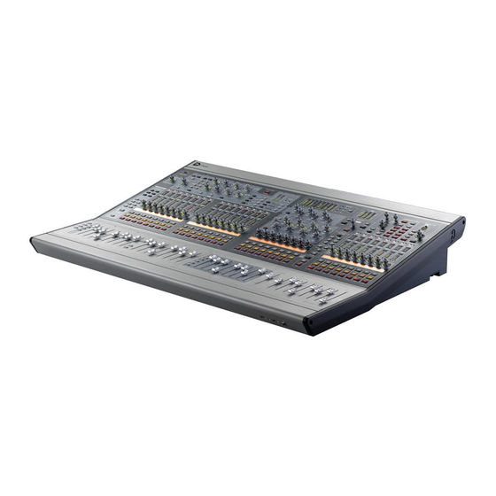
Figure 7. D-Show Profile control surface D-Show Profile provides 24 bankable input channel strips in Input Channel sections, the Assignable Channel Section (ACS), eight bankable output channel strips plus a Mains fader in the Output Masters section, as well as global controls and comprehensive me- tering. -
Page 36: Input Channels And Faders
Input Channels and Faders Input sections provide 24 faders and other controls for Input Channel and FX Returns. Input channels are arranged in two sec- tions: Input channel strips 1–16 are to the left of the Output Master Section, while Input strips 17–24 are to the right. Additional channels are banked to the 24 faders using the Bank A, B, C and D switches. - Page 37 Solo Safe Mode If the Safe LED is flashing, the channel will Input Channel Metering not respond to solo commands (it will not be muted if an- Each Input Channel provides a gain reduction meter, input other channel’s solo button is pressed). If the LED is off, that level meter, and LEDs to indicate EQ, Gate, and stereo status.
- Page 38 Input Encoders and Assignment Controls Pan assigns the encoders to control channel Pan if the chan- Each input channel features one assignable input encoder nel is mono, or stereo channel balance if a stereo. The indica- that can be assigned to control a variety of channel functions tor LED lights when the pan is at center.
- Page 39 Flip to Faders Source Switch When enabled, the current encoder parameter is mapped to The Source switch in the Display section changes the Channel the channel faders. It can still be controlled from the encoder Name display to show the source input which is feeding each row, so the channel fader mirrors the setting.
-
Page 40: Assignable Channel Section
Graphic EQ Banks bands of graphic EQ to the faders. Graphic Assignable Channel Section EQs can be used on D-Show outputs only. For more informa- tion, see Chapter 17, “EQ.” The Assignable Channel Section provides dedicated routing, EQ, Dynamics, and insert controls for the currently selected FX Returns channel. - Page 41 The 6-character Selected Channel display shows the name of Aux Sends the currently selected channel. The Selected Channel display The Aux Sends section provides in/out and level control to temporarily reverts to a parameter display mode any time an route the currently selected channel to any available mono or encoder is adjusted on the selected channel.
-
Page 42: Output Masters
Output Masters The Output Masters section includes eight bankable output channel strips, each with a fader, encoder and channel switches. The Mains fader provides master level control over the Mains (house) output. Output Encoders and switches LCD Display Insert mode Multi-Assign/Show VCA Members Select Select Mains... -
Page 43: Master And Global Controls
Console Mode Master and Global Controls The Config Mode switch toggles the system between Config Global and master controls are located in sections with a dark and Show modes. background, and include the Snapshot, View Modes, Console Config, Mute Groups/Function, Monitoring and Talk- back/Osc sections in the upper right quadrant of the control surface. -
Page 44: Meters
Function Switches Meters In Function mode, this section provides eight Main Function The Meter section includes the following: switches. The default assignments for the first four Function switches include Preview mode on/off (F1), Variable Groups (F2), Copy (F3) and Paste (F4). Function switches can be assigned to perform any number of actions using the Events window. -
Page 45: Chapter 4. Basic Commands And Modes
Chapter 4: Basic Commands and Modes Tool Tips Control Overview With the mouse or a trackball, place the cursor over a screen Most D-Show features and controls that are used during a per- item to display a brief explanation of that item in the banner formance are available from both the control surface and display. -
Page 46: Config Mode And Show Mode
Config Mode and Show Mode Global Modifier Switches D-Show has two main operating modes, Config Mode and D-Show provides a set of global modifier switches, located to Show Mode. Use Config mode to set up your system and op- the left of the input faders: Multi-Select (Shift), Default (Alt), tions;... -
Page 47: Software Screen Pages And Tabs
To reset Threshold on-screen: Software Screen Pages and Tabs Select an input or output channel on-screen. Do one of the following: Viewing Pages • Right-click the Threshold encoder on-screen and choose Reset. To view a page, do one of the following: –... - Page 48 Overview of Software Pages Filing Load, save, and transfer shows and presets. The software screen provides the following pages and tabs. Inputs Select, name, configure, and adjust parameters for input chan- nels and FX Returns. Filing (Load tab) See Chapter 20, “Shows and File Management.” Snapshots Inputs page (analog input shown) Store and recall snapshots.
- Page 49 Patchbay Options Route and name physical inputs and outputs to control sur- Configure system, routing and metering options, set interac- face channels. tion, hardware and general preferences, install plug-ins, and access the Events window. Patchbay (Outputs tab) Options page (System tab) See Chapter 12, “Patchbay.”...
- Page 50 D-Show Profile Guide...
-
Page 51: Chapter 5. Navigating And Selecting Channels
■ Input Channel Banking 9–16). D-Show Profile input fader banking is global across all input The corresponding FX Returns are banked to the input faders. faders. Bank switch A, B, C or D flashes in order to indicate the cur- rent bank assignment of other input faders. -
Page 52: Banking The Output Section
Multi-Select (Shift) Banking the Output Section Multi-Select lets you select multiple channels in order to apply Outputs can be targeted and banked to the Output faders and an action to them in one step. Encoders. These can target Auxes, Groups (or Variable Groups), Matrix mixer outputs, PQ mixer outputs, or VCAs. -
Page 53: Targeting Plug-In Inserts
Multi-Assign Type Text Search The Multi-Assign switch in the Output Masters section is used Type Text search lets you use the keyboard for fast navigation to route multiple channels to the selected output bus. to a channel, or to quickly go to a specific snapshot or event. You can enter the first characters of a channel name or the ab- solute channel number to target that channel on the ACS. -
Page 54: Screen Controls And Shortcuts
Adjusting On-Screen Encoders Screen Controls and Shortcuts You can adjust on-screen rotary encoders by dragging directly over the on-screen knob. Adjusting On-Screen Faders To adjust an on-screen rotary encoder: You can move on-screen faders independently or in ganged fashion. Click on the knob so that it is highlighted. Drag up to turn the encoder clockwise;... - Page 55 Right-click on the lower fader strip on-screen, or on any Reset Fader non-control area of the destination channel, and choose Paste Resets the fader position to zero. to Selected Strip(s). The status displays shows a message con- firming the Paste operation. Reset Resets every parameter on the selected channel(s) to default settings.
-
Page 56: Input Channel Presets
Output Channels The following Output channel parameters Channel Control Shortcuts are not copied or pasted (the current settings of the destina- The on-screen channel faders and encoders provide the fol- tion channels are retained): lowing right-click shortcuts to reset individual parameters and •... - Page 57 To store a channel as an Input Channel Preset: Channel Compatibility and Input Channel Presets Configure an Input Channel as desired. The following describe how different types of channel data is handled when storing or loading Input Channel Presets. Click the Channel Presets icon (the folder icon located to the right of the Channel Routing indicator and +/–...
- Page 58 D-Show Profile Guide...
-
Page 59: Chapter 6. Options
Chapter 6: Options Overview of Options System (System Configuration) The Options page provides the following tabs: • System (see “System” on page 49) The System page lets you allocate DSP resources used for rout- • Busses (see “Busses” on page 52) ing and processing, configure the Main and Aux/Group bus- •... - Page 60 To change a System Config option: Channels Put D-Show in Config mode. Choose the total number of Input Channels you need. This number represents mono channels; each stereo channel uses Go to the Options page and click the System Config tab. two mono channels.
-
Page 61: Devices
Input Settings Bus Configuration Settings With the HDx TDM Record/Playback Option, you can replace The Bus Configuration Settings let you choose the D-Show Stage Rack inputs with fixed HDx card inputs from Aux and Group busses configuration. See “Configuring Aux, Pro Tools|HD. -
Page 62: Other D-Show Options
D-Show system of any size, and utiliz- • To link two mono Aux busses or Variable Group busses ing either D-Show Profile or D-Show Main and Sidecar units, into a bus pair, select the Link option for the correspond- for purposes of preparing shows. - Page 63 Monitor Bus Delay Sets a delay for the signal feeding the FOH Pickoffs Monitor outputs and headphones, for time-aligning near-field The Pickoffs page lets you control the bus pickoff point on in- monitors and headphones to the house system. put strips, as well as specify source and insert points for output busses.
- Page 64 Snapshots Send on Channel This option sets snapshots to send Snapshot General Preferences Bank Select and Program Change commands on a selected The following settings are available in the Snapshots page. MIDI channel. This provides a quick and easy way to send a MIDI command every time a snapshot is fired, without having See Chapter 21, “Snapshots.”...
- Page 65 To show time of day in the Status area: Interaction Go to the Options > Misc page. The Interaction page lets you configure the Assignable Chan- nel Selection, Input Safe Switches, Lights, Meter, and LCD Dis- In the System Clock section, enable the Show Time in Status play options.
- Page 66 Default is 2 seconds for both Clip and Peak hold. These options let you link or unlink faders and encoders across Main and Sidecar units. On D-Show Profile systems, Input Safe Switches these options are unavailable.
-
Page 67: Part Iii Signal Routing
Part III: Signal Routing... -
Page 69: Chapter 7. Inputs And Input Routing
Chapter 7: Inputs and Input Routing Choose the number of Input Channels from the Channels Configuring Inputs pop-up menu. Types of Inputs Two types of inputs are available: Input Channels and FX Re- turns. Input Channels Input Channels are used to control inputs from the Stage Rack, FOH Rack, or Pro Tools playback options. -
Page 70: Assigning Inputs To Channels
Combining Input Channels (Make Stereo) To split stereo channels and make them mono: Put D-Show into Config mode. Pairs of mono Input Channels can be combined to make ste- reo channels, whose left and right sides are then controlled by Select the stereo channel you want to split into mono chan- one input channel strip. -
Page 71: Routing Channels To Busses
Assigning Inputs from the Patchbay Routing Channels To Busses Inputs from the Stage Rack, FOH Rack and any Pro Tools play- Input Channels and FX Returns can be routed to the Mains, back options are routed to Input Channels or FX Returns from Groups and Auxes. - Page 72 Configuring Mains and Groups Busses Routing Channels to Variable Groups The Main busses can be configured to operate as L–R plus To access Variable Group sends 1–8: Mono (Left–Right stereo plus a Mono channel), or as L–C–R Make sure the system is configured for Variable Groups (Left–Center–Right).
-
Page 73: Routing Inputs To Direct Outputs
To adjust the Compressor/Limiter threshold from a channel: Routing Inputs to Direct Outputs In the Encoder Assignment section, press the Comp Thrsh switch. All Input Channels and FX Returns have Direct Output capa- bility. Direct Outputs from Input and FX Return channels can Turn the assigned rotary encoder to set the Compres- be routed to hardware outputs and used as inputs to bus-fed sor/Limiter threshold value. -
Page 74: Using Inserts On Channels
• Click one of the four Plug-In Insert buttons to go to the To use the built-in EQ on a channel, do one of the following: Plug-In Rack, and route the signal to the plug-in using Target the channel by pressing its Select switch. Plug-In Rack controls. -
Page 75: Using Input Direct
Setting the Hardware Insert Location Using Input Direct You can choose the location of the hardware insert in the sig- Input Direct mode lets you completely bypass the built-in dy- nal path, relative to the four plug-in inserts, for each channel. namics and EQ processing, and all inserts on Input Channels A hardware insert does not need to be currently assigned to do and FX Returns. - Page 76 Setting Input Gain Setting Right Offset on Stereo Channels Gain can be controlled from individual channel strips or from On stereo Input Channels and FX Returns, the Gain control the ACS section. affects both the left and right channels. The Right Offset fea- ture lets you offset the gain of the right channel relative to the left channel by –20 dB to +20 dB, within the overall gain lim- its.
- Page 77 High-Pass Filter 20 dB Pad A built-in 4th-order High-Pass Filter can be engaged on each A 20 dB pad can be applied to any analog Stage Rack input as- Input Channel. The HPF corner frequency range is from 20 Hz signed to an Input Channel or FX Return.
- Page 78 Digital Input Sources Channel Mute On systems that include a DSI (Digital Stage Input) card, the Channels can be muted in three ways: explicitly with the following additional settings and displays are provided. channel mute switch; implicitly as a result of another channel being soloed, and as a member of a Mute Group or VCA.
-
Page 79: Chapter 8. Outputs And Output Routing
Chapter 8: Outputs and Output Routing Variable Groups Configuring Outputs When D-Show is in Variable Groups mode, the 8 Group busses operate in much the same way as Aux busses. This bus config- Types of Outputs uration mode lets you send independently controllable sig- nals to all 24 busses in the system. - Page 80 Configuring the Main Busses Select a bus configuration. The Main busses can be configured to operate in the following ways: L–R Plus Mono Pans signals between the left and right chan- nels to the L–R bus, and sums signals to a separate mono bus. L–C–R Pans signals across left, center and right channels.
-
Page 81: Routing Busses To Hardware Outputs
The Patchbay Outputs page shows the name of the bus or Naming Channels mixer and its destination. The destination is also displayed be- Output channel names can be changed from the Outputs page low the channel name in the Outputs page and Patchbay Out- or from the Patchbay. -
Page 82: Using Inserts On Output Busses
In the ACS Bus Assigns section, press the L–R (left and right) In the Inserts section of the Outputs page, do one of the fol- or C/Mono (center/mono) switch so that it is lit. lowing: • Click one of the four Plug-In Insert pop-up menus and choose a plug-in directly from one of the Plug-In Rack Left–Right Center/Mono... -
Page 83: Inserting The Built-In Graphic Eq On Output Busses
Setting the Hardware Insert Location Inserting the Built-In Graphic EQ on You can choose the location of the hardware insert in the sig- Output Busses nal path, relative to the four plug-in inserts, for each channel. A built-in 31-band Graphic EQ can be inserted on any of the A hardware insert does not need to be currently assigned to do following Output bus types: Mains, Groups (or Variable this. -
Page 84: Adjusting Output Controls
To invert the polarity of an output bus: Adjusting Output Controls Target the bus by pressing its Select switch. Different types of outputs can be controlled from the Output Press the polarity inversion (Ø) switch in the ACS Input sec- faders, encoders and switches. -
Page 85: Adjusting Main Bus Controls
Main Bus Mute Adjusting Main Bus Controls The mute status of the Main busses is controlled from the Mute switch located above the Mains Fader. When at least one Main Bus Output Levels of the Main busses is not muted, the Mains mute switch flashes. -
Page 86: Monitoring The Main Mix
Select the pickoff point for the Direct Output by clicking the Monitoring the Main Mix letter to the right of the channel or bus name and choosing from the pop-up menu. You can send the Main mix (the signal present on the Main busses) to the Monitor bus for routing to near-field monitors or headphones. -
Page 87: Matrix Mixers
Matrix Mixers Assigning and Using VCAs Eight Matrix mixers are available for sending up to eight D-Show VCA controls emulate the operation of traditional mono mixes of input channels and busses to any available Voltage Controlled Amplifiers (VCAs). Up to eight VCA faders hardware output or bus-fed plug-in. - Page 88 Using VCAs To adjust the levels of VCA members: Press the VCAs switch to assign control of the VCAs to the Output faders. Move the fader for the VCA whose members you want to ad- just. To solo the members of a VCA: Press the Solo switch on the VCA channels whose members ■...
-
Page 89: Chapter 9. Groups
Chapter 9: Groups The D-Show Output section has 8 available Group busses. Routing Group Outputs to the Main Groups busses can fed by Input Channels and FX Returns. Busses Group outputs can be assigned to the Main Output busses, to available bus-fed plug-ins, and to any hardware outputs on You can route Group outputs to the Main busses on-screen or the system. -
Page 90: Routing Group Busses
In the ACS Bus Assigns section, press the L–R (left and right) Managing Group Bus Assignments or C/Mono (center/mono) switch so that it is lit. Viewing Group Bus Assignments Left–Right Center/Mono Main bus Main bus You can view Group bus assignments from the Input section Assign switch Assign switch of the control surface or from an on-screen list of Group mem-... -
Page 91: Group Bus Signal Flow Options
Resetting Group Bus Assignments Linked Odd/Even Bus Pairs You can remove input assignments from a Group bus To use linked mono Group bus pairs: on-screen. Make sure the Group busses are configured as mono busses. See “Configuring Aux, Group, and Variable Group Busses” on To remove an input assignment from a Group bus: page 70. -
Page 92: Adjusting Group Bus Output Controls
Adjusting Group Bus Output Controls Simple and Expert Operational Modes When configuring Group busses, you can choose between two Group Bus Output Levels operational modes that provide different levels of flexibility: Simple mode and Expert mode. See “Adjusting Output Controls” on page 74. Setting the Operational Mode Group Bus Output Pan Group bus output pan is controlled from the Output encod-... - Page 93 Working with Stereo Group Busses When configured as stereo busses, Groups can operate in the following modes: Simple Mode In Simple Mode, all 8 Group busses function only as true ste- reo busses. Expert Mode In Expert Mode, any of the 8 stereo Group busses can be set to act as true stereo or as dual mono busses, on a per channel ba- sis.
- Page 94 D-Show Profile Guide...
-
Page 95: Chapter 10. Auxes And Variable Groups
Chapter 10: Auxes and Variable Groups The D-Show Output section has up to 16 available Aux busses, Displaying Variable Group Controls and when set to Variable Groups mode, the 8 Group busses are When D-Show is in Variable Group mode, Variable Group replaced by Variable Group busses. - Page 96 Click Edit. To display Variable Group controls from the control surface: Target an Input Channel or FX Return by pressing its Select Click the checkboxes above any of the bus pairs to link or switch. unlink each pair. Do one of the following: •...
-
Page 97: Assigning Inputs To Aux Busses And Variable Group Busses
Pre-Fader This pickoff point is post-HPF, post-EQ Dynamics, Assigning Inputs to Aux Busses and and Channel Inserts, post-Mute, and pre-Fader. The Aux or Variable Group Busses Variable Group Send is affected by the channel mute. You can send signals from any Input Channel or FX Return to To set the Pre pickoff point for an Aux or Variable Group Send: any number of Aux busses or Variable Groups simultaneously. -
Page 98: Routing Aux And Variable Group Busses To Outputs And Plug-Ins
In the Input Encoder Assignment section, press a Send On each of the channels you want to send to the designated switch to assign control of the designated bus to the rotary en- bus pair, press the rotary encoder knob so that its “On” indi- coders. -
Page 99: Adjusting Aux And Variable Group Output Controls
Using Flip to Faders to Access Send Level and Pan Adjusting Aux and Variable Group Simultaneously Output Controls You can use Flip to Faders mode to spill Aux or Variable Group level control to the input faders while retaining control of Controlling Aux Send and Variable Group Send Pan Send pan from the input encoders. -
Page 100: Managing Aux Bus And Variable Group Bus Assignments
To remove all input assignments from an Aux bus or Variable Managing Aux Bus and Variable Group Group bus: Bus Assignments Target the Aux bus or Variable Group bus output channel you want to change by selecting its on-screen channel strip. Variable Group channels are labeled “Groups”... - Page 101 Copying Mains Assignments to Aux Busses and Variable Group Busses You can copy the current Main bus assignments to Aux busses and Variable Group busses, which lets you base monitor mixes from a main mix. Assignments to the Main Left/ Right busses can be copied to linked Aux or Variable Group busses, and assignments to the Center/Mono bus can be copied to mono Aux or Variable Group busses.
- Page 102 D-Show Profile Guide...
-
Page 103: Chapter 11. Matrix Mixers And Pq Mixers
Chapter 11: Matrix Mixers and PQ Mixers The D-Show Outputs section offers 8 mono Matrix mixers and 8 stereo Personal Q (PQ) mixers for setting up alternate mixes, fill and delay tower feeds, and cue, monitor or press mixes. Inputs Matrix mixers and PQ mixers can be configured independently to have different input sources. -
Page 104: Personal Q Mixers
Personal Q Mixers Each of the 8 available Personal Q (“PQ”) mixers can receive up to 12 channels of input. Input sources can be any combination of Auxes, Groups or Mains busses, or any of the eight available PQ User Sends. Each Personal Q mixer has a stereo output. PQ Source controls PQ output level and... - Page 105 Configuring User Inputs Assigning Input Sources You can assign up to eight User Inputs to be available globally To assign input sources to a Matrix or PQ mixer: to the Matrix mixers and, separately, up to eight User Inputs Go to the Outputs page and click to select a Matrix or PQ to be available globally to the PQ mixers.
-
Page 106: Adjusting Matrix Mixer And Pq Mixer Input Controls
PQ mixer are controlled by the Output Encoders. Press the Personal Qs switch in the Output fader assign sec- The eight Output Encoders on D-Show Profile control the in- tion. put levels of the currently selected Matrix mixer or PQ mixer input sources. - Page 107 To link or unlink inputs to Matrix or PQ mixers: Resetting Matrix Mixer and PQ Mixer Input Controls Go to the Outputs page, and click to display the Matrix or PQ mixer. You can reset level, pan and stereo link settings for any matrix or PQ mixer.
-
Page 108: Adjusting Matrix Mixer And Pq Mixer Output Controls
Matrix and PQ Output busses provide standard Output chan- nel controls (Polarity, Solo and Mute), Direct Outs, inserts and D-Show Profile does not provide a PQ mixer output balance built-in Graphic EQ capabilities. control. Use the on-screen Balance encoder in the Outputs page of all PQ mixers instead. -
Page 109: Working With A Pq Controller
Working with a PQ Controller Snapshot Data and Parameters for Matrix and PQ Mixers When an optional Personal Q remote control system is con- nected to D-Show, it can be used to adjust the controls in the Snapshots can store and recall all source assignments (of each Personal Q mixers from a remote location. - Page 110 D-Show Profile Guide...
-
Page 111: Chapter 12. Patchbay
Chapter 12: Patchbay The main tools and sections of the Patchbay screen are the fol- Accessing the Patchbay lowing: To show the Patchbay screen: Tabs Press the Patchbay switch, located in the View Modes sec- ■ The Patchbay is navigated using the following tabs. tion, or click the Patchbay page name on-screen. - Page 112 Patching Grid Visual Indicators and Displays The Patching Grid shows hardware I/O across the top, and The Patchbay uses the following visual display conventions in D-Show channels down the left side for the currently selected all its pages and tabs. I/O and Channel type.
-
Page 113: Navigating The Patchbay
Text Display of Patch Source and Destination To search for and select a channel: Type the first few letters, full name, or channel number of Above the grid tabs, there are “from” and “to” text display the channel. For example, type “s” to go to the first channel fields that display the full text names of hardware I/O and beginning with the letter s (such as Snare). -
Page 114: Routing Channels In The Patchbay
Scrolling in the Patchbay Routing Channels in the Patchbay To scroll through the channel list (vertically): To route channels in the Patchbay: Move the cursor over a channel name at the left of the Go to a patchbay page by clicking the appropriate I/O tab, Patching Grid. - Page 115 Using the Arrow Keys to Route Channels To route a D-Show Output bus to multiple hardware outputs: Go the appropriate Output display in the Patchbay. You can also use the Arrow keys instead of the trackball to as- sign routing. Click in the Patching Grid to route the Output bus to the first hardware output.
-
Page 116: Warning When Stealing Inputs Or Outputs In The Patchbay
Inserts and Routing in the Patchbay To cancel a reassignment: Click Cancel to cancel the reassignment and leave the ■ Hardware inserts are available on all D-Show channels to in- patchpoint unchanged. corporate external hardware processing. D-Show inserts can only be routed to and from the FOH Rack. –... -
Page 117: Chapter 13. Metering
Chapter 13: Metering D-Show provides signal metering on the control surface chan- Compressor/Limiter Gain Reduction Meter nels and meter bridge, and on-screen. The LEDs in the Compressor/Limiter meter show the amount of gain reduction being applied to the input channel by the built-in Compressor/limiter from right to left, according to Channel Meters the following scale:... -
Page 118: Acs Input And Dynamics Meters
Bank Clip Indicators Selected Channel Gain Reduction Meters The Clip LED at the top of Input Channel and FX Return The three dynamics gain reduction meters in the ACS section channels lights when clipping occurs on a hidden fader bank. show gain reduction for the built-in Compressor/Limiter, the The channel position of the Clip indication corresponds to built-in Expander/Gate, and any applicable Dynamics plug-in... -
Page 119: Meter Bridge
The 10 bi-color LEDs show input levels from bottom to top, Meter Bridge according to the scale shown in Table 14 on page 109. The D-Show Profile meter bridge includes Bus and Main Out- Selecting Output Meter Display puts meters. -
Page 120: Metering Options
Peak Mode Meters follow the characteristics of a standard Multiple Channels peak meter. In this mode, the meter response is instanta- In PFL or AFL mode, when multiple channels are soloed, the neous, showing the true peak level of the metered signal. left and right channels of the Solo bus are metered on the Se- lected Channel meters, pre-Solo Trim control. -
Page 121: Chapter 14. Solo And Monitor Busses
Chapter 14: Solo and Monitor Busses Solo In Place (SIP) Solo Bus Modes SIP Solo mode applies to Input Channels and FX Returns only. D-Show offers three modes for soloing channels in the system: Solo In Place sends the signal from the soloed channel to the Pre-Fader Listen (PFL), After-Fader Listen (AFL) and Solo In Main busses. -
Page 122: Solo Operation Options
To select the Solo mode on-screen: Auxes/Variable Groups Follow AFL Go to the Options page and click the Busses tab. The “Auxes/Variable Groups Follow AFL” option is especially useful for monitor mixing, because it provides instant access Under Solo and Monitor Operations, select the Solo mode. to any mix by the soloing the mix output (in AFL mode). -
Page 123: Solo Bus Operation
Auto Cancel and Input Priority Soloing Single Channels The Auto Cancel option determines whether Solo switches To solo a single channel, do one of the following: cancel other soloed channels or are additive (latching). The Press the channel’s solo switch so it is lit. The solo switch ■... -
Page 124: Solo Safing Channels
Clearing Solos To toggle the solo safe status of a channel, do one of the following: If any channel is soloed on the console, the Solo Clear switch Select one or more channels, then press the Safe switch in ■ in the Solo/PFL section flashes. - Page 125 Click the Plug-In Input selector at the top of the correspond- 2-Track Return ing rack slot, and choose Bus Outs > Mains > Monitor - stereo. If 2-Track input is enabled, any signal from those inputs is sent to the Monitor bus. If Mix to Monitors is enabled, the 2-Track input overrides it so you can monitor the 2-Track re- turn without having to disable Mix to Monitors.
-
Page 126: Talkback, 2-Track And Oscillator Controls
Adjusting Monitoring Level Routing Talkback Microphone Input Output levels for the near-field monitors and the headphones To route Talkback microphone input to any D-Show Input Channel are controlled by the corresponding volume knobs in the or FX Return: Monitoring section. Go to the Patchbay and click the Inputs tab. - Page 127 Activating Talkback Input and Setting Level To set the Talkback Dim Level: Go to the Options page and click the Misc tab. To activate and set the level for Talkback input: In the Talkback section, double-click the Dim Level text box Press the Talkback switch in the Talkback/Osc section so and enter a Dim Level value in the range –60 dB (maximum that it is lit.
- Page 128 Activating Intercom Input To route the 2-Track inputs to any D-Show output bus: Go to the Options page and click the Misc tab. To activate the Com input so it is mixed with the Monitor bus: In the 2-Track section, select “Analog 2-Track” or “Digital Route the Intercom input as described in the previous sec- 2-Track”...
- Page 129 Activating 2-Track Input and Setting Level To route any D-Show Direct Output to the 2-Track outputs: Go to the Patchbay and click the Directs tab. To activate and set the general level for 2-Track Input: To the left of the channel grid, click the tab for a channel Press the 2-Track switch in the Talkback/Osc section so that source (Channels, FX Returns, or Outputs).
- Page 130 Routing Oscillator Output Activating the Oscillator and Setting Level The output of the D-Show internal oscillator can be routed to To activate and set the level for the oscillator: any of the output busses. Press the Oscillator switch in the Talkback/Osc section so Signals are routed to output busses post-mute and post that it is lit.
-
Page 131: Chapter 15. Muting And Mute Groups
Chapter 15: Muting and Mute Groups Muting Output Busses Muting Mute operation is post-fader on all types of Output busses. Channels can be muted in three ways: explicitly (lit solid), with the channel mute switch; implicitly (flashing), as a result To control the mute status of an output bus: of another channel being soloed, and as a member of a Mute Press one of the following switches in the Output assign-... -
Page 132: Mute Groups
Do one of the following: Mute Groups • To confirm the Mute Group definition, press the flashing Assign switch or the flashing Mute Group switch (1–8). D-Show lets you assign channels to any of 8 available Mute Groups. Mute Groups let you mute and unmute multiple –... -
Page 133: Function Switches
Disabling Mute Groups Function Switches You can temporarily disable all Mute Group functions. When D-Show Profile provides 8 Function switches (F keys). Mute Groups are disabled, all channels implicitly muted as a result of Mute Group activation are unmuted. Channels can still be explicitly muted when Mute Groups are disabled. - Page 134 D-Show Profile Guide...
-
Page 135: Part Iv Processing
Part IV: Processing... -
Page 137: Chapter 16. Dynamics
Chapter 16: Dynamics D-Show provides the following dynamics features: Built-In Compressor/Limiter • A built-in Compressor/Limiter and Expander/Gate is avail- able on each Input Channel. One built-in Compressor/Limiter is available on each Input Channel. The Compressor/Limiter defaults to compression, or • Dynamics plug-ins can be used on input and output chan- can be switched to a limiter by setting the Ratio to its maxi- nels. -
Page 138: Built-In Expander/Gate
In/Out Takes the built-in Compressor/Limiter in or out of cir- Built-In Expander/Gate cuit (bypass). The Compressor/Limiter can be taken in or out of circuit using the ACS Comp/Lim In switch, by clicking the One built-in Expander/Gate is available on each Input Chan- input encoder when Comp Thrs is enabled, or by clicking the nel. -
Page 139: Channel Modes Affecting Dynamics
Side-Chain Keying The Expander/Gate supports side-chain and Channel Modes Affecting Dynamics key listen. For details, see “Side-Chain Keys and Filters” on page 132. The following features affect operation of built-in Dynamics. Expander/Gate Gain Reduction Meters Dyn Pre EQ A single bi-color Gate LED on each input channel indicates By default, built-in Dynamics processing occurs before Exp/Gate activity, as shown in the following table. - Page 140 ACS Dynamics Section Software Screen Dynamics Controls The Dynamics controls in the ACS provide a unified, consis- The software screen lets you adjust built-in or plug-in dynam- tent set of controls for both built-in and plug-in dynamics ics on-screen, with simultaneous access to Comp/Lim and processing for the targeted channel.
-
Page 141: Dynamics Settings And Presets
Using the Dynamics Graph Display To adjust a Dynamics plug-in from the control surface: Target the channel with the plug-in by pressing the channel In addition to the on-screen encoders and buttons, you can Select switch. adjust Dynamics parameters using the Dynamics Graph. Press the plug-in Select switch (located next to the ACS gain To adjust Dynamics parameters on-screen using the Graph reduction meters in the Dynamics section). -
Page 142: Side-Chain Keys And Filters
Presets for Built-In Dynamics Side-Chain Keys and Filters D-Show lets you store and load dynamics settings as presets The built-in Compressor/Limiter and Expander/Gate support for built-in and plug-in dynamics processors. Presets can be side-chain triggering. accessed from the control surface or on-screen. To save or load a preset: Key In/Out Adjust EQ settings on a channel (if saving a preset), or select... - Page 143 Click the Key Source selector and choose an available chan- Side-Chain Filters nel or bus. Both the Compressor/Limiter and the Expander/Gate side-chains provide two bands of EQ to band-limit the range of frequencies in the key signal. To enable a side-chain EQ on-screen: Click the LPF or HPF encoder.
- Page 144 D-Show Profile Guide...
-
Page 145: Chapter 17. Eq
Chapter 17: EQ D-Show provides the following EQ features: Hardware Inserts • A built-in EQ is available on each Input Channel and FX D-Show lets you insert a hardware EQ processor and control Return. its in/out state and insert position on-screen. •... -
Page 146: Channel Modes Affecting Eq
Band In/Out Each of the available EQ bands can be taken in or Analog and Digital EQ Modes out (bypassed) using the band In/Out control. In the ACS EQ The Analog/Digital button toggles the built-in parametric EQ section, the Gain knob for each band serves as the in/out con- between digital mode and analog mode, on a per-channel ba- trol by pushing the encoder. -
Page 147: Adjusting Eq
ACS EQ Controls Adjusting EQ The EQ controls in the ACS provide a unified, consistent set of D-Show provides EQ controls in input fader strips, the ACS, controls for both built-in and plug-in EQ processing for the and on-screen. targeted channel. Twelve dual-purpose rotary/switch encod- ers control EQ parameters and their settings. - Page 148 To adjust EQ parameters from the ACS: Software Screen EQ Controls Target a channel by pressing its Select switch. You can adjust the built-in EQ using dedicated on-screen but- tons for band in/out and bell/shelf toggling. Press the EQ In switch to enable built-in EQ on that chan- nel.
-
Page 149: Graphic Eq For Outputs
Choose the number of Graphic EQs from the pop-up menu. Using the EQ Graph Display You can choose to have 0, 8, 16, or 24 Graphic EQs. The on-screen EQ graph lets you use the trackball to adjust fre- quency and gain for any available EQ band. graph Dragging handles in the EQ graph display Configuring the number of Graphic EQs... -
Page 150: Adjusting Eq Plug-Ins
Graphic EQ Controls Adjusting EQ Plug-Ins The Input Faders provide control of Graphic EQ frequency D-Show compatible EQ plug-ins can map their gain, fre- bands. You can also use on-screen controls to adjust graphic quency, and Q/bandwidth controls to corresponding encod- EQ parameters. - Page 151 Go to the channel where you want to paste the settings. Do any of the following: • To preview an existing preset, click its name in the Pre- Do one of the following: sets window. • To paste a parametric EQ setting, right-click in the new •...
- Page 152 Control Ranges for Built-In Parametric EQ (All Modes) Table 18. Control ranges for built-in parametric EQ Band Control Range (Digital) Defaults (Digital) Range (Analog) Defaults (Analog) High Frequency 20 Hz to 20 kHz 10 kHz 2 kHz to 20 kHz 6 kHz (Bell/Shelf) Gain...
-
Page 153: Chapter 18. Hardware Inserts
Chapter 18: Hardware Inserts D-Show lets you route signal to and from external devices as hardware inserts. Hardware inserts may be used on Input Channels, FX Returns, Groups, Auxes, Matrixes, Personal Qs, and the Main busses. Up to 16 analog and 8 digital hardware inserts may be used at one time, depending on the I/O configuration of the FOH Rack. Connecting External Effects Units Outboard gear is made available to the system by connecting its inputs and outputs to connectors on the FOH Rack. -
Page 154: Assigning Hardware Inserts To Channels
The Patchbay Inserts page shows the name of the channel and Assigning Hardware Inserts to its destination at the current cursor location. The Insert loca- Channels tion is also displayed in the Inserts section in the Inputs or Outputs page. You can assign hardware inserts directly from the Inputs page or Outputs page. -
Page 155: Chapter 19. Plug-Ins
Config mode is required to install plug-ins, assign them to For complete information on D-Show compatible plug-ins, rack slots, and to establish side-chain routing. When in Show visit the Digidesign website (www.digidesign.com). mode, any operations that might interrupt audio throughput are locked out and unavailable. - Page 156 Available plug-ins Installed plug-ins Install Device selector Figure 11. Options > Plug-Ins screen Click the Device Selector pop-up menu and do one of the Removing Plug-Ins following: Uninstalling a plug-in removes the plug-in from the racks but • Choose Previous Installs to access any plug-in installers the installer remains in the Previous Installs cache, making it after a system update.
- Page 157 This is required the first time you install Usage Guide on the Standalone Software CD or at the the plug-in, and whenever you need to re-install a plug-in Digidesign website (www.digidesign.com). (such as after using the D-Show System Restore CD to update or reset the system).
-
Page 158: Overview Of Plug-Ins
USB Ports for iLoks Overview of Plug-Ins D-Show Profile provides three USB ports on the control sur- The Plug-Ins screen displays the plug-in Racks, where the ma- face and three on the FOH Rack, any of which can be used to jority of plug-in set up features are located. -
Page 159: Plug-In Racks
Plug-In Racks The Plug-Ins page provides four plug-in racks. Each of the four racks has 25 slots into which you can load a plug-in. The four dif- ferent racks can be viewed all at once, individually, and in varying zoom levels. Click to display Racks 1–4 Mini-view... - Page 160 Zoom View (Plug-In View Mode) Identifying Rack Slots In Zoom view, a single rack remains on-screen to the left, and The racks indicate which plug-in is currently targeted by high- the rest of the screen displays the targeted plug-in. lighting its rack slot controls in blue. Targeted plug-in (rack slot highlighted in...
-
Page 161: Rack Slots
Unavailable Plug-Ins Rack Slots When a plug-in cannot be used because of insufficient DSP re- Each rack provides 25 plug-in slots. You can assign any in- sources, because it is disabled, or because it is not installed on stalled plug-in to any available rack slot. the system, a warning icon is shown in front of the affected plug-in. -
Page 162: Assigning And Routing Plug-Ins
Channel Insert or Bus Output Assigning and Routing Plug-Ins The Channel Insert/Bus Output pop-up menu displays differ- Before a plug-in can be used to process audio, it must be as- ent choices depending on whether the plug-in is being used as signed to a rack slot. - Page 163 Moving and Copying Plug-Ins Routing Plug-Ins (Config Mode Only) After a plug-in has been assigned to a rack slot, you can specify its routing. Plug-In routing determines whether the plug-in is To move or copy a plug-in in the rack, drag the plug-in icon to used as a channel insert or as a bus processor.
- Page 164 To insert a plug-in on a channel from the Plug-Ins page: To use a plug-in as a bus processor: Make sure the plug-in is already assigned to a rack slot. (For Go to the Plug-Ins screen. more information, see “Assigning and Routing Plug-Ins” on Make sure the plug-in is installed and assigned to a rack slot.
-
Page 165: Adjusting Plug-Ins
Plug-In the Source Pickoff pop-up menu. Adjusting Plug-Ins Plug-Ins can be adjusted from the console or on-screen. D-Show Profile provides plug-in controls in the ACS and Out- put encoder sections for real-time interaction with plug-ins. Control Surface In/Out ACS EQ controls... - Page 166 Some delay plug-ins include automatic beat clock and tempo controls (such as the Tempo Sync feature in the Digidesign Mod Delay plug-in). These types of plug-in con- Unassigned trols default to On, or active. Be sure to manually deacti- vate Tempo Sync or the equivalent in these plug-ins.
-
Page 167: Adjusting Eq And Dynamics Plug-Ins From The Acs
Software Screen Pinning a Plug-In View The software screen can also be used to patch, route, or It is possible to decouple the plug-in view from the console for re-route plug-ins during a performance, even while in Show consistent and constant access to a single plug-in on-screen, mode. -
Page 168: Plug-In Presets And Snapshots
Five-Band EQs Plug-In Presets and Snapshots When a plug-in has more than four bands, some controls will D-Show lets you save and load plug-in Presets files to import, be unavailable in the ACS EQ section. Use the Output encod- export, and transfer plug-in settings files. ers to access and adjust additional controls. -
Page 169: Plug-In Dsp Usage
• From the control surface, use the Presets and Snapshots Remove this Plug-In in Snapshot Removes reference to this displays and controls to scroll through, select, load, and plug-in in the currently targeted snapshot, or from all cur- save plug-in presets. Scrolling through the list using the rently selected snapshots. -
Page 170: Plug-In Levels
Plug-In Levels Plug-In Latency and Processing Delay D-Show displays its levels in meters in dBVU, with Plug-In latency includes processing delay of the plug-in itself 0 dBVU =+4dBu analog out = –20dBFS. plus routing delay, as follows: • Instance delay: (2 samples per plug-in) Internally, D-Show provides up to 48-bit processing for •... -
Page 171: Part V Shows
Part V: Shows... -
Page 173: Chapter 20. Shows And File Management
Chapter 20: Shows and File Management D-Show lets you store, recall and transfer D-Show system set- Creating Show Folders tings. There are three types of information files that can be managed separately, as follows: To create a new Show Folder: Go to the Filing page and click the Save tab. -
Page 174: Loading Shows
Show Files Renaming Show Files To rename a Show file: Creating and Saving Show Files In the Shows column, click a Show file name to select the When you create a new Show file, it captures the current state file. of the D-Show system. -
Page 175: Working With Presets
D-Show systems. Show files include D-Show system configuration settings (such as the type of D-Show console (D-Show Profile, or a Creating Preset Folders D-Show Main and Sidecars); the number of Mix Engines;... - Page 176 Click the Preset Folder name and choose a Preset Folder Renaming Preset Folders from the pop-up menu. Any Presets in the folder appear in the left column. To rename a Preset Folder: In the left column, click a Preset Folder name to select the folder.
-
Page 177: Transferring Settings, Shows And Presets
Do one of the following to select the items to transfer: Transferring Settings, Shows and • In the left column, select the items you want to transfer Presets from D-Show to the portable storage device. – or – You can copy Console Settings, Shows, and Presets to and from a portable storage device (such as a USB key disk) for •... -
Page 178: Undoing Changes Using The History Feature
To synchronize Settings, Shows, or Presets between D-Show and Undoing Changes Using the History a portable storage device: Feature Go to the Filing page and click the Transfer tab. D-Show automatically saves the current state of the console Connect a portable storage device (such as a USB key disk) to while you are working, allowing you to quickly return the D-Show. - Page 179 Loading an Auto-Saved Show To return the console to an earlier state at any time, you can load any of the auto-saved Show files displayed in the History tab. To load an auto-saved Show file: Go to the Filing page and click the History tab. In the Show Folders column, click the Show Folder name to select the folder and display its contents in the Shows column.
- Page 180 D-Show Profile Guide...
-
Page 181: Chapter 21. Snapshots
Chapter 21: Snapshots The D-Show Snapshots feature lets you flexibly store and recall a wide range of console mixing parameters. Snapshots are com- monly used to store the mixer setup and levels for individual scenes, songs or sound cues in a performance. Snapshots store in- formation about channels and mix parameters, and you can use a variety of methods to edit, preview, and manage snapshot data. - Page 182 Undo Returns the console to its state before the last snapshot To display the Snapshots page, do one of the following: command. Click the Snapshots tab on-screen. ■ New Creates a new snapshot that captures the current state of – or – all data types and channels.
- Page 183 Channel Scope Controls Selected Channel Indication Channels may be included or excluded from snapshots. The The Snapshots page indicates the currently selected channel. Snapshot Channel Faders display the scope status of each If the selected channel is not scoped in the currently se- ◆...
-
Page 184: Snapshot Controls On The D-Show Profile Control Surface
Next Instantly recalls the snapshot immediately following the Next Snapshot Indication in Status Display most recently recalled snapshot. This switch mirrors the Re- The Snapshot Status display shows the currently targeted call Next button in the Snapshots page. (next) snapshot in red text directly above the display of the last (most recently recalled) snapshot. - Page 185 Snapshot Keyboard Shortcuts Snapshot Type Text Search When the Snapshots page is displayed, you can perform the Type Text search lets you use the keyboard for fast navigation following Snapshot functions with these keyboard shortcuts: of the Snapshots List. Snapshot Function Keyboard Shortcut To search for and target a snapshot: Target Next/Previous Snapshot...
-
Page 186: Creating Snapshots
For each parameter of the scoped channels you want af- Creating Snapshots fected when the snapshot is later recalled, click the corre- sponding Data Type button so that it is scoped (displayed in Snapshots can be created at any time to store the current red). -
Page 187: Recalling Snapshots
Recalling Snapshots The Snapshot Recall buttons combine target and recall actions in one step, causing the previous or next snapshot to be instantly active. These buttons cannot be used to Targeting Snapshots preview snapshots before recalling them. Targeting a snapshot lets you preview which data types and Targeting Before Recalling Snapshots channels will be affected by that snapshot before recalling it. -
Page 188: Recall Safe And Channel Automation Safe
Recall Safe and Channel Automation The master On button toggles the entire Recall Safe feature on Safe or off globally. When lit (blue), Recall Safe is active. When dark, Recall Safe is suspended. The Recall Safe tab in the Snapshots page provides global au- tomation safe settings of nearly every section of the console. - Page 189 Some A dark triangle inside a lit blue circle indicates that at Parameter Matrix least one item in that column or row is safe enabled. The parameter matrix is a scrollable grid in which you can safe parameters and channels. You can undo and redo parameter All A lit (white) triangle indicates that all items in that column matrix operations.
- Page 190 To safe individual parameters or channels using the computer MIDI keyboard: To enable Recall Safe for MIDI Snapshot output: Place the cursor above the grid, above a parameter or chan- nel name, or above any Channel Safe button. To be sure the Click the MIDI Snapshot Output Safe button, located above ■...
- Page 191 Using Scope Sets Automation Safing Channels The configuration of the Recall Safe page can be stored as a You can suspend the effect of snapshots on individual chan- Scope Set settings file. Scope Sets can be previewed, recalled nels using any of the following Automation Safe controls: and transferred just like D-Show plug-in, EQ and Dynamics Input Channel Safes Temporarily suspend the effect of snap- settings.
-
Page 192: Managing Snapshots
In the Snapshot list, click the padlock icon at the far right of Managing Snapshots the row for any item. The padlock icon illuminates to indicate the snapshot is now locked. You can manage snapshots in the list by storing, locking, clearing, duplicating, deleting, or moving them. - Page 193 Available Operations with Locked Snapshots Duplicating Snapshots The following table details which operations can or can not be Snapshots can be duplicated from the Snapshots list. You can performed on a locked snapshot. undo Duplicate commands. Summary of allowed/disallowed operations when locked To duplicate snapshots: Operation Allowed...
-
Page 194: Making Changes To Snapshots
Examples of Absolute and Relative Edits Making Changes to Snapshots Absolute Changing a fader level from 0 dB to –3 dB and apply- There may be situations where you need to change specific pa- ing that change results in that fader being set identically to rameters in existing snapshots while leaving other parameters –3 dB in all selected snapshots. -
Page 195: Preview Mode
Using Propagate Mode Preview Mode You can use the Propagate command to capture changes and Preview mode lets you recall, store and edit snapshots without apply them to existing snapshots. Propagate mode is most affecting the current mix. useful when you realize during the course of mixing that you want to capture your current settings to use in other snap- When enabled, Preview mode takes the console offline from shots. - Page 196 Recall and Edit an Existing Snapshot Recall a snapshot to pre- Undo and Preview Mode view its settings and make any adjustments necessary, being In Preview mode, you can Undo actions applied to the Snap- sure to re-store the snapshot before exiting Preview mode. shot List (such as Recall, Store, New and Duplicate) without af- Storing a snapshot in Preview mode does not affect previously fecting the online mix.
- Page 197 Available and Unavailable Functions in Not Available in Preview Mode Preview Mode The only controls not available while in Preview mode are those controls which are not able to be stored or recalled via In order to maintain essential mix indicators and controls snapshots.
-
Page 198: Undoing Snapshot Commands
The following plug-in functions are not available while in Pre- Undoing Snapshot Commands view mode: • Plug-ins cannot be added to or removed from rack slots The Undo function returns the console to the state immedi- • Plug-in presets cannot be recalled or saved ately before the last snapshot command. -
Page 199: Adding Midi Messages To Snapshots
Click Add and choose a message from the pop-up menu. Adding MIDI Messages to Snapshots No MIDI message data is captured when a snapshot is first cre- ated. MIDI messages are added to existing snapshots directly from the MIDI list. You can store up to 20 MIDI messages in each snapshot. -
Page 200: Adding Plug-In Data To Snapshots
It is also possible to select multiple plug-ins in the Snapshots Safing MIDI Message Output Plug-Ins list and remove or update these plug-ins across mul- You can temporarily disable output of embedded MIDI mes- tiple snapshots using Right-click commands. Selections can be sages so that they are not sent when a snapshot is recalled, contiguous or non-contiguous plug-ins in the list. -
Page 201: Snapshot Options
Click the Snapshots menu for the plug-in to be updated and Removing a Plug-In from Snapshots choose Update This Plug-In In Selected Snapshots. To remove a plug-in from snapshots from the Snapshots page: The selected plug-in is updated within the currently targeted Select an individual snapshot, or create a multi-selection of snapshot, as well as all other snapshots within the multi-selec- snapshots in the Snapshots List. - Page 202 Pre Settings Snapshots can be used to recall the preamplifier settings on in- puts for all scoped Input Channels. You can set any of the fol- lowing Pre parameters to be recalled by the Pre data type but- ton: Gain, Pad and Phase/polarity, +48V (Phantom Power), HPF corner frequency and in/out state.
-
Page 203: Snapshot Data Types And Parameters
Snapshot Data Types and Parameters Table 23. Snapshot data types and parameters included in each data type Snapshot Data Type Included Parameters (for Each Scoped Channel Strip) Fader Main volume level Mute Mute state EQ type selection (analog/digital); EQ in-circuit state; 4 bands (2 bands on FX Returns) of gain, freq, Q, bell/shelf selection (digital only), band on/off Compressor/Limiter in-circuit state;... - Page 204 D-Show Profile Guide...
-
Page 205: Chapter 22. Events
(a footswitch input) causing a single action (Recall GPI General Purpose Interface, also commonly known as a Next Snapshot). logic interface. D-Show Profile provides eight GPI inputs, and Events can also be quite complex and involve multiple trig- eight GPI outputs. -
Page 206: The Events Window
The Events Window The Events window is the working area of the Event List system, and is available as a new tab in the Options page (Options > Events). It is comprised of an upper Event List area and a lower status area. Event List Commands Triggers Event List... - Page 207 Triggers Actions The Triggers list shows the name and properties of each trigger The Actions list shows the actions defined in the currently se- defined for the currently selected event, as well as commands lected event, as well as commands to create and manage ac- to create and manage triggers.
-
Page 208: Creating Events
Moving Events Creating Events Selected events can be dragged and dropped to new locations The basic steps to create an event include the following: in the list. You can also manually edit the Event number to re- sequence items. • Add a new event in the Event List (see “Adding an Event” on page 198). - Page 209 Disabling an active event does not automatically de-activate Deleting and Clearing an Event any associated actions configured for While Active behavior. Deleting an event removes it permanently from the Event List. Use the Reset command instead (see “Resetting Events” on Clearing an event leaves the named Event in the Event List but page 203).
-
Page 210: Creating Triggers
A trigger is considered to be “false” (or, not occurring) when- Creating Triggers ever its function and properties are not met, such as when a footswitch is not being pressed, or while a fader remains be- Each event can have up to eight triggers. You create new trig- low its assigned trigger threshold. -
Page 211: Creating Actions
Duplicating Triggers At least one trigger, but not all, must be true. The following ta- To duplicate a trigger: ble shows the effect of XOR on events with multiple triggers. Select one or more items in the Triggers List. In the table, 0 indicates a false trigger condition (not occur- ring) and 1 indicates a true condition (occurring). -
Page 212: Testing Events
Editing an Action Type and Properties Action Wait All actions let you specify a Wait time of up to 100 seconds for To edit an action: the action to wait before firing. This can be useful for synchro- Double-click the action row in the list. Or, right-click the ac- nizing the timing of multiple external devices, or to build tion item and choose Edit. -
Page 213: Resetting Events
Resetting Events Snapshots and Events You can use the Reset features to quickly reset Active or in-Test Events can include snapshot functions among their triggers events to “ready.” You can also use the Reset All command (in and actions. the Events Commands buttons) to immediately reset all Snapshots as Triggers events in the list. -
Page 214: Default Settings, Templates And Examples
Default Settings, Templates and Examples Default Events D-Show 2.5 includes the following pre-defined events for you to use as examples and as the starting point for your own events. Default events Event Number Type and Name Triggers Actions undefined (choose an action) Footswitch 1 Switch 1 (Footswitch 1) Closed Footswitch 2... -
Page 215: Events And Show File Compatibility
Transferring v2.5x Show Files from D-Show Profile to D-Show On or Off each time the footswitch is pressed. GPI I/O is only available on D-Show Profile consoles. When a If you prefer momentary talkback, edit the event by doing the Show file containing Events is loaded on a system using a following. -
Page 216: Trigger Types
Trigger Types The following table lists the available trigger types and properties, along with a description of each. Table 23. Trigger List, with default settings Trigger Type Property 1 Property 2 Description Fader Above Channel name/number Fader level –inf to +12 dB Fader moved above threshold level (Default: –60 dB) Fader Below... -
Page 217: Action Types
Action Types The following table lists the available Action types and properties, along with a description of each. Table 24. Action types Action Type Property State Behavior Description Target Next Channel Selected Channel advances by one Target Previous Channel Selected Channel reverses by one Copy Selected Channel Channel copy operation Paste to Selected Channel(s) - Page 218 Table 24. Action types Action Type Property State Behavior Description GPI Output 1–8 (D-Show Open Pulse, 0.3s Pulses or latches selected GPI Out- Profile only) Closed (default) (default) Toggle Latch While Active Flash Console Lights Flashes console lights Top Row Flip to Faders Latch (default) Mirrors top encoder row Flip to Fad- (D-Show Main only)
-
Page 219: Chapter 23. Synchronization
Chapter 23: Synchronization D-Show provides a set of MIDI-based synchronization features Control MTC playback from the MTC generator controls by that allow automation and remote control of snapshots, and doing any of the following: triggering of external devices when snapshots are recalled. •... - Page 220 Do one of the following: Snapshot MIDI Time Code Display • During playback, click the New button. When D-Show is set to generate or read MIDI Time Code, the – or – Snapshots List shows time code values and a green Recall En- •...
-
Page 221: Remote Control Of Snapshot Recall
Chasing MIDI Time Code Remote Control of Snapshot Recall With snapshots enabled for automated recall, the Chase MTC D-Show can be set to recall snapshots in response to MIDI function needs to be engaged to allow automated recall to oc- control messages sent from an external device such as an AV cur. -
Page 222: Triggering Of External Devices On Snapshot Recall
Triggering of External Devices on Sending MIDI Messages on Snapshot Snapshot Recall Recall D-Show can be set to send MIDI Bank and Program Change You can add up to 20 specific MIDI messages to each snap- messages whenever a snapshot is recalled, to trigger external shot. -
Page 223: Chapter 24. Using The D-Show Standalone Software
D-Show system are visible in the • Download the D-Show Standalone Software Installer Standalone software as offline (unavailable) plug-ins. You can from the Digidesign website (www.digidesign.com). assign offline plug-ins to racks, and assign plug-in rack routing – or –... -
Page 224: Simulating A D-Show Configuration
Launch the Add/Remove Programs Control Panel. • Save data to disk, then transfer it to an external USB storage Choose Digidesign D-Show, then follow the instructions device. on-screen. • Transfer data from the USB device, then load the data. - Page 225 Transfer and Load Data to the Creating and Editing Shows and Presets Standalone Software Use the techniques explained throughout this guide to assign Connect the USB storage device to your laptop. Make sure routing, rename channels, and to configure other parameters. the drive is mounted before proceeding.
-
Page 226: Exporting Patchbay Names To Text
Exporting Patchbay Names to Text With Standalone software, the contents of each Patchbay page can be exported to a text file. This can be useful for gen- erating an input list (line list) directly from the system. For ex- ample, build and customize the Patchbay for an upcoming show, then export and print the channel names list for use during sound check. -
Page 227: Part Vi Specifications
Part VI: Specifications... -
Page 229: Chapter 25. Mechanical Specifications
Chapter 25: Mechanical Specifications D-Show Profile Mechanical Specifications Maximum Height (front) 3.2 inches (81 mm) Maximum Height (rear) 6.8 inches (169 mm) Maximum Width 45.21 inches (1150 mm) Maximum Depth 31.11 inches (790 mm) Weight 90 lbs (40.823313 Kg) Power Requirements 100–240 VAC, 50–60 Hz, 160 W... - Page 230 D-Show Stage Rack Specifications (maximum configuration) Dimensions (H x W x D) 17.5 x 17.0 x 12.2 inches (445 x 432 x 310 mm) Rack Spaces 10 U I/O Card Slots 12 (6 input, 6 output) Weight 86 lbs (39 kg) Power Requirements 90–260 VAC, 50–60 Hz, 140 W Snake 1 In/Out Connectors (to FOH Rack)
-
Page 231: Chapter 26. Audio Specifications
Chapter 26: Audio Specifications D-Show Profile Console Internal Sample Frequency 48 kHz External Sample Frequency 48 kHz +/– 10 ppm (word clock input) Processing Delay less than 2.8 ms (96 channels, stage input through L–R bus to stage output) Internal Processing up to 48-bit, fixed point 288 dB internal dynamic range Frequency Response... -
Page 232: Stage Rack
Stage Rack SRI Analog Input Card Connector (x8) XLR3–F Phantom Power +48V (individually switchable per channel via software) Maximum Input Level +34 dBu, with pad * 20 dB Gain +10 dB to +60 dB Input Impedance pad off: 10 k ohm balanced pad on: 4 k ohm, balanced 126 dBu typ (Max gain, 150 ohm source, 22 Hz –... - Page 233 Digital Inputs (Switchable between AES and S/PDIF) 2-Track AES Connector XLR3-F Format AES/EBU Word Length 24-bit Sample Rate 48 kHz Sample Rate Conversion 3:1 ratio 2-Track S/PDIF Connector RCA co-axial Format SPIDF (IEC-60958) Word Length 24-bit Sample Rate 48 kHz Sample Rate Conversion 3:1 ratio Digital Outputs (Switchable between AES and S/PDIF)
-
Page 234: Snake
Belden 1694A - single conductor Belden 7710A - three conductor Belden 7711A - four conductor Van damme Cable (VDC) 278-175-00 - single conductor Check the VENUE sections of the Digidesign website for additional information about cable specifications and options (www.digidesign.com). D-Show Profile Guide... -
Page 235: Chapter 27. Signal Flow Diagrams
Chapter 27: Signal Flow Diagrams D-Show Input Signal Flow Diagram Version 1.2 06/26/05 Chapter 27: Signal Flow Diagrams 225... -
Page 236: D-Show Output Signal Flow Diagram
D-Show Output Signal Flow Diagram Version 1.3 07/07/05 D-Show Profile Guide... -
Page 237: Chapter 28. Troubleshooting
Chapter 28: Troubleshooting This chapter provides troubleshooting and problem solving information. It includes a table of problems and solutions that pro- vides answers to common questions, explains D-Show text messages, and refers you to specific sections later in this chapter or elsewhere in this guide for details and instructions. - Page 238 Table 29. Troubleshooting D-Show Errors and Messages Symptom or Message Possible Cause Solution Repeated failures An incompatible plug-in, a corrupted D-Show Check to make sure you are using the most current versions data file or application software, or a hard- of all your plug-ins (check with the manufacturers).
-
Page 239: In Case Of System Failure
Table 29. Troubleshooting D-Show Errors and Messages Symptom or Message Possible Cause Solution Power Supply Alert A power supply is failing or is not plugged in. Click Review to show the Options > Devices page. Reset A power supply jumper switch is set incor- units as needed (see “Hardware Monitoring Window”... - Page 240 • Channel select is disabled for all inputs and outputs Resume Operations Use this option if you need to wait for a break in a performance to complete the resumption of normal Switch the Mute Group Masters, and see the effect on the ◆...
-
Page 241: Restarting D-Show
Clear dialog. If you do not see the backup and clear dialog, DigiTest is hardware diagnostics software for D-Show. Only repeat the restart process and try again. use DigiTest at the request of a Digidesign technician to diag- nose specific hardware problems. Chapter 28: Troubleshooting 231... -
Page 242: Hardware Monitoring Window
Hardware Monitoring window will provide infor- If you are unsure about how to troubleshoot a computer and mation that will be useful in troubleshooting while in contact its files, it is recommended that you contact Digidesign with Digidesign VENUE customer service. VENUE customer service. -
Page 243: Using The System Restore Cd To Update Or Restore The System
– or – Updating or Re-Installing Updating or re-installing D-Show software lets you replace Digidesign software (including new • To fully restore the system (completely removing all files installers for factory-installed plug-ins) but preserve any saved on the system), press “r” (lower-case). (Or press P to re- Shows and Presets. -
Page 244: D-Show Profile Power And Status Leds
Press E to exit from the Welcome to D-Show System Restore ■ screen. D-Show resumes starting up using the currently in- D-Show Profile provides the two Power and Status LEDs, lo- stalled version on the FOH Rack CPU. cated just at the upper left of the unit. -
Page 245: Part Vii Reference
Part VII: Reference... -
Page 247: Chapter 29. Control Surface Reference
Chapter 29: Control Surface Reference This chapter describes the ports and connectors on the D-Show Profile console. D-Show Profile Console USB port Back Panel Connectors Talkback USB (2) and Headphones Figure 16. D-Show Profile connectors Top Panel USB Port Front USB Ports Two USB 1.1 ports are provided on the front of console. -
Page 248: Gpi (General Purpose Interface)
Power Switches (2) Figure 17. D-Show Profile back panel Power Switches GPI (General Purpose Interface) The Power switches apply power to the D-Show Profile con- sole using their corresponding AC connectors. GPI Input Specifications Power Connectors A 25-pin, male D-Sub connector provides a total of 8 General Purpose Interface (GPI) Inputs. - Page 249 GPI Input Connector Pin Assignments GPI Output Specifications The D-Show Profile GPI Input is a male DB-25 connector. A 25-pin, female D-Sub connector provides a total of 8 Gen- eral Purpose Interface (GPI) Outputs. GPI Input Connector Pin Assignments • Outputs are isolated, floating relay contacts (contact clo-...
-
Page 250: Gpi Wiring Diagrams
GPI Output Connector Pin Assignments GPI Wiring Diagrams The D-Show Profile GPI Output is a female DB-25 connector. The following diagrams provide examples of GPI pinout and GPI Output Connector Pin Assignments wiring for the common uses. All diagrams are shown from the rear (solder side) of the DB25 connector. - Page 251 GPI Output Driving an Externally Powered LED The following diagrams depict wiring examples for a cus- tomer-provided DB25 male connector, to connect to the fe- male GPI Output connector on D-Show Profile. DB25M GPI Output Driving a Relay to Illuminate a Light...
- Page 252 GPI Output Driving a Logic Input DB25M Ground reference needed between systems. GPI Output Driving a Relay Using an External Power Supply DB25M External Power Supply D-Show Profile Guide...
-
Page 253: Chapter 30. Foh Rack Reference
Chapter 30: FOH Rack Reference FOH Rack Front Panel USB port FOH Link Reset FOH Link Power connector To Control Surface Power Reset switch buttons Figure 18. FOH Rack front panel Power Switch FOH Link Connector The Power switch applies power to the FOH Rack and starts The FOH Link connector accepts the FOH Link cable that con- the D-Show system. -
Page 254: Foh Rack Back Panel
FOH Rack Back Panel 2TR AES 2TR SPDIF MIDI TB Gain IO section Analog Out +4 dBu Mon Left 2TR Out (Standard) Analog In AES SPDIF +4 dBu 2TR In Mon Right AES 1 2 AES 3 4 AES 5 6 AES 7 8 IOx section Analog Out... - Page 255 2-Track Com Mic Phantom Power AES/EBU I/O Monitor 2-Track Digital Outputs Format selector Com Mic Gain Com Mic 2-Track Input S/PDIF I/O MIDI I/O Analog I/O 1–8 2-Track Analog I/O 2TR AES 2TR SPDIF MIDI Gain Analog Out +4 dBu 2TR Out Mon Left section...
-
Page 256: Foh Link Cable
Power Supply AC Power Connector An optional redundant power supply may be added to the The AC Power connector accepts a standard AC power cable. FOH Rack. FOH Rack power supplies are auto-power selecting (100V to 240V) and automatically work with a standard modular power cord when connected to an AC receptacle in any country. - Page 257 Connector Pinouts FOH Link cable CAN BUNDLE pinouts CAN BUNDLE FOH Link cable VGA BUNDLE pinouts CAN 1 H VGA BUNDLE CAN 1 L RED DATA CAN 2 H GREEN DATA CAN 2 L BLUE DATA CAN 3 H CAN 3 L RED GND CAN 4 H GREEN GND...
- Page 258 D-Show Profile Guide...
-
Page 259: Chapter 31. Stage Rack Reference
Chapter 31: Stage Rack Reference Stage Rack Front Panel Stage Rack Input Cards Stage Rack Output Card Controller I/O Section Section STAGE Figure 22. Stage Rack front panel Stage Rack I/O Section Stage Rack Output Cards Each SRO card has 8 analog outputs. The connectors are male The Stage Rack I/O section consists of 12 slots that accept XLR connectors. - Page 260 Digital Stage Input Cards Stage Rack Controller Section (Optional) The Stage Rack Controller section includes power and com- munication status indicators, Personal Q Rack connector, and Each DSI card has 8 digital input channels (8 female AES3 con- Digital Snake connectors. nectors and a single ADAT (Optical) input connector).
- Page 261 Power Indicators Personal Q Rack Connector OK LED Green LED lights to indicate that power and fan sig- The Personal Q Rack Connector is a special 4-pin XLR connec- nals for at least one Stage Rack power supply is good. tor that accepts the PQ Rack cable supplied with the PQ Rack unit.
-
Page 262: Stage Rack Back Panel
Stage Rack Back Panel STAGE DO NOT OBSTRUCT FANS Power switch Power connector Figure 23. Stage Rack back panel Power Switch The Power switch applies power to the Stage Rack. AC Power Connector The AC Power connector accepts a standard AC power cable. Stage Rack power supplies are auto-power selecting (100V to 240V) and automatically work with a standard modular power cord when connected to an AC receptacle in any country. -
Page 263: Index
index Numerics 0 dBVU 160 1–8 (Bus LED) 27 LED 27 2-Track 55 Cancel 34 48V 14, 67 CD-ROM using for Transfer and Filing 215 Center Last Recalled Snapshot 175 Change Target By 55 A Unit has gone Offline 232 channel Absolute (editing snapshots) 184 reset shortcut 45... - Page 264 Events actions 197 Date & Time Check 229 and Preview mode 188 date and time 54 and Snapshot modes 199 dBVU, dBu, dBFS 160 and snapshots 203 DC (GPI Output) 239 behavior 202 Default 36 creating actions 201 defaults creating triggers 200 compressor/limiter 128 creating, selecting, managing 198 delay...
- Page 265 Graphic EQs 73 linking configuring 50, 139 Auxes and Variable Groups 70 green (snapshot) 174 screen and console 35, 55 ground (GPI outputs) 239 locking snapshots 182 Groups logic (GPI) 238 and Variable Groups 70 banking 42 LED 27 linking Var Groups 70 using 79 Guess (gain) 28 Main 51...
- Page 266 Options 49 plug-ins 145 Busses 52 allocating DSP 50 Control Surface interaction 56 and channel Direct Outs 154 Devices 51 and Recall Safe 178 Interaction 55 and snapshots 159 Misc 54 and standalone software 213 Pickoffs 53 assigning to rack slots 152 Plug-Ins 145 Config and Show mode 145 Snapshots 53...
- Page 267 signal routing display in Patchbay 103 rack slots 149 Snapshots racks 231 adding MIDI messages 189 racks (plug-ins) 149 adding plug-in data 190 ratio All 173 compressor/limiter 127 Center Last Recalled in list 175 Ready to Resume 230 Channel Safe 180 Recall 172, 177 channel scope 172 Next 174...
- Page 268 takeover from backup mode 230 Talkback dim level 55 target channel Select switch 29 channels 42 plug-in 156 Targeting Changes View Mode 55 threshold compressor/limiter 127 Expander/Gate 128 time of day 54 Tool Tips 35 Trackball settings for 55 Trackball Mount 8 transfer 167 Triggers 197 creating 200...
- Page 270 DIGIDESIGN TECHNICAL SUPPORT (USA) PRODUCT INFORMATION (USA) INTERNATIONAL OFFICES Visit the Digidesign website 2001 Junipero Serra Boulevard Tel: 650.731.6100 Tel: 800.333.2137 for contact information Daly City, CA 94014-3886 USA Fax: 650.731.6384 Tel: 650.731.6300 Fax: 650.731.6399...
Need help?
Do you have a question about the D-Show Profile and is the answer not in the manual?
Questions and answers