Table of Contents
Advertisement
Advertisement
Table of Contents

Subscribe to Our Youtube Channel
Related Manuals for SawStop TSA-FOT


Summary of Contents for SawStop TSA-FOT
- Page 1 FOLDING OUTFEED TABLE OWNER’S MANUAL MODEL TSA-FOT...
- Page 2 Industrial Mobile Base and Overarm Dust Collection. Your saw may look different. SawStop, the SawStop blade logo, and the configuration of this product are either registered trademarks or trademarks of SawStop, LLC. Software copyright by SawStop, LLC. All rights reserved.
- Page 3 TO OUR CUSTOMERS Thank you for purchasing the SawStop Folding Outfeed Table. We are confident you will be pleased with its quality and performance. This manual tells you more about your Folding Outfeed Table and how to operate and maintain it. Please read the manual carefully. The manual also includes our warranty and important safety information.
- Page 4 HOW TO GET HELP Missing Parts? Have Questions? Our technical support team is standing by M-F, 6:30am-5pm PST to help with whatever you need. Give us a call at 503.582.9934 Email us at SERVICE@SAWSTOP.COM...
-
Page 5: Table Of Contents
TABLE OF CONTENTS Product Specs................ Parts Inventory............... Parts & Hardware Lists................Tools Needed....................Before You Begin..............Installing WITH the Extension Wing........Installing WITHOUT the Extension Wing........ Installing on a 36” Saw with Overarm Dust Collection..... Positioning the Outfeed Table in the Folded Position.... Reference................ -
Page 6: Product Specs
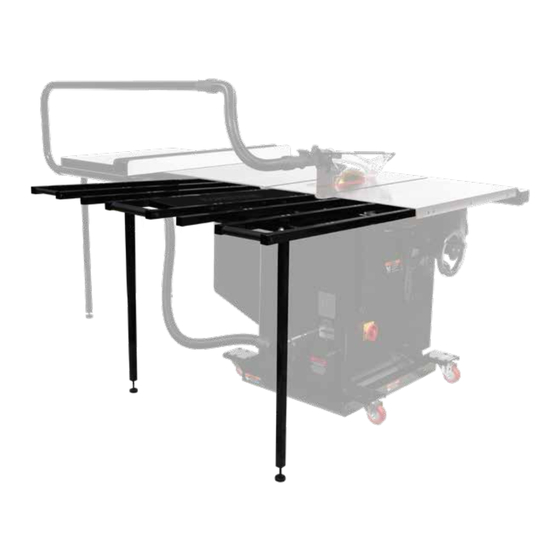
PRODUCT SPECIFICATIONS PAGES: The SawStop Folding Outfeed Table can be mounted to your SawStop saw with or without the left extension wing, depending on your needs. The SawStop Folding Outfeed Table is compatible with the SawStop Sliding Crosscut Tables (TSA-SA48 and TSA-SA70). - Page 7 Left extension wing...
-
Page 8: Parts Inventory
Folding Outfeed Table is located in the Hardware Packs and is shipped in the Folding Outfeed Table box. Please unpack the parts carefully and confirm you have received each item on the list. HARDWARE PACK TSA-FOT OWNER’S MANUAL... -
Page 9: Tools Needed
M6 x 35 Socket Head Cap Screw (4) M10 x 20 Set Screw (4) M6 x 16 Washer (36) M6 Lock Nut (8) Clamp Mounting Bracket (4) Tools Needed • 10mm Wrench • 13mm Wrench • Level or Straightedge TSA-FOT OWNER’S MANUAL... -
Page 10: Before You Begin
BEFORE YOU BEGIN PAGES: The drawings show how to assemble the Folding Outfeed Table for the SawStop T-Glide Fence System – Industrial Series (CBFR and TGI2), but the assembly instructions for the SawStop T-Glide Fence System - Professional Series (TGP2) and SawStop Premium Fence Assembly (PFA) are similar, and any differences are explained. - Page 11 WITH WING If installing the Folding Outfeed Table WITH the left extension wing, proceed to page 7. WITHOUT WING If installing the Folding Outfeed Table WITHOUT the left extension wing, proceed to page 33. TSA-FOT OWNER’S MANUAL...
-
Page 12: Installing With The Extension Wing
The rear three holes on each side of the table tubes are used for mounting the insert table (see Fig. 1 below for reference). Table support tube mounting holes Table roller mounting hole Table support tube mounting holes Rear rail clamp mounting hole Insert table mounting holes Fig. 1 TSA-FOT OWNER’S MANUAL... - Page 13 (see Fig. 2 or the exploded view on page 57 for reference). Fig. 2 TSA-FOT OWNER’S MANUAL...
- Page 14 M6 x 16 washer and an M6 lock nut. Use a 5mm hex L-wrench and a 10mm wrench to tighten the lock nut. Repeat this process for the other two exposed mounting holes in the table tube attached to the large table roller and the insert table. Fig. 4 TSA-FOT OWNER’S MANUAL...
- Page 15 Turn the assembly over, so the large table support tube mounting holes and the “SawStop” text are on top. Use a straight-edge to make sure the top surface of the insert table (D) does not extend above the top surfaces of the table tubes (A).
- Page 16 Press the ball bearings into the table roller bushings. Repeat this process with another two table tubes (A) and the remaining small table roller (E). Set the table tubes with the small table rollers aside. Table Roller Bushing Fig. 6 TSA-FOT OWNER’S MANUAL...
- Page 17 DO NOT OVER TIGHTEN THE LOCK NUTS. THE CLAMP MOUNTING BRACKETS SHOULD BE ABLE TO PIVOT RELATIVE TO THE REAR RAIL CLAMPS. Upper hole Hole in top of clamp Lower hole Hole in bottom of clamp Fig. 7 TSA-FOT OWNER’S MANUAL...
- Page 18 THAT THE SET SCREW IS INSTALLED IN THE TOP OF THE REAR RAIL CLAMP, SINCE IT COULD SCRATCH THE MOTOR COVER IF INSTALLED IN THE BOTTOM OF THE REAR RAIL CLAMP. Upper hole Hole in top of clamp Lower hole Hole in bottom of clamp Fig. 8 TSA-FOT OWNER’S MANUAL...
- Page 19 DO NOT OVER TIGHTEN THE LOCK NUTS. THE CLAMP MOUNTING BRACKETS SHOULD BE ABLE TO PIVOT RELATIVE TO THE REAR RAIL CLAMPS. Upper hole Hole in top of clamp Lower hole Hole in bottom of clamp Fig. 9 TSA-FOT OWNER’S MANUAL...
- Page 20 Fig. 10 No procedure is needed for the other two rear rail clamps at this time, as you will need to check (and potentially adjust) the height of the table tubes relative to the table saw. TSA-FOT OWNER’S MANUAL...
- Page 21 M6 lock nut and tighten the lock nut. Alternatively, if a table tube is too low relative to the saw table, move one of the washers from below the clamp to above the clamp. TSA-FOT OWNER’S MANUAL...
- Page 22 Insert an M6 x 20 socket head cap screw down through the clamp mounting holes in the table tube, then through the same number of M6 x 16 washers you needed between the TSA-FOT OWNER’S MANUAL...
- Page 23 (from the perspective of a user of the table saw), and the other should have the rear rail clamp on the right table tube (see Fig. 13 for reference). Fig. 13 TSA-FOT OWNER’S MANUAL...
- Page 24 Repeat this process for the other two table support tubes. TSA-FOT OWNER’S MANUAL...
- Page 25 WITH WING Table tube mounting holes Support leg mounting holes Fig. 15 TABLE SAW Fig. 16 TSA-FOT OWNER’S MANUAL...
- Page 26 There should be one set of aligned holes and five non-aligned holes to the left of the table tubes, two non-aligned holes between the table tubes, and one set of aligned holes and five non-aligned holes to the right of the table tubes. Fig. 17 TSA-FOT OWNER’S MANUAL...
- Page 27 Repeat this process for the other two table support tubes. Table tube mounting holes Support leg mounting holes Fig. 18 TABLE SAW Fig. 19 TSA-FOT OWNER’S MANUAL...
- Page 28 There should be three sets of aligned holes in the overlapping portion to the right of the table tubes, and two more solitary holes in the non-overlapping portion of the table support tube to the right of the table tubes. Fig. 20 TSA-FOT OWNER’S MANUAL...
- Page 29 M8 x 20 washer, then through the exposed mounting holes in the support leg, another M8 x 20 washer, the exposed mounting holes in the table support tube, another M8 x 20 washer, and an M8 lock nut (see Fig. 22). Fig. 22 TSA-FOT OWNER’S MANUAL...
- Page 30 They need to remain loose so you can align the outfeed table to the table saw. Pivot the support legs down so the leveling feet contact the ground. See Fig. 23 below. Fig. 23 TSA-FOT OWNER’S MANUAL...
- Page 31 M6 x 16 washer and an M6 lock nut. Do not tighten the lock nut at this time. Repeat this process for the remaining seven sets of mounting holes in the two solitary table tubes and table support tubes. See Fig. 24 below for reference. When finished, skip ahead to page 28. Fig. 24 TSA-FOT OWNER’S MANUAL...
- Page 32 M6 x 16 washer and an M6 lock nut. Do not tighten the lock nut at this time. Repeat this process for the remaining seven sets of mounting holes in the two solitary table tubes and table support tubes. See Fig. 25 below for reference. Fig. 25 TSA-FOT OWNER’S MANUAL...
- Page 33 M6 x 16 washer and an M6 lock nut. Do not tighten the lock nut at this time. Repeat this process for the remaining three sets of mounting holes in the two table tubes and table support tubes. Fig. 26 TSA-FOT OWNER’S MANUAL...
- Page 34 M6 x 16 washer and an M6 lock nut. Do not tighten the lock nut at this time. Repeat this process for the remaining three sets of mounting holes in the two table tubes and table support tubes. Fig. 27 TSA-FOT OWNER’S MANUAL...
- Page 35 Use a 5mm hex L-wrench to tighten the three M10 x 20 set screws to secure the Folding Outfeed Table to the rear rail. Use a straightedge to recheck that the tops of the table tubes are flush or just beneath the top of the saw table and make any necessary adjustments. TSA-FOT OWNER’S MANUAL...
- Page 36 Repeat this process for the remaining three sets of mounting holes in the two table tubes and table support tubes. Use a 5mm hex L-wrench to tighten the M10 x 20 set screw to secure the rear rail clamp. Fig. 29 TSA-FOT OWNER’S MANUAL...
- Page 37 Use a 5mm hex L-wrench and a 13mm wrench to tighten the 24 socket head cap screws and lock nuts securing the table tubes to the table support tubes. Fig. 31 Congratulations! Assembly of your Folding Outfeed Table is complete. TSA-FOT OWNER’S MANUAL...
-
Page 38: Installing Without The Extension Wing
The rear three holes on each side of the table tube are used for mounting the insert table (see Fig. 32 for reference). Table support tube mounting holes Table roller mounting hole Table support tube mounting holes Rear rail clamp mounting hole Insert table mounting holes Fig. 32 TSA-FOT OWNER’S MANUAL... - Page 39 (see Fig. 33 or the exploded view on page 57 for reference). Fig. 33 TSA-FOT OWNER’S MANUAL...
- Page 40 M6 x 16 washer and an M6 lock nut. Use a 5mm hex L-wrench and a 10mm wrench to tighten the lock nut. Repeat this process for the other two exposed mounting holes in the table tube attached to the large table roller and the insert table. Fig. 35 TSA-FOT OWNER’S MANUAL...
- Page 41 Turn the assembly over, so the large table support tube mounting holes and the “SawStop” text are on top. Use a straight-edge to make sure the top surface of the insert table (D) does not extend above the top surfaces of the table tubes (A).
- Page 42 Press the ball bearings into the table roller bushings. Set the table tubes with the small table rollers aside. Table Roller Bushing Fig. 37 TSA-FOT OWNER’S MANUAL...
- Page 43 DO NOT OVER TIGHTEN THE LOCK NUTS. THE CLAMP MOUNTING BRACKETS SHOULD BE ABLE TO PIVOT RELATIVE TO THE REAR RAIL CLAMPS. Upper hole Hole in top of clamp Lower hole Hole in bottom of clamp Fig. 38 TSA-FOT OWNER’S MANUAL...
- Page 44 THAT THE SET SCREW IS INSTALLED IN THE TOP OF THE REAR RAIL CLAMP, SINCE IT COULD SCRATCH THE MOTOR COVER IF INSTALLED IN THE BOTTOM OF THE REAR RAIL CLAMP. Upper hole Hole in top of clamp Lower hole Hole in bottom of clamp Fig. 39 TSA-FOT OWNER’S MANUAL...
- Page 45 DO NOT OVER TIGHTEN THE LOCK NUTS. THE CLAMP MOUNTING BRACKETS SHOULD BE ABLE TO PIVOT RELATIVE TO THE REAR RAIL CLAMPS. Upper hole Hole in top of clamp Lower hole Hole in bottom of clamp Fig. 40 TSA-FOT OWNER’S MANUAL...
- Page 46 Fig. 41 No procedure is needed for the other rear rail clamp at this time, as you will need to check (and potentially adjust) the height of the table tubes relative to the table saw. TSA-FOT OWNER’S MANUAL...
- Page 47 M6 lock nut and tighten the lock nut. Alternatively, if a table tube is too low relative to the saw table, move one of the washers from below the clamp to above the clamp. TSA-FOT OWNER’S MANUAL...
- Page 48 (from the perspective of the user of the table saw), and the open end of the clamp extends away from the small table roller (see Fig. 44 for reference). TSA-FOT OWNER’S MANUAL...
- Page 49 Install a tube end cap into the open ends of the two table tubes attached to the small table roller and into the open ends of two solitary table tubes (not attached to table rollers). Fig. 45 TSA-FOT OWNER’S MANUAL...
- Page 50 There should be two holes to the left of the insert table, one hole between the table tubes, and five holes to the right of the insert table. TSA-FOT OWNER’S MANUAL...
- Page 51 WITHOUT WING Fig. 47 Fig. 48 TSA-FOT OWNER’S MANUAL...
- Page 52 You may need to pivot the first support leg partially out of the way in order to install the washer and lock nut for the second support leg. Fig. 50 TSA-FOT OWNER’S MANUAL...
- Page 53 They need to remain loose so you can align the outfeed table to the table saw. Pivot the support legs down so the leveling feet contact the ground. Fig. 51 TSA-FOT OWNER’S MANUAL...
- Page 54 M6 x 16 washer and an M6 lock nut. Do not tighten the nut at this time. Repeat this process for the remaining three sets of mounting holes in the two solitary table tubes and table support tubes. Refer to Fig. 52 below. Fig. 52 TSA-FOT OWNER’S MANUAL...
- Page 55 M6 x 16 washer and an M6 lock nut. Do not tighten the lock nut at this time. Repeat this process for the remaining three sets of mounting holes in the two table tubes and table support tubes. Fig. 53 TSA-FOT OWNER’S MANUAL...
- Page 56 Additionally, you can disassemble the clamp and reassemble it with the clamp mounting bracket on the other side, which will allow you to switch the clamp to the other side of the table tube. Fig. 54 TSA-FOT OWNER’S MANUAL...
- Page 57 Press a tube end cap into the top of both support legs and into the outer ends of the four table support tubes. Fig. 55 TSA-FOT OWNER’S MANUAL...
- Page 58 Use a 5mm hex L-wrench and a 13mm wrench to tighten the 12 socket head cap screws and lock nuts securing the table tubes to the table support tubes. Fig. 56 Congratulations! Assembly of your Folding Outfeed Table is complete. TSA-FOT OWNER’S MANUAL...
-
Page 59: Installing On A 36" Saw With Overarm Dust Collection
Folding Outfeed Table and the TSA-ODC Overarm Dust Collection system are both mounted on the rear rail. For both to mount on the rail as required, while allowing for folding of the TSA-FOT, you must either: 1. Cut the lower Overarm Dust Collection Tube (Procedure listed below) - or - 2. - Page 60 12” from the edge of your extension table. Refer to Fig. 58 below. Tube shifted 12” out to allow table to fold Fig. 58 TSA-FOT OWNER’S MANUAL...
-
Page 61: Positioning The Outfeed Table In The Folded Position
To adjust the height of the Folding Outfeed Table, screw the leveling feet in or out of the support legs as needed and secure them into position by screwing the hex nut snug against the bottom of the support leg. TSA-FOT OWNER’S MANUAL... -
Page 62: Reference
This warranty is void if the Folding Outfeed Table system or any portion of the Folding Outfeed Table system is modified without the prior written permission of SawStop, LLC, or if the Folding Outfeed Table system is located or has been used outside of the country where the authorized SawStop distributor from whom the Folding Outfeed Table system was purchased resides. -
Page 63: Safety
4. Wear proper apparel when using the saw and Folding Outfeed Table. Do not wear loose clothing, gloves, neckties, rings, bracelets, or other jewelry which may get caught in moving parts. Non-slip footwear is recommended. Wear a protective hair covering to contain long hair. TSA-FOT OWNER’S MANUAL... - Page 64 Outfeed Table. Any parts that are damaged should be properly repaired or replaced. 10. Never use the Folding Outfeed Table if your saw is raised off the floor (i.e. if the wheels on a mobile base are supporting the saw). TSA-FOT OWNER’S MANUAL...
- Page 65 This page is intentionally blank. TSA-FOT OWNER’S MANUAL...
-
Page 66: Exploded View
Exploded View Folding Outfeed Table Owner’s Manual TSA-FOT OWNER’S MANUAL... -
Page 67: Parts List
TSA-FOT-020 M8 x 1.25 x 9 Lock Nut TSA-FOT-021 Support Leg TSA-FOT-022 M8 x 1.25 Hex Nut TSA-FOT-023 Leveling Foot TSA-FOT-024 5mm Hex L-Wrench TSA-FOT-025 Folding Outfeed Table Owner's Manual TSA-FOT-026 Folding Outfeed Table Hardware Pack TSA-FOT-033 TSA-FOT OWNER’S MANUAL... -
Page 68: Replacement Roller Kits
Replacement Roller Kits The following replacement roller kits are available for use with your SawStop Folding Outfeed Table. Contact your local authorized SawStop Dealer or visit www.sawstop.com for more information. • Small Table Roller Kit P/N: TSA-FOT-027 Parts and Hardware Included: M6 x 1.0 x 45 Socket Head Cap Screw (2) - Page 69 This page is intentionally blank. TSA-FOT OWNER’S MANUAL...
- Page 70 This page is intentionally blank. TSA-FOT OWNER’S MANUAL...
- Page 71 This page is intentionally blank. TSA-FOT OWNER’S MANUAL...
- Page 72 SawStop, LLC 11555 SW Myslony St | Tualatin, Oregon 97062 USA www.sawstop.com Main Phone: (503) 570-3200 Service: (503) 582-9934 Fax: (503) 570-3303 Email: info@sawstop.com January 2018 - V18 M TBL 19 0004 00...
Need help?
Do you have a question about the TSA-FOT and is the answer not in the manual?
Questions and answers