SawStop RT-TGP Owner's Manual

SawStop RT-TGP Owner's Manual

27” router table assemblies

Advertisement

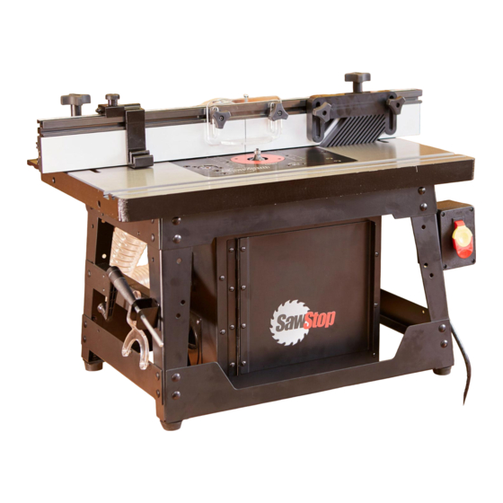
27" ROUTER TABLE ASSEMBLIES
OWNER'S MANUAL
MODEL RT-TGP/RT-BT

Advertisement

Table of Contents
loading

Summary of Contents for SawStop RT-TGP

  • Page 1 27” ROUTER TABLE ASSEMBLIES OWNER’S MANUAL MODEL RT-TGP/RT-BT...
  • Page 2 The Four-Post Router Lift with Lock and Downdraft Dust Collection Box for Router Lift are not included and your Router Table setup may look different. SawStop, the SawStop blade logo, and the configuration of this product are either registered trademarks or trademarks of SawStop, LLC. Software copyright by...
  • Page 3 TO OUR CUSTOMERS Thank you for purchasing the SawStop Benchtop Router Table Assembly or TGP2 In-Line Router Table Assembly. We are confident you will be pleased with this assembly’s quality and performance. This manual tells you more about the Benchtop Router Table Assembly and TGP2 In-Line Router Table Assembly for the Professional Cabinet Saw (PCS) or Contractor Saw (CNS) and how to operate and maintain them.
  • Page 4 HOW TO GET HELP Missing Parts? Have Questions? Our technical support team is standing by M-F, 6:30am-5pm PST to help with whatever you need. Give us a call at 503.582.9934 Email us at SERVICE@SAWSTOP.COM...
  • Page 5: Table Of Contents

    TABLE OF CONTENTS Product Specifications................Assembly Options.................. Benchtop Stand ......................In-Line Left of Left Wing (PCS or CNS)................In-Line Right: Between 36” Rails (PCS ONLY)............... In-Line Right: Between 52” Rails (PCS ONLY)............... Parts Inventory..................Parts & Hardware Lists..................... Assembly & Installation................Assembling the Table......................
  • Page 6: Product Specifications

    ½” at top, Width of Front T-Slot ⁄ ” at bottom Rear T-Slot to Arbor Center 5” 1” at top, Width of Rear T-Slot ¾” at bottom 27” Fence Assembly Length 30 ¾” Height 3 ½” Depth 4” RT-TGP/RT-BT OWNER’S MANUAL...
  • Page 7: Assembly Options

    The 27” x 16” Cast Iron Router Table can be mounted to the Benchtop Stand or to your SawStop table saw in any of four different configurations depending on your needs. The 27” Fence Assembly for Router Tables is compatible with all four configurations.
  • Page 8: In-Line Left Of Left Wing (Pcs Or Cns)

    Professional Cabinet Saw (PCS) Contractor Saw (CNS) The 27” x 16” Cast Iron Router Table is only compatible with the SawStop Contractor Saw if cast iron wings are installed. The standard stamped wings on the Contractor Saw cannot support the weight of the 27”...
  • Page 9: In-Line Right: Between 36" Rails (Pcs Only)

    This configuration is installed in place of the extension table, and minimizes the total footprint of your SawStop table saw and router table assembly. An intermediate cast iron wing (sold separately) can be installed to fill the gap between the right cast iron wing and the router table.
  • Page 10: Parts Inventory

    M6 x 1.0 x 40 Flat Head Phillips Screw (10) You will also need the following tools to complete the 27” x 16” Cast Iron Router Table assembly: • Phillips Head Screwdriver See Exploded View #1 on page 49 for more information. RT-TGP/RT-BT OWNER’S MANUAL...
  • Page 11 You will also need the following tools to complete the Benchtop Stand assembly: • • Phillips Head Screwdriver 10mm Wrench • • 8mm Wrench (x2) 5mm Hex Wrench See Exploded View #2 on page 51 for more information. RT-TGP/RT-BT OWNER’S MANUAL...
  • Page 12 M8 x 1.25 Hex Nut (2) Foot (2) A A A You will also need the following tools to complete the Support Legs assembly: • 13mm Wrench See Exploded View #3 on page 53 for more information. RT-TGP/RT-BT OWNER’S MANUAL...
  • Page 13 You will also need the following tools to complete the Power Switch for Router Tables assembly: • • 5mm Hex Wrench Phillips Head Screwdriver • • Level or Straight Edge 16mm Wrench (x2) • 13mm Wrench (x2) See Exploded View #4 on page 55 for more information. RT-TGP/RT-BT OWNER’S MANUAL...
  • Page 14 M6 x 1.0 x 35 T-Bolt (8) Router Fence Guard Spacer (2) You will also need the following tools to complete the 27” Fence Assembly for Router Tables: • Phillips Head Screwdriver See Exploded View #5 on page 57 for more information. RT-TGP/RT-BT OWNER’S MANUAL...
  • Page 15: Parts & Hardware Lists

    Exploded View #4: 32” Power Switch for In-Line Router Tables – See page 55 • Exploded View #5: 27” Fence Assembly for Router Tables – See page 57 • Exploded View #6: Intermediate Cast Iron Wing – See page 59 RT-TGP/RT-BT OWNER’S MANUAL...
  • Page 16: Assembly & Installation

    The 2 holes in the center of the opening (shown in red) do not receive leveling screws; they will be used later to attach the router lift to the router table. RT-TGP/RT-BT OWNER’S MANUAL...
  • Page 17 For mounting to the left extension wing of your Professional Cabinet Saw or Contractor Saw, proceed to page 19. The router table is only compatible with the SawStop Contractor Saw if cast iron wings are installed. The standard stamped wings on the Contractor Saw cannot support the weight of the router table.
  • Page 18: Assembling The Benchtop Stand

    ALIGN THE BENCHTOP STAND WITH THOSE HOLES, AND MOUNT THE BENCHTOP STAND TO THE TABLE USING A BOLT, TWO FLAT WASHERS, A LOCK WASHER, AND A HEX NUT (OR A BOLT, TWO FLAT WASHERS, AND A LOCK NUT) ON EACH STAND LEG. RT-TGP/RT-BT OWNER’S MANUAL...
  • Page 19 (M), eight washers (J), and eight hex nuts (I). Only finger tighten the nuts at this time. Leaving the nuts loose will make it easier to align holes as you assemble the rest of the stand. RT-TGP/RT-BT OWNER’S MANUAL...
  • Page 20 Make sure that the brackets are on the outside of the legs. Do not fully tighten the nuts. Repeat the prior step to attach the remaining upper side bracket (C) and lower side bracket (E) to the opposite side of the stand. RT-TGP/RT-BT OWNER’S MANUAL...
  • Page 21 Use a Phillips screwdriver to hold the screws still, and use an 8mm wrench to tighten the nuts against the tool storage plate. RT-TGP/RT-BT OWNER’S MANUAL...
  • Page 22 Benchtop Stand hardware bag. They will be used to attach the benchtop stand to the router table. Make sure the switchbox assembly is facing the same way as the “SawStop” logo on the front of the stand. RT-TGP/RT-BT OWNER’S MANUAL...
  • Page 23: Installing The Table On The Benchtop Stand

    Turn over the table and stand, so the stand rests on the four support feet. Congratulations! You have completed the 27” x 16” Cast Iron Router Table – Benchtop Stand Assembly and Installation. Continue to page 40 for next steps. RT-TGP/RT-BT OWNER’S MANUAL...
  • Page 24: Assembling And Installing The Support Legs And Power Switch

    Thread a hex nut (3.2) all the way onto a foot (3.3), then thread the foot all the way into the base of a support leg (3.1). Repeat this process with another hex nut, foot, and support leg. RT-TGP/RT-BT OWNER’S MANUAL...
  • Page 25 Align two of the holes in the other support leg with the two holes on the left side of the leg mounting bracket (4.7) (from the perspective of the flat edge of the bracket). RT-TGP/RT-BT OWNER’S MANUAL...
  • Page 26 (4.12) through one of the two smaller lock washers (4.9) and a washer (4.10), then through the exposed mounting holes in the handle mounting bracket and leg mounting bracket. Use a Phillips screwdriver to secure the 4.12 screw. 4.10 RT-TGP/RT-BT OWNER’S MANUAL...
  • Page 27 (either the switchbox or the handle mounting bracket) facing towards the front of the table so it will be accessible when the table is flipped back over and installed on your saw. RT-TGP/RT-BT OWNER’S MANUAL...
  • Page 28 27 and then proceed to page 28. • For mounting in-line right: between Professional Cabinet Saw 52” rails, verify your rails on page 27 and then proceed to page 34. RT-TGP/RT-BT OWNER’S MANUAL...
  • Page 29: Installing In-Line Left Of Left Wing (Pcs Or Cns)

    Align four of the mounting holes in the router table (indicated by the red arrows in Figure A) with the four holes in the left extension wing of your saw (as indicated by the red arrows in Figure B). RT-TGP/RT-BT OWNER’S MANUAL...
  • Page 30 13mm wrenches to tighten the bolt and hex nut closest to the front of the extension wing. Repeat the process at the rear of the extension wing, then recheck both ends and tighten the two center bolts and hex nuts. RT-TGP/RT-BT OWNER’S MANUAL...
  • Page 31 Then use a 13mm wrench to tighten the hex nuts (3.2) up against the bottoms of the support legs. Congratulations! You have completed the In-Line Left of Left Wing setup. Continue to page 40 for the next steps. RT-TGP/RT-BT OWNER’S MANUAL...
  • Page 32: Rail Requirements: In-Line Right Of Pcs Right Wing

    • Install your In-Line Router Table left of the left wing • Purchase RT-Ready Replacement Rails (in green below) • Modify your existing rails. NOTE: SawStop-approved installation requires using SawStop- manufactured RT rails. No cut templates for rail modification are available from SawStop. 36” Rails REAR RAIL...
  • Page 33: Installing In-Line Right: Between Pcs 36" Rails

    5mm Hex Wrench Sold Separately: Intermediate Cast Iron Wing and Accompanying Hardware Sold Separately: 36” RT-Ready TGP2 SawStop rails. Refer to the figures on the previous page for reference: • SawStop T-Glide Fence System - 36” Replacement Rails for In-Line Router Table (No Tube), Part Number: RT-TGP2-L-R36A •...
  • Page 34 Then install four washers, four lock washers, and four hex nuts (in that order) on the bolts. Only finger tighten the nuts at this time. RT-TGP/RT-BT OWNER’S MANUAL...
  • Page 35 Repeat the process at the rear of the extension wing, then recheck both ends and tighten the two center bolts and hex nuts. RT-TGP/RT-BT OWNER’S MANUAL...
  • Page 36 (4.14), then through the intermediate cast iron wing and router 4.14 4.13 table. Secure the bolts with four more 4.16 4.15 washers (4.14), four lock washers (4.15), and four hex nuts (4.16). Only finger tighten the nuts at this time. RT-TGP/RT-BT OWNER’S MANUAL...
  • Page 37 (4.22). Insert a flat head socket screw (4.17) through both holes in the front rail and router table. Secure each screw with a washer (4.18), a lock washer (4.19), and a hex nut (4.20). 4.18 4.19 4.20 RT-TGP/RT-BT OWNER’S MANUAL...
  • Page 38 It is very important to install and align the main tube correctly. Congratulations! You have completed the In-Line Right: Between PCS 36” Rails Installation. Continue to page 40 for the next steps. RT-TGP/RT-BT OWNER’S MANUAL...
  • Page 39: Installing In-Line Right: Between Pcs 52" Rails

    Drill 3/8” Drill Bit Sold Separately: 36” Extension Table Sold Separately: 52” RT-Ready TGP2 SawStop rails. Refer to the figures on page 27 for reference: • SawStop T-Glide Fence System - 52” Replacement Rails for In-Line Router Table (No Tube), Part Number: RT-TGP2-L-R52A •...
  • Page 40 Mark the to rear rail extension table in the center of each of rear rail the holes in the front and rear rails. front rail clamp table to front rail RT-TGP/RT-BT OWNER’S MANUAL...
  • Page 41 There are two sets of holes in the edge of your router table. Mark the 36” extension table in the center of each of the three lower holes in the router table. Then set the router table (and attached support legs) aside. RT-TGP/RT-BT OWNER’S MANUAL...
  • Page 42 (4.14), then through the router table and 36” extension table. Secure the bolts with three more washers (4.14), three lock washers (4.15), and three hex nuts (4.16). Only finger tighten the hex nuts 4.16 at this time. 4.15 4.14 4.13 RT-TGP/RT-BT OWNER’S MANUAL...
  • Page 43 Adjust the feet in the support legs until they contact the ground and keep the router table level. Then use a 13mm wrench to tighten the hex nuts (3.2) up against the bottoms of the support legs. RT-TGP/RT-BT OWNER’S MANUAL...
  • Page 44 It is very important to install and align the front tube correctly. Congratulations! You have completed the In-Line Right: Between PCS 52” Rails Installation. Continue to the following page for the next steps. RT-TGP/RT-BT OWNER’S MANUAL...
  • Page 45: Assembling The Fence

    T-slot on the back of the router table fence (5.1) until the dust port is aligned with the large opening in the back of the fence. Use a Phillips screwdriver to tighten the screws to secure the dust port to the router table fence. RT-TGP/RT-BT OWNER’S MANUAL...
  • Page 46 T-bolts installed in Step 3. 5.14 Slide the other router fence face plate onto the other three T-bolts installed in Step 3. The two router fence face plates should now completely cover the front of the router fence. RT-TGP/RT-BT OWNER’S MANUAL...
  • Page 47 Secure each T-bolt with one of the two remaining smaller washers (5.7) and a fence face plate lock knob (5.6), but do not tighten the lock knobs. RT-TGP/RT-BT OWNER’S MANUAL...
  • Page 48 If you do NOT have the Dust Collection Box, use a 2 ½” dust hose (not provided) and two dust hose clamps (not provided) to attach the 2 1/2” dust port directly to a dust collection system. RT-TGP/RT-BT OWNER’S MANUAL...
  • Page 49 Then re-tighten the three lock knobs to secure the fence face plate in place. Congratulations! You have completed the assembly for the 27” Fence Assembly for Router Tables. Your router table setup is now complete. RT-TGP/RT-BT OWNER’S MANUAL...
  • Page 50: Reference

    PAGES: 45-60 Warranty SawStop warrants to the original retail purchaser of a new Benchtop Router Table Assembly/TGP2 In-Line Router Table Assembly from an authorized SawStop distributor that the Benchtop Router Table Assembly/TGP2 In-Line Router Table Assembly will be free from defects in material and workmanship for ONE YEAR from the date of purchase.
  • Page 51: Safety

    TGP2 In-Line Router Table Assembly. Do not wear loose clothing, gloves, neckties, rings, bracelets, or other jewelry which may get caught in moving parts. Non-slip footwear is recommended. Wear a protective hair covering to contain long hair. RT-TGP/RT-BT OWNER’S MANUAL...
  • Page 52 Assembly if your saw is raised off the floor (i.e. if the wheels on a mobile base are supporting the saw) and the Benchtop Router Table Assembly/TGP2 In-Line Router Table Assembly is installed in the in-line configuration. RT-TGP/RT-BT OWNER’S MANUAL...
  • Page 53 This page is intentionally blank. RT-TGP/RT-BT OWNER’S MANUAL...
  • Page 54: Exploded View 1: Cast Iron Router Table (Rt-C27)

    Exploded View 1: 27” x 16” Cast Iron Router Table (RT-C27) 27” Router Table Assemblies Owner’s Manual RT-C27 27” x 16” Cast Iron Table RT-TGP/RT-BT OWNER’S MANUAL...
  • Page 55: Parts List 1: Cast Iron Router Table (Rt-C27)

    Parts List 1: 27” x 16” Cast Iron Router Table (RT-C27) Description Part No. Qty. 27" Router Table Assembly RT-C27 27" Router Table RT-C27-001 M6 x 1.0 Hex Nut RT-C27-002 M6 x 1.0 x 40 Flat Head Phillips Screw RT-C27-003 27” Router Table Assemblies Owner’s Manual RT-C27-004 RT-TGP/RT-BT OWNER’S MANUAL...
  • Page 56: Exploded View 2: Benchtop Stand (Rt-Stb)

    Exploded View 2: Benchtop Stand for Router Table (RT-STB) RT-TGP/RT-BT OWNER’S MANUAL...
  • Page 57: Parts List 2: Benchtop Stand (Rt-Stb)

    M6 Lock Washer RT-STB-018 2.19 M6 x 1.0 x 16 Socket Head Cap Screw RT-STB-019 2.20 M5 x 0.8 x 8 Pan Head Phillips Screw RT-STB-020 2.21 M5 x 12 x 1 Washer RT-STB-021 2.22 SawStop Label RT-STB-022 RT-TGP/RT-BT OWNER’S MANUAL...
  • Page 58: Exploded View 3: Support Legs (Rt-St2)

    Exploded View 3: Support Legs for In-Line Router Tables (RT-ST2) Legs RT-TGP/RT-BT OWNER’S MANUAL...
  • Page 59: Parts List 3: Support Legs (Rt-St2)

    Parts List 3: Support Legs for In-Line Router Tables (RT-ST2) Description Part No. Qty. Support Legs for In-Line Router Tables RT-ST2 Support Leg RT-ST2-001 M8 x 1.25 Hex Nut RT-ST2-002 Foot RT-ST2-003 RT-TGP/RT-BT OWNER’S MANUAL...
  • Page 60: Exploded View 4: Power Switch (Rt-Psw)

    Exploded View 4: Power Switch for In-line Router Tables (RT-PSW) 4.21 Wing Mounting Hardware 4.13 4.14 4.15 4.10 4.12 4.16 4.11 4.10 4.22 Rail Mounting Hardware 4.17 4.18 4.19 4.20 RT-PSW Power Switch RT-TGP/RT-BT OWNER’S MANUAL...
  • Page 61: Parts List 4: Power Switch (Rt-Psw)

    M8 Lock Washer RT-PSW-019 4.20 M8 x 1.25 x 12 Hex Nut RT-PSW-020 4.21 Wing Mounting Hardware Bag (Includes 4.13-4.16) RT-PSW-021 4.22 Rail Mounting Hardware Bag (Includes 4.17-4.20) RT-PSW-022 4.23 Leg Mounting Hardware Bag (Includes 4.2-4.6, 4.7-4.12) RT-PSW-023 RT-TGP/RT-BT OWNER’S MANUAL...
  • Page 62: Exploded View 5: 27" Fence Assembly (Rt-F27)

    Exploded View 5: 27” Fence Assembly for Router Tables (RT-F27) RT-TGP/RT-BT OWNER’S MANUAL...
  • Page 63: Parts List 5: 27" Fence Assembly (Rt-F27)

    1/4"-20 x 3/4" Pan Head Phillips Screw RT-F27-011 5.12 1/4"-20 Square Nut RT-F27-012 5.13 Face Plate Spacer Bar RT-F27-013 5.14 Router Fence Face Plate RT-F27-014 5.15 Router Fence Guard RT-F27-015 5.16 Router Fence Guard Spacer RT-F27-016 5.17 Spring Pin (3mm x 10mm) RT-F27-017 RT-TGP/RT-BT OWNER’S MANUAL...
  • Page 64: Exploded View 6: Intermediate Cast Iron Wing (Rt-Icw)

    Exploded View 6: Intermediate Cast Iron Wing (RT-ICW) RT-TGP/RT-BT OWNER’S MANUAL...
  • Page 65: Parts List 6: Intermediate Cast Iron Wing (Rt-Icw)

    RT-ICW-001 M8 x 1.25 x 25 Flat Head Socket Screw RT-ICW-002 M8 x 20 x 2 Washer RT-ICW-003 M8 Lock Washer RT-ICW-004 M8 x 1.25 Hex Nut RT-ICW-005 M8 x 1.25 x 35 Hex Head Bolt RT-ICW-006 RT-TGP/RT-BT OWNER’S MANUAL...
  • Page 66: Available Accessories

    • Stackable featherboards for extra support for taller stock • Easy-grip lock knobs • Compatible with all SawStop Router Tables and Fences Single Vertical Feather Board for Router Tables RT-VFS • Holds your workpiece safely against the router fence for added stability •...
  • Page 67 Downdraft Dust Collection Box for Router Tables RT-DCB • Collects below-table dust • Connects to 4" dust tube • Compatible with all SawStop Router Tables Flip Stop for Router Fence RT-FLS • Designed to quickly give you accurate, repeatable measurements •...
  • Page 68 SawStop, LLC 11555 SW Myslony St | Tualatin, Oregon 97062 USA www.sawstop.com Main Phone: (503) 570-3200 Service: (503) 582-9934 Fax: (503) 570-3303 Email: info@sawstop.com January 2018 – BPV01 M RTR 19 0001 00...

This manual is also suitable for:

Rt-bt

Table of Contents