Table of Contents

Subscribe to Our Youtube Channel
Related Manuals for CEA DIGITECH vision PULSE Series


Summary of Contents for CEA DIGITECH vision PULSE Series
- Page 1 READ Operator’s manual CAREFULLY CEA COSTRUZIONI ELETTROMECCANICHE ANNETTONI S.p.A. C.so E. Filiberto, 27 - 23900 Lecco - Italy Tel. ++39.0341.22322 - Fax ++39.0341.422646 Cas. Post. (P.O.BOX) 205 E-mail: cea@ceaweld.com - web: www.ceaweld.com...
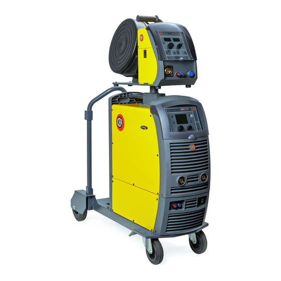
- Page 2 MULTI-FUNCTION INVERTER GENERATOR FOR MIG-MAG, Spot welding MMA, and TIG WELDING Interval welding The DIGITECH vision PULSE series of multi-function equip- ments are characterised by cutting edge, attractive design Aluminium welding combined with latest generation inverter technology and digi- tal welding control. Innovative, technologically advanced, ro-...
- Page 3 - WSC Wire start control. This arc striking control device pre- Technical data vents wire from sticking to the workpiece or torch nozzle and ensures precise and smooth arc striking, particularly The general technical data of the system are summarized in when welding aluminium.
- Page 4 The welding unit is characterized by the following classes: How to lift up the system • IP 23 S protection class indicates that the generator can be used in both interior and exterior environments. Strap the system safely and securely in the slings working from •...
- Page 5 FIG. A 2A - Connecting the cables - Welding with a POSITIVE MIG-MAG / PULSE MIG / DOUBLE POLE TORCH (Fig. B1) PULSE MIG Welding 1) The feeder - generator connecting cable is used to connect the welding machine to the feeder. To begin MIG-MAG / PULSE MIG / DOUBLE PULSE MIG weld- WARNING: Do not disconnect the wire-feeder until the ma- ing, carry out the following tasks (with the machine switched...
- Page 6 FIG. B2 • Interconnection cable on generator side: connect up • Wire feeder side connecting cable: connect the red and tubes to their rapid couplings (blue and red coloured) at blue pipes to their respective bulkhead grommets on the the back of the coolant system. rear panel of the feeder.
- Page 7 FIG. C 6) Once welding has been completed remove any slag, switch off the machine (which is only to be done when the fan is not running), and close the gas cylinder. Spot welding The substantial difference with MIG-MAG welding is essential- ly related to the torch and the adjustments that must be made on the DH control panel.
- Page 8 WELDING PARAMETERS 3) Make the adjustments and do the parameter settings on the control panel (for further information see the DH con- Table 3 shows some general indications for the choice of elec- trol panel manual). trode, based on the thickness of the parts to be welded. The 4) Open the gas cylinder and regulate the flow by adjusting values of current to use are shown in the table 5 with the re- the valve on the TIG torch by hand.
- Page 9 ations in the performance and reduce the safety level of the equipment. We are not liable for damage due to use of spare parts that are not original. Optional NOTE: The digital control unit of the generator is fitted with a control recognition device which allows it to identify which de- vice is connected and take action accordingly.
- Page 10 Wiring diagram 2101EA86...
- Page 11 Key to the electrical diagram •1 •2 •3 •4 •5 •6 •7 •8 •9 •10 F-EMC •11 •12 •13 •14 •15 MV1-2 •16 •17 •18 •19 S-INT DIG S-INV S-LINK •20 •21 •22 •23 •24 S-PS •1 SNUBBER capacitor for output diodes •2 Interconnec- tion cable connector •3 Cooling system power connector •4 Quick connection protection capacitor •5 Secondary diode •6 EMC filter •7 Mains switch •8 Secondary inductor •9 Pri-...
- Page 13 Lista ricambi LEGGERE ATTENTAMENTE Spare parts list READ CAREFULLY CEA COSTRUZIONI ELETTROMECCANICHE ANNETTONI S.p.A. C.so E. Filiberto, 27 - 23900 Lecco - Italy Tel. ++39.0341.22322 - Fax ++39.0341.422646 Cas. Post. (P.O.BOX) 205 e-mail: cea@ceaweld.com - web: www.ceaweld.com...
- Page 14 Manopola senza indice Ø29mm Ø29mm knob without index 468725 Adesivo logo CEA Ø30mm CEA logo sticker Ø30mm 352458 Pannello frontale senza adesivo logo CEA Ø30mm Front panel without CEA logo sticker Ø30mm 403611 Attacco rapido Quick connection 420685 Coperchio lato sinistro con adesivo logo CEA...
- Page 15 427883 Pressacavo con ghiera Cable clamp with lock ring 235948 Cavo alimentazione Mains cable 352459 Pannello posteriore senza adesivo logo CEA Ø30mm Rear panel without CEA logo sticker Ø30mm 453145 Connettore cavo interconnessione Interconnection cable connector 403611 Attacco rapido Quick connection...
- Page 16 DIGITECH vision Pos. Descrizione Description PULSE 3300 435760 Interruttore alimentazione Mains switch 427667 Filtro EMC EMC Filter 449578 Pianale superiore Upper plate 377133 Scheda condensatori Capacitors PCB 478786 Termostato secondario Secondary thermostat 377113 Scheda power source Power source PCB 413499 Cablaggio ausiliario Auxiliary wiring 463215...
- Page 17 Ø29mm Knob without index 468725 468725 Adesivo logo CEA Ø30mm CEA logo sticker Ø30mm Pannello frontale senza adesivo 352458 352458 Front panel without CEA logo sticker Ø30mm logo CEA Ø30mm 403617 403617 Attacco rapido Quick connection 420685 420685 Coperchio lato sinistro con adesivo logo CEA...
- Page 18 Pressacavo con ghiera Cable clamp with lock ring 235999 235943 Cavo alimentazione Mains cable Pannello posteriore senza 352459 352459 Rear panel without CEA logo sticker Ø30mm adesivo logo CEA Ø30mm 453145 453145 Connettore cavo interconnessione Interconnection cable connector 403617 403617 Attacco rapido...
- Page 20 IT Ordinazione dei pezzi di ricambio EN Ordering spare parts Per la richiesta di pezzi di ricambio indicare chiaramente: To ask for spare parts clearly state: 1) Il numero di codice del particolare 1) The code number of the piece 2) Il tipo di impianto 2) The type of device 3) La tensione e la frequenza che rileverete dalla targhetta...
- Page 25 Operator’s manual READ CAREFULLY CEA COSTRUZIONI ELETTROMECCANICHE ANNETTONI S.p.A. C.so E. Filiberto, 27 - 23900 Lecco - Italy Tel. ++39.0341.22322 - Fax ++39.0341.422646 Cas. Post. (P.O.BOX) 205 e-mail: cea@ceaweld.com - web: www.ceaweld.com...
-
Page 26: Table Of Contents
ENGLISH Introduction ..................4 General notes . - Page 27 MMA ..................39 1 - PROGRAM SELECTION Menu (PROGRAM) .
-
Page 28: Introduction
Introduction This manual describes the functions of the software operating the following control panels: • DH 33 + HT4. • DH 40 + HT4. • DH 50 + HT4. Functioning of the panels listed above is identical (the functions are the same but the characteristics differ depending on the type of machine they are fitted on (e.g.: current regulation field). -
Page 29: Welding Mode Selection Key
WELDING MODE SELECTION Key Each time this is pushed the following welding modes can be selected (only for pulsed and double pulsed MIG, synergic and manual welding processes) on the feeder (on the welding machine the welding mode is selected using a specific menu - see the appropriate paragraphs) according to a specific sequence: 2T LED 4T LED... -
Page 30: Switching On The Welding Machine
• The VISION S shows the SCREEN SAVER. CREEN • On both the HT4 displays for the wire feeder, “CEA” appears and scrolls continuously. VISION Screen HT4 Screen The SCREEN SAVER mode can be exited in one of the following ways: •... -
Page 31: Welding Process Selection Menu (Process)
WELDING PROCESS SELECTION Menu (PROCESS) “DH” CONTROL PANEL To access the PROCESS SELECTION Menu (PROCESS) push the MENU K MENU K ENTER/MEM K MIG PULSE MIG DUAL PULSE MIG/MAG SYNERGIC SX K DX K MIG/MAG MANUAL TIG LIFT 2011 Fe G3 SI-1 Ø 0.8 Ar 16-20% CO2 ENCODER K - SX ENCODER K... -
Page 32: Welding Mode Selection Menu (Mode)
2 - WELDING MODE SELECTION Menu (MODE) MIG pulse “DH” CONTROL PANEL To access the WELDING MODE SELECTION Menu (MODE) push the MENU K MENU K ENTER/MEM K TWO STROKE (2T) FOUR STROKE (4T) CRATER 2T SX K DX K CRATER 4T SPOT WELDING STITCH WELDING... -
Page 33: Special Functions Menu (Set Up Fx)
3 - SPECIAL FUNCTIONS Menu (SET UP Fx) MIG pulse “DH” CONTROL PANEL To access the SPECIAL FUNCTIONS Menu (SET UP Fx) push the MENU K MENU K ENTER/MEM K SX K DX K POST GAS 1.0 s DEFAULT 1011 Fe G3 SI-1 Ø 0.8 Ar 16-20% CO2 ENCODER K - SX ENCODER K... - Page 34 The SPECIAL FUNCTIONS (Fx) related to the MIG pulse process correspond as follows to those on the wire feeder: PARAMETER DISPLAY Screen - V Welding mode PARAMETER DISPLAY Special function Screen - A PRE GAS 0.1s (0.0 - 2.0)s ● ●...
-
Page 35: Pre-Setting
4 - PRE-SETTING MIG pulse “DH” CONTROL PANEL MENU K ENTER/MEM K 217 29.4 SX K DX K PROGRAM 1011 Fe G3 SI-1 Ø 0.8 Ar 16-20% CO2 ENCODER K - SX ENCODER K - DX VISION S CREEN Used to access the PROCESS SELECTION Menu (PROCESS) and subsequent menus, as MENU K applicable. -
Page 36: Welding
ENCODER K Adjusts the parameter displayed by the PARAMETER DISPLAY S - V. CREEN GAS K Activates the flow of gas. Only enables entering and exit afterwards from the SPECIAL FUNCTIONS Menu (SET UP SPECIAL FUNCTIONS (F Fx) on the HT4 panel and not on the DH panel. 5 - WELDING MIG pulse When welding takes place the fields in the displays show the same values as those included for pre-setting with the difference... - Page 37 “HT4” CONTROL PANEL PARAMETER DISPLAY S HOLD Function LED CREEN PARAMETER DISPLAY S CREEN PARAMETER SELECTION LED - A PARAMETER SELECTION LED - V PARAMETER SELECTION K PARAMETER SELECTION K ENCODER K ENCODER K WIRE K GAS K WELDING MODE SELECTION K SPECIAL FUNCTIONS (F WELDING MODE SELECTION LED SPECIAL FUNCTIONS (F...
-
Page 38: Hold
6 - HOLD MIG pulse When welding ends the fields in the display must show the same values that were displayed during welding, with the difference that they are now values defined as HOLD. In this phase the VISION S shows the HOLD box highlighted, while on the HT4 CREEN panel the HOLD F... - Page 39 “HT4” CONTROL PANEL PARAMETER DISPLAY S HOLD Function LED CREEN PARAMETER DISPLAY S CREEN PARAMETER SELECTION LED - A PARAMETER SELECTION LED - V PARAMETER SELECTION K PARAMETER SELECTION K ENCODER K ENCODER K WIRE K GAS K WELDING MODE SELECTION K SPECIAL FUNCTIONS (F WELDING MODE SELECTION LED SPECIAL FUNCTIONS (F...
-
Page 40: Mig Dual Pulse
MIG dual pulse 1 - PROGRAM SELECTION Menu (PROGRAM) MIG dual pulse “DH” CONTROL PANEL To access the PROGRAM SELECTION Menu (PROGRAM) push the MENU K MENU K ENTER/MEM K MATERIAL Ø 2011 Fe G3 SI-1 0.8 Ar 16-20% CO2 2012 Fe G3 SI-1 1.0 Ar 16-20% CO2 SX K... -
Page 41: Special Functions Menu (Set Up Fx)
“HT4” CONTROL PANEL To access the WELDING MODE SELECTION Menu (MODE) push the WELDING MODE SELECTION K PARAMETER DISPLAY S HOLD Function LED CREEN PARAMETER DISPLAY S CREEN PARAMETER SELECTION LED - A PARAMETER SELECTION LED - V PARAMETER SELECTION K PARAMETER SELECTION K ENCODER K ENCODER K... - Page 42 “HT4” CONTROL PANEL To access the SPECIAL FUNCTIONS Menu (SET UP Fx) push the SPECIAL FUNCTIONS (F PARAMETER DISPLAY S HOLD Function LED CREEN PARAMETER DISPLAY S CREEN PARAMETER SELECTION LED - A PARAMETER SELECTION LED - V PARAMETER SELECTION K PARAMETER SELECTION K ENCODER K ENCODER K...
- Page 43 PARAMETER DISPLAY Screen - V Welding mode PARAMETER DISPLAY Special function Screen - A FINAL CRATER TIME 0.0s (0.0 - 5.0)s ● BURN BACK -30 - +30 ● ● ● ● ● ● ● ● POST GAS 1.0s (0.0 - 10.0)s ●...
-
Page 44: Pre-Setting
4 - PRE-SETTING MIG dual pulse “DH” CONTROL PANEL MENU K ENTER/MEM K 217 29.4 SX K DX K PROGRAM 2011 Fe G3 SI-1 Ø 0.8 Ar 16-20% CO2 ENCODER K - SX ENCODER K - DX VISION S CREEN Used to access the PROCESS SELECTION Menu (PROCESS) and subsequent menus, as MENU K applicable. -
Page 45: Welding
ENCODER K Adjusts the parameter displayed by the PARAMETER DISPLAY S - V. CREEN GAS K Activates the flow of gas. Only enables entering and exit afterwards from the SPECIAL FUNCTIONS Menu (SET UP SPECIAL FUNCTIONS (F Fx) on the HT4 panel and not on the DH panel. 5 - WELDING MIG dual pulse When welding takes place the fields in the displays show the same values as those included for pre-setting with the difference... - Page 46 “HT4” CONTROL PANEL PARAMETER DISPLAY S HOLD Function LED CREEN PARAMETER DISPLAY S CREEN PARAMETER SELECTION LED - A PARAMETER SELECTION LED - V PARAMETER SELECTION K PARAMETER SELECTION K ENCODER K ENCODER K WIRE K GAS K WELDING MODE SELECTION K SPECIAL FUNCTIONS (F WELDING MODE SELECTION LED SPECIAL FUNCTIONS (F...
-
Page 47: Hold
6 - HOLD MIG dual pulse When welding ends the fields in the display must show the same values that were displayed during welding, with the difference that they are now values defined as HOLD. In this phase the VISION S shows the HOLD box highlighted, while on the HT4 CREEN panel the HOLD F... -
Page 48: Mig-Mag Synergic
WELDING MODE SELECTION K Scrolls the various welding modes in succession, interrupting the HOLD Function. WELDING MODE SELECTION LED The LED unit indicates the welding mode selected according to the VISION S CREEN HOLD F Flashes for a set time, informing the operator that the HOLD Function is active. UNCTION PARAMETER DISPLAY S Shows the parameter indicated by the PARAMETER SELECTION LED - V. -
Page 49: Welding Mode Selection Menu (Mode)
2 - WELDING MODE SELECTION Menu (MODE) MIG-MAG synergic “DH” CONTROL PANEL To access the WELDING MODE SELECTION Menu (MODE) push the MENU K MENU K ENTER/MEM K TWO STROKE (2T) FOUR STROKE (4T) CRATER 2T SX K DX K CRATER 4T SPOT WELDING STITCH WELDING... -
Page 50: Special Functions Menu (Set Up Fx)
3 - SPECIAL FUNCTIONS Menu (SET UP Fx) MIG-MAG synergic “DH” CONTROL PANEL To access the SPECIAL FUNCTIONS Menu (SET UP Fx) push the MENU K MENU K ENTER/MEM K SX K DX K PRE GAS 0.5 s DEFAULT 0203 CrNi Ø 1.2 98Ar2CO2 ENCODER K - SX ENCODER K... - Page 51 The SPECIAL FUNCTIONS (Fx) related to the Synergic MIG-MAG process correspond as follows to those on the wire feeder: PARAMETER DISPLAY Screen - V Welding mode PARAMETER DISPLAY Special function Screen - A PRE GAS 0.1s (0.0 - 2.0)s ● ●...
-
Page 52: Pre-Setting
4 - PRE-SETTING MIG-MAG synergic “DH” CONTROL PANEL MENU K ENTER/MEM K 217 24.3 SX K DX K PROGRAM 0163 Fe METAL CORED Ø 1.2 Ar-18CO2 ENCODER K - SX ENCODER K - DX VISION S CREEN Used to access the PROCESS SELECTION Menu (PROCESS) and subsequent menus, as MENU K applicable. -
Page 53: Welding
ENCODER K Adjusts the parameter displayed by the PARAMETER DISPLAY S - V. CREEN GAS K Activates the flow of gas. Only enables entering and exit afterwards from the SPECIAL FUNCTIONS Menu (SET UP SPECIAL FUNCTIONS (F Fx) on the HT4 panel and not on the DH panel. 5 - WELDING MIG-MAG synergic When welding takes place the fields in the displays show the same values as those included for pre-setting with the difference... - Page 54 “HT4” CONTROL PANEL PARAMETER DISPLAY S HOLD Function LED CREEN PARAMETER DISPLAY S CREEN PARAMETER SELECTION LED - A PARAMETER SELECTION LED - V PARAMETER SELECTION K PARAMETER SELECTION K ENCODER K ENCODER K WIRE K GAS K WELDING MODE SELECTION K SPECIAL FUNCTIONS (F WELDING MODE SELECTION LED SPECIAL FUNCTIONS (F...
-
Page 55: Hold
6 - HOLD MIG-MAG synergic When welding ends the fields in the display must show the same values that were displayed during welding, with the difference that they are now values defined as HOLD. In this phase the VISION S shows the HOLD box highlighted, while on the HT4 CREEN panel the HOLD F... -
Page 56: Mig-Mag Manual
WELDING MODE SELECTION K Scrolls the various welding modes in succession, interrupting the HOLD Function. WELDING MODE SELECTION LED The LED unit indicates the welding mode selected according to the VISION S CREEN HOLD F Flashes for a set time, informing the operator that the HOLD Function is active. UNCTION PARAMETER DISPLAY S Shows the parameter indicated by the PARAMETER SELECTION LED - V. -
Page 57: Special Functions Menu (Set Up Fx)
“HT4” CONTROL PANEL To access the WELDING MODE SELECTION Menu (MODE) push the MENU K PARAMETER DISPLAY S HOLD Function LED CREEN PARAMETER DISPLAY S CREEN PARAMETER SELECTION LED - A PARAMETER SELECTION LED - V PARAMETER SELECTION K PARAMETER SELECTION K ENCODER K ENCODER K WIRE K... - Page 58 “HT4” CONTROL PANEL To access the SPECIAL FUNCTIONS Menu (SET UP Fx) push the MENU K PARAMETER DISPLAY S HOLD Function LED CREEN PARAMETER DISPLAY S CREEN PARAMETER SELECTION LED - A PARAMETER SELECTION LED - V PARAMETER SELECTION K PARAMETER SELECTION K ENCODER K ENCODER K...
-
Page 59: Pre-Setting
PARAMETER DISPLAY Screen - V Welding mode PARAMETER DISPLAY Special function Screen - A FINAL CRATER TIME 0.0s (0.0 - 5.0)s ● BURN BACK -30 - +30 ● ● ● ● ● ● ● ● POST GAS 1.0s (0.0 - 10.0)s ●... -
Page 60: Welding
“HT4” CONTROL PANEL PARAMETER DISPLAY S HOLD Function LED CREEN PARAMETER DISPLAY S CREEN PARAMETER SELECTION LED - A PARAMETER SELECTION LED - V PARAMETER SELECTION K PARAMETER SELECTION K ENCODER K ENCODER K WIRE K GAS K WELDING MODE SELECTION K SPECIAL FUNCTIONS (F WELDING MODE SELECTION LED SPECIAL FUNCTIONS (F... - Page 61 Adjusts the WIRE SPEED ( ) parameter (the WELDING CURRENT ( ) cannot be adjusted). ENCODER K - SX In this case the values displayed become those pre-set. After a period of 3 seconds the values displayed go back to those measured if possible. Scrolls in succession WELDING VOLTAGE ( ) - ELECTRONIC INDUCTANCE ( ) only on DX K...
-
Page 62: Hold
5 - HOLD MIG-MAG manual When welding ends the fields in the display must show the same values that were displayed during welding, with the difference that they are now values defined as HOLD. In this phase the VISION S shows the HOLD box highlighted, while on the HT4 CREEN panel the H... -
Page 63: Mma
HOLD F Flashes for a set time, informing the operator that the HOLD Function is active. UNCTION PARAMETER DISPLAY S Shows the parameter indicated by the PARAMETER SELECTION LED - V. CREEN The LED unit indicates the welding parameter selected using the PARAMETER SELECTION K PARAMETER SELECTION LED - V - V. -
Page 64: Special Functions Menu (Set Up Fx)
2 - SPECIAL FUNCTIONS Menu (SET UP Fx) “DH” CONTROL PANEL To access the SPECIAL FUNCTIONS Menu (SET UP Fx) push the SPECIAL FUNCTIONS (F MENU K ENTER/MEM K SX K DX K HOT START DEFAULT 3200 MMA Cr Ni ENCODER K - SX ENCODER K... -
Page 65: Pre-Setting
The SPECIAL FUNCTIONS (Fx) related to the MMA process correspond as follows to those on the wire feeder: PARAMETER DISPLAY Screen - V Special function PARAMETER DISPLAY Screen - A Default Range HOT START (0 - 100) ARC FORCE (0 - 100) WARNING: •... -
Page 66: Welding
Shows the parameter indicated by the PARAMETER SELECTION LED - V. PARAMETER DISPLAY S CREEN The WELDING VOLTAGE shown is the measured voltage. The LED unit indicates the welding parameter selected using the PARAMETER SELECTION K PARAMETER SELECTION LED - V - V. -
Page 67: Hold
Adjust the value of the parameter WELDING CURRENT ( ). ENCODER K In this case the values displayed become those pre-set. After a period of 3 seconds the values displayed go back to those measured if possible. Shows the value (measured, if possible) for the parameter indicated by the PARAMETER PARAMETER DISPLAY S CREEN SELECTION LED - V. -
Page 68: Activating The Vrd Device
“HT4” CONTROL PANEL PARAMETER DISPLAY S HOLD Function LED CREEN PARAMETER DISPLAY S CREEN PARAMETER SELECTION LED - A PARAMETER SELECTION LED - V PARAMETER SELECTION K PARAMETER SELECTION K ENCODER K ENCODER K WIRE K GAS K WELDING MODE SELECTION K SPECIAL FUNCTIONS (F WELDING MODE SELECTION LED SPECIAL FUNCTIONS (F... -
Page 69: Tig Lift
TIG LIFT 1 - SPECIAL FUNCTIONS Menu (SET UP Fx) TIG LIFT “DH” CONTROL PANEL To access the SPECIAL FUNCTIONS Menu (SET UP Fx) push the SPECIAL FUNCTIONS (F MENU K ENTER/MEM K SX K DX K SLOPE UP 2.0 s DEFAULT ENCODER K - SX... -
Page 70: Pre-Setting
The SPECIAL FUNCTIONS (Fx) related to the TIG LIFT process correspond as follows to those on the wire feeder: PARAMETER DISPLAY Screen - V Special function PARAMETER DISPLAY Screen - A Default Range UP SLOPE 0.0s (0.0 - 5.0)s DOWN SLOPE 2.0s (0.0 - 8.0)s SWS VOLTAGE THRESHOLD... -
Page 71: Welding
PARAMETER SELECTION LED - V The LED unit shows the WELDING VOLTAGE ( ) switched on. Only enables entering and exit afterwards from the SPECIAL FUNCTIONS Menu (SET UP SPECIAL FUNCTIONS (F Fx) on the HT4 panel and not on the DH panel. 3 - WELDING TIG LIFT When welding takes place the fields in the displays show the same values as those included for pre-setting with the difference... -
Page 72: Hold
4 - HOLD TIG LIFT When welding ends the fields in the display must show the same values that were displayed during welding, with the difference that they are now values defined as HOLD. In this phase the VISION S shows the HOLD box highlighted, while on the HT4 CREEN panel the HOLD F... -
Page 73: Job
1 - Creating and saving / editing and overwriting a JOB “DH” CONTROL PANEL MENU K ENTER/MEM K 211 24.8 SX K DX K PROGRAM 0011 Fe G3 SI-1 Ø 0.8 Ar 16-20% CO2 ENCODER K - SX ENCODER K - DX VISION S CREEN... -
Page 74: Job Selection Menu (Job)
2 - JOB SELECTION Menu (JOB) WARNING: All the parameters saved within a JOB (including SPECIAL FUNCTIONS (Fx)) can be viewed but not edited! “DH” CONTROL PANEL To access the JOB SELECTION Menu (JOB) push the MENU K MENU K ENTER/MEM K PRG JOB PROCESS... -
Page 75: Pre-Setting
3 - PRE-SETTING WARNING: All the parameters saved within a JOB (including SPECIAL FUNCTIONS (Fx)) can be viewed but not edited! “DH” CONTROL PANEL MENU K ENTER/MEM K m/min 11.1 33.3 SX K DX K ENCODER K - SX ENCODER K - DX VISION S CREEN... -
Page 76: Welding
GAS K Activates the flow of gas. SPECIAL FUNCTIONS (F Used to access the SPECIAL FUNCTIONS (Fx) saved in the JOB selected. 4 - WELDING WARNING: All the parameters saved within a JOB (including SPECIAL FUNCTIONS (Fx)) can be viewed but not edited! “DH”... -
Page 77: Hold
5 - HOLD When welding ends the fields in the display must show the same values that were displayed during welding, with the difference that they are now values defined as HOLD. In this phase the VISION S shows the HOLD box highlighted, while on the HT4 CREEN panel the HOLD F LED flashes until the end of the HOLD Function. -
Page 78: Error Condition
The LED unit indicates the welding mode saved in the JOB selected, which is coherent with WELDING MODE SELECTION LED the VISION S CREEN HOLD F Flashes for a set time, informing the operator that the HOLD Function is active. UNCTION Shows the number for the JOB selected or the value for the parameter indicated by the PARAMETER DISPLAY S... -
Page 79: Setup Menu
“HT4” CONTROL PANEL PARAMETER DISPLAY S HOLD Function LED CREEN PARAMETER DISPLAY S CREEN PARAMETER SELECTION LED - A PARAMETER SELECTION LED - V PARAMETER SELECTION K PARAMETER SELECTION K ENCODER K ENCODER K WIRE K GAS K WELDING MODE SELECTION K SPECIAL FUNCTIONS (F WELDING MODE SELECTION LED SPECIAL FUNCTIONS (F... -
Page 80: Job Edit
The icons (sub-menus) available and that can be viewed within the SETUP Menu are: • JOB EDIT • PASSWORD • BLOCKS • CONFIG • FACTORY RESET • INFO • DATA IN-OUT • ERROR LOG ACCESSING THE SUB-MENUS To access the sub-menus included in the SETUP Menu, you must: •... -
Page 81: Password
PASSWORD SETUP Menu The purpose of this menu is to allow the operator to enter a PASSWORD for accessing the SETUP Menu. To access the PASSWORD Menu from the SETUP Menu: • Turn the ENCODER K - SX to select the desired icon. •... -
Page 82: Blocks
BLOCKS SETUP Menu The purpose of this menu is to allow the operator to block or limit use of the welding machine and/or certain welding parame- ters / functions. To access the BLOCKS Menu from the SETUP Menu: • Turn the ENCODER K - SX to select the desired icon. -
Page 83: Config
CONFIG SETUP Menu The purpose of this menu is to allow the operator to choose the language for the VISION S and to transform the SETUP Menu CREEN into the ADVANCED SETUP Menu. To access the CONFIG Menu from the SETUP Menu: •... -
Page 84: Factory Reset
FACTORY RESET SETUP Menu The purpose of this menu is to allow the operator to return the welding machine partially or totally to the factory settings. To access the FACTORY RESET Menu from the SETUP Menu: • Turn the ENCODER K - SX to select the desired icon. -
Page 85: Info
All the functions included in this menu can be used as follows: • Choose the function (e.g. RESET PROCESS DATA) that RESET PROGRAM (0011) RESET PROGRAM (0011) RESET PROGRAM (0011) RESET PROCESS DATA MIG/MAG SYNERGIC RESET PROCESS DATA MIG/MAG SYNERGIC RESET PROCESS DATA MIG/MAG SYNERGIC you intend to use by rotating the ENCODER K - SX. -
Page 86: Data In-Out
DATA IN-OUT SETUP Menu The purpose of this menu is to allow the operator to: • Copy a series of data on the welding plant by exporting it onto a USB key or to load it by importing the data (e.g. welding data register - welding machine configuration, etc.). -
Page 87: Error Log
ERROR LOG SETUP Menu The purpose of this menu is to allow the operator to know, interpret, and understand error conditions that have occurred or may be encountered on the welding plant. To access the ERROR LOG Menu from the SETUP Menu: •... - Page 88 Error Error code Error description and possible diagnosis condition WATER COOLER MISSING NON automatic reset error. Check that the WATER COOLER SYSTEM - OBLIGATORY function is included within the ADVANCED SETUP Menu / EQUIPMENT LAYOUT. After this initial check you need to know that this error can only occur in the following cases: •...
- Page 89 Error Error code Error description and possible diagnosis condition MIG DEFAULTS MISSING NON automatic reset error. E1.8 Immediately contact technical assistance dept. Error visible on VISION S ONLY in the event of a fault and NOT in the ERROR LOG Menu. CREEN WELDER DEFAULTS MISSING NON automatic reset error.
- Page 90 Error Error code Error description and possible diagnosis condition TIG PROGRAMS MISSING NON automatic reset error. E5.4 Immediately contact technical assistance dept. Error visible on VISION S ONLY in the event of a fault and NOT in the ERROR LOG Menu. CREEN MIG MANUAL PROGRAMS MISSING NON automatic reset error.
-
Page 91: Advanced Setup Menu
ADVANCED SETUP Menu “DH” CONTROL PANEL MENU K ENTER/MEM K SETUP SX K DX K ENCODER K - SX ENCODER K - DX VISION S CREEN To access the ADVANCED SETUP Menu from any point on the control panel: • Open the SETUP Menu by holding the SX K down for at least 5 consecutive seconds. -
Page 92: Advanced Config
ADVANCED CONFIG ADVANCED SETUP Menu The purpose of this menu is to allow the operator to know the actual working time and operation of the welding machine, to con- figure the ENERGY SAVING mode in the best way to allow the best energy saving on the welding plant, and to be able to enable an analogue output on the welding plant that can be used for connecting total remote controls equipped with automatic self-rec- ognition. -
Page 93: Advanced Mode
Advanced function Description REMOTE CONTROL By rotating the ENCODER K - DX (this operation does not require confirmation) you can choose to enable and/or disable an analogue output on the welding plant. • DISABLED - Analogue output disabled, no type of remote control can be connected to ARC ON TIMER 0 gg. - Page 94 Advanced function Description CRATER If enabled, when working in ADVANCED mode, this function provides the operator with further welding modes related to the CRATER as well as the 2 special functions explained below that make it possible to vary the length of the arc in the welding crater, when using MIG (pulsed, double pulsed, synergic, and manual) welding processes.
-
Page 95: Equipment Layout
EQUIPMENT LAYOUT ADVANCED SETUP Menu The purpose of this menu is to allow the operator to manage connections of components and accessories that are part of the welding plant. To access the EQUIPMENT LAYOUT Menu from the ADVANCED SETUP Menu: •... -
Page 96: Weld Log
Advanced function Description TORCH TYPE Used to set the type of torch that will subsequently be connected to the welding plant. This operation must be done in order to size the plant correctly and as a result, the welding parameters. WATER COOLER OPTIONAL WIRE FEEDER...
Need help?
Do you have a question about the DIGITECH vision PULSE Series and is the answer not in the manual?
Questions and answers