Chapters
Table of Contents

Related Manuals for CEA MAXIQ 400


Summary of Contents for CEA MAXIQ 400
- Page 1 ENGLISH CEA COSTRUZIONI ELETTROMECCANICHE ANNETTONI S.p.A. C.so E. Filiberto, 27 - 23900 Lecco - Italy Tel. ++39.0341.22322 - Fax ++39.0341.422646 Cas. Post. (P.O.BOX) 205 E-mail: cea@ceaweld.com - web: www.ceaweld.com...
- Page 2 Thank you for buying our product. In order to get the best performance out of the plant and ensure the maximum lifes- pan of its parts, the use and maintenance instructions contained in this manual must be read and strictly complied with, as well as the safety instructions contained in the relevant folder.
- Page 3 READ Operator’s manual CAREFULLY CEA COSTRUZIONI ELETTROMECCANICHE ANNETTONI S.p.A. C.so E. Filiberto, 27 - 23900 Lecco - Italy Tel. ++39.0341.22322 - Fax ++39.0341.422646 Cas. Post. (P.O.BOX) 205 E-mail: cea@ceaweld.com - web: www.ceaweld.com...
-
Page 4: Table Of Contents
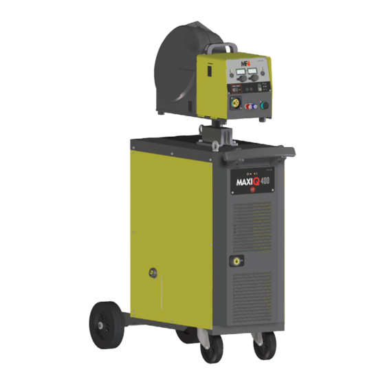
ENGLISH Description Introduction Description INVERTER GENERATOR FOR MIG-MAG WELDING A practical, robust metal structure combined with the latest Operating features generation inverter technology with digital welding control, characterise the multifunctional systems in the MAXIQ series. Technical data Innovative, technologically advanced, robust, and easy to use, Usage limits (IEC 60974-1) they can be used for very high quality MIG-MAG welding for all materials, reducing repeat work due to spray to a minimum,... -
Page 5: Technical Data
0,030 Ω MAXIQ 400 - 0,030 Ω MAXIQ 400w - 0,020 Ω MAXIQ 500 - 0,020 Ω MAXIQ 500w. at the interface point between the user’s supply and the public system. It is the responsibility of the installer or user of the equipment to ensure, by consultation with the distribution net-... -
Page 6: Ambient Conditions
The welding unit is characterized by the following classes: Ambient conditions • IP 23 S protection class indicates that the generator can be used in both interior and exterior environments. The manufacturer does not accept any responsibility for dam- • The “S” usage class indicates that the generator can be em- age that may result from the plant being used or stored in am- ployed in environments with a high risk of electrical shocks. -
Page 7: Usage Norms
Pos. 9 Quick positive pole connection on the connecting ca- Usage norms ble. Pos. 10 Connector for connecting the interconnection cable. CONTROL APPARATUS (Fig. A) Pos. 11 White LED: signals power supply presence. When it Pos. 1 Front panel. is switched on, the system is powered up and ready Pos. -
Page 8: Mig-Mag Welding
The delivery (blue coloured) and return (red coloured) wa- MIG-MAG welding ter tubes, used for cooling the torch of the welding machine, are part of the interconnection cable and should be con- To begin MIG-MAG welding, carry out the following tasks (with nected as follows: the machine switched off). - Page 9 2B - Connecting the cables - Welding with a 2) Connect up the earthing system cable to the rapid cou- pling marked by a + (positive) symbol and then the relevant NEGATIVE POLE TORCH (Fig. B2) ground clamps to the piece being welded or to its support in 1) Connect the generator - feeder connection cable using the an area free from rust, paint and grease.
-
Page 10: Aluminium Welding
4) Open the tap on the cylinder slowly and adjust the reduc- Optional er knob to obtain a pressure of about 1,3 to 1,7 bar, and then activate the gas test button and regulate the flow to NOTE: The digital control unit of the generator is fitted with a a value between 14 and 20 lit/min to suit the current used control recognition device which allows it to identify which de- for welding. -
Page 11: Meaning Of Graphic Symbols On Machine
Meaning of graphic symbols on machine Power supply switch Positive pole snap-in connector System for use in environments with in- Negative pole snap-in connector creased risk of electroshock Product suitable for free circulation in the Warning! European Community Before using the equipment you should carefully read the instructions included in Danger! high voltage this manual... -
Page 12: Wiring Diagram
Wiring diagram Key to the electrical diagram Colour key C-LINK Capacitor Orange-Black Interconnection cable connector Orange Power supply connector for the cooling system Sky Blue Connectors on PCB White Secondary diode Blue Fuse Grey F-EMC EMC filter Yellow Power supply switch Yellow-Green Secondary inductor Brown... - Page 13 2101EE08...
- Page 14 Operator’s manual READ CAREFULLY CEA COSTRUZIONI ELETTROMECCANICHE ANNETTONI S.p.A. C.so E. Filiberto, 27 - 23900 Lecco - Italy Tel. ++39.0341.22322 - Fax ++39.0341.422646 Cas. Post. (P.O.BOX) 205 E-mail: cea@ceaweld.com - web: www.ceaweld.com...
- Page 15 ENGLISH Introduction Introduction Description Thank you for buying our product. In order to get the best performance out of the plant and ensure Technical data the maximum lifespan of its parts, the use and maintenance instructions contained in this manual must be read and strictly Usage limits (IEC 60974-1) complied with, as well as the safety instructions contained Installation...
- Page 16 Persons fitted with pace-makers, hearing aids and similar Usage limits (IEC 60974-1) equipment must consult their doctor before going near a ma- chine in operation. The installation environment of the device The cooling device is sized for cooling by means of water cir- has to be in conformance with the protection degree of the culation in the welder in a continuous manner.
- Page 17 Start-up / drainage Before connecting the equipment to the utilities check the rating plate to make sure the voltage and frequency of the mains correspond and check that the main circuit breaker on the equipment is turnedto “O”. Upon the first usage following a period of extended inactivity of the device or in the case in which the electropump does not go under pressure (slight whistle), it is necessary to undertake drainage in order to eliminate all the air bubbles present within the hydraulic circuit.
- Page 18 Blue Blue...
- Page 19 Maintenance Wiring diagram WARNING: Prior to undertaking any kind of inspection within the machine, unplug the device from feed. • Periodically check the level of the cooling fluid. • Add fluid whenever it drops below the minimum level indi- cated. •...
- Page 20 Lista ricambi LEGGERE ATTENTAMENTE Spare parts list READ CAREFULLY CEA COSTRUZIONI ELETTROMECCANICHE ANNETTONI S.p.A. C.so E. Filiberto, 27 - 23900 Lecco - Italy Tel. ++39.0341.22322 - Fax ++39.0341.422646 Cas. Post. (P.O.BOX) 205 E-mail: cea@ceaweld.com - web: www.ceaweld.com...
- Page 21 IT Lista ricambi EN Spare parts list MAXIQ MAXIQ MAXIQ MAXIQ Pos. Descrizione Description 400w 500w 352389 352389 352389 352389 Pivot Pivot 447906 447906 447907 447907 Tastiera a membrana Membrane keyboard 439290 439290 439290 439290 Pannello rack Rack panel 438101 438101 438101 438101...
- Page 22 15 16 MAXIQ MAXIQ MAXIQ MAXIQ Pos. Descrizione Description 400w 500w 622020 622020 622020 622020 Golfare Eyebolt 447720 447720 447720 447720 Guarnizione Gasket 447226 447226 447226 447226 Ancoraggio bombola gas Gas cylinder holder 438720 438720 438720 438720 Manopola interruttore di linea Mains switch knob 468286 468286...
- Page 23 assembly MAXIQ MAXIQ MAXIQ MAXIQ Pos. Descrizione Description 400w 500w 435753 435753 435753 435753 Interruttore di linea Mains switch 427667 427667 427667 427667 Filtro EMC EMC Filter 481454 481454 481454 481454 Trasformatore ausiliario Auxiliary transformer 377213 377213 377213 377213 Scheda alimentazioni Power source PCB 413412 413412...
- Page 24 MAXIQ MAXIQ MAXIQ MAXIQ Pos. Descrizione Description 400w 500w 486377 486377 486383 486383 Ventilatore 455518 455518 455515 455515 Raddrizzatore secondario Secondary rectifier Termostato raddrizzatore 478788 478788 478790 478790 Secondary rectifier thermostat secondario 481954 481954 481954 481954 Trasformatore ad effetto di Hall Hall effect transformer...
- Page 26 MAXIQ MAXIQ MAXIQ MAXIQ Pos. Descrizione Description 400w 500w 418847 418847 Radiatore Radiator 460255 460255 Serbatoio Tank 466467 466467 Tappo serbatoio Tank cap Terminale per connettore maschio Terminal for 3x2 poles male 403783 403783 3x2 vie (lato raffreddamento) connector (water cooler side) Connettore maschio 3x2 vie 3x2 poles male connector 403779...
- Page 27 MAXIQ MAXIQ MAXIQ MAXIQ Pos. Descrizione Description 400w 500w 451740 451740 Portafusibile Fuse holder 429049 429049 Fusibile Fuse Cablaggio ausiliario per 413385 413385 Auxiliary wiring for water cooler impianto di raffreddamento 403625 403625 Attacco rapido blu Blue quick connection 403632 403632 Attacco rapido rosso Red quick connection...
- Page 28 4) O número de matrícula da própria máquina de soldar EXAMPLE EXEMPLO N. 2 pieces code n. 000000 - for MAXIQ 400 - 400 V - 50/60 N° 2 peças código n. 000000 - para o equipamento MAXIQ Hz - Serial number ............
- Page 29 3) Apparatets spenning og frekvens som finnes på merkeplaten for data på apparatet 4) Sveiseapparatets serienummer EKSEMPEL 2 stk. kode 000000 - for apparat MAXIQ 400 - 400 V - 50/60 Hz - Serienummer..........EL Πααγγελία των αανταλλακτικών Οταν ξητάτε ανταλλκτκά παρακαλείσθε να ημειώνετε καθαρά: 1) τον...
- Page 30 Operator’s manual READ CAREFULLY CEA COSTRUZIONI ELETTROMECCANICHE ANNETTONI S.p.A. C.so E. Filiberto, 27 - 23900 Lecco - Italy Tel. ++39.0341.22322 - Fax ++39.0341.422646 Cas. Post. (P.O.BOX) 205 e-mail: cea@ceaweld.com - web: www.ceaweld.com...
- Page 31 ENGLISH Technical data Introduction Description The general technical data of the system are summarized in ta- ble 1. Technical data Table 1 How to lift up the system Model MF4 - MF4w Opening the packaging Input voltage of wire feeder 24 DC Power output of feeder motor Installation and connections...
-
Page 32: Loading Wire
Installation and connections CONNECTION OF THE INTERCONNECTING CABLE BETWEEN WIRE FEEDER AND GENERATOR The extension between the generator and wire feeder consists of a power cable, a multipolar cable for auxiliary power supply and a gas hose which are to be connected to the rear of the wire feeder. •... -
Page 33: Before Welding
Before welding Replacing the motor control board • Before welding, check that the data on the power source plate Proceed as follows: correspond to the supply voltage and frequency. • Unscrew the 4 screws on the sides of the panel to loosen it. •... -
Page 34: Welding Defects
Welding defects Problem Cause Remedy The welder does not supply current • No power • Check that the power cable from the generator to the line and repair if necessary • Torch button does not work • Check that the torch switch gives consensus;... -
Page 35: Wiring Diagram
Wiring diagram 2101FE09... -
Page 36: Key To The Electrical Diagram
Key to the electrical diagram Colour key 17 pin connector for accessories / optional Orange-Black 17 pin connector for remote control connections Sky Blue Drive motor connector White Connectors on PCB Blue Torch connector Grey 24VDC solenoid valve Yellow Membrane keyboard Yellow-Green Ratio-motor Brown... - Page 37 Lista ricambi LEGGERE ATTENTAMENTE Spare parts list READ CAREFULLY CEA COSTRUZIONI ELETTROMECCANICHE ANNETTONI S.p.A. C.so E. Filiberto, 27 - 23900 Lecco - Italy Tel. ++39.0341.22322 - Fax ++39.0341.422646 Cas. Post. (P.O.BOX) 205 e-mail: cea@ceaweld.com - web: www.ceaweld.com...
-
Page 38: Pos
IT Lista ricambi EN Spare parts list Pos. MF4w Descrizione Description 447905 447905 Tastiera a membrana Membrane keyboard 438888 438888 Manopola encoder Encoder knob Connettore 17 poli per collegamento 419051 419051 17 Pole connector for accessories / optional accessori / optional 403933 403933 Attacco rapido blu... -
Page 39: Pos
Pos. MF4w Descrizione Description 420440 420440 Copribobina Spool cover 431329 431329 Piedino in gomma Rubber foot 404848 404848 Basamento Base 403935 403935 Attacco rapido maschio Male quick connection 403617 403617 Attacco rapido Quick connection Connettore 14 poli collegamento 14 Pole connector the interconnecting 453146 453146 cavo interconnessione... -
Page 40: Pos
optional Pos. MF4w Descrizione Description 235237 235237 Cavo di potenza Power cable 400000 400000 Adattatore Adaptor 444471 444471 Motoriduttore Drive motor 413379 413379 Cablaggio ausiliario Auxiliary wiring 485040 485040 Tubo gas Gas tube 425987 425987 Elettrovalvola Solenoide valve 377208 377208 Scheda Push Pull (opzionale) Push Pull pcb (option) -
Page 41: Pos
Pos. MF4w Descrizione Description Pag. 6 Pag. 6 Meccanismo di trascinamento Wire feed mechanism assembly 241848 241848 Mozzo bobina Spool holder 377207 377207 Scheda comando motore Motor control PCB 454150 454150 Encoder Encoder 406883 406883 Flangia di guida per pivot Guide flange for pivot 415380 415380... -
Page 42: Pos
IT Complessivo meccanismo di EN Complete entrainment mechanism with 4 rolls trascinamento a 4 rulli 16 15 14 20 21 Pos. Cod. Descrizione Description 307271 Base meccanismo di trascinamento Wire feed mechanism base 437075 Dispositivo di pressione rulli Pressure device 356963 Complessivo leva di pressione sinistra Pressure arm left complete... - Page 43 IT Rulli di trascinamento EN Drive mechanism Rullo inferiore Rullo superiore FILO Diametro filo TWIN kit (doppia cava) Ø37 mm (cava singola) Ø30 mm WIRE Wire diameter Lower roller Upper roller TWIN kit (double slot) Ø37 mm (single slot) Ø30 mm 0,6 ÷...
- Page 44 Operator’s manual READ CAREFULLY OPERATOR SOFTWARE (CONTROL PANEL) CEA COSTRUZIONI ELETTROMECCANICHE ANNETTONI S.p.A. C.so E. Filiberto, 27 - 23900 Lecco - Italy Tel. ++39.0341.22322 - Fax ++39.0341.422646 Cas. Post. (P.O.BOX) 205 E-mail: cea@ceaweld.com - web: www.ceaweld.com...
- Page 45 ENGLISH Introduction MIG-MAG 1A - MANUAL MIG MAG PROCESS SELECTION 1B - MIG MAG HYBRID SYNERGIC PROCESS Control panel SELECTION KEY AND KNOB COMMANDS 2 - WELDING MODE SELECTION DISPLAY AND LED INDICATIONS 3 - SPECIAL FUNCTIONS “Fx” SELECTION 4 - PRE-SETTING Switching on the welding machine and initial screen 5 - WELDING 6 - HOLD...
-
Page 46: Control Panel
Control panel KEY AND KNOB COMMANDS ■ ENCODER knob - A Allows adjustment of the welding wire speed. ■ ENCODER knob - V This is used to set and edit the PARAMETERS - V based on the corresponding LED switched on and the value highlighted on the DISPLAY PARAME- TERS - V display, required for correct functioning of the machine. -
Page 47: Display And Led Indications
DISPLAY AND LED INDICATIONS ■ PARAMETER DISPLAY screen - A This Display shows the values of the following pa- rameters (if active): • WELDING CURRENT ( ). • WIRE SPEED ( ■ PARAMETER DISPLAY screen - V This Display shows the values of the following pa- rameters (if active): •... -
Page 48: Switching On The Welding Machine And Initial Screen
Switching on the welding Loading of the wire machine and initial screen With the welder in operation, it is possible to load the wire inside the torch, following this simple procedure: At the switching on of the welder (turn the switch on the rear panel •... - Page 49 Table 1 *This string only appears if the cooling system is fitted. ** Change the PCB SETTINGS before the TORCH SETTINGS. Only with PCB present are you able to choose one of the 4 factory default PUSH PULL torches already configured or perform the calibration (CAL) of a different torch. If no board is present, the above operations are not allowed and the text “noboArd”...
-
Page 50: Special Functions "Fx
2) PROGRAM DEFAULT (dEF) Special functions “Fx” To access the SPECIAL FUNCTIONS “Fx” menu, hold the SPE- WARNING: If carried out, this operation resets the parame- CIAL FUNCTIONS “Fx” key (T5) down for at least 3 consecutive ters of the special functions Fx currently in use. seconds. -
Page 51: Menu Special Functions
Menu SPECIAL FUNCTIONS Enter the Fx menu following the usual procedure. Turn the ENCODER - A (E1) knob until SPC FnC is displayed. Press the Fx key (T5) again for at least 3 seconds and you will enter the menu. By turning the ENCODER - A (E1) knob the available functions will be shown on the two displays according to this sequence: FACTORY DEFAULT... -
Page 52: Safety Calibration Code (Scc)
SAFETY CALIBRATION CODE (SCC) TORCH CALIBRATION (PUSH PULL) • To calibrate a torch other than the standard torch already con- ATTENTION: This operation, if carryed on, optimizes the ef- figured, proceed as follows: ficiency of the welding circuit. 1) WARNING: Before beginning the procedure it is essential that the welding wire is already loaded in the PUSH PULL torch To set the length of the welding circuit (adjustable from 1 to 100 (see the relevant “WIRE LOADING”... -
Page 53: Delta Offset
• Rotate the ENCODER - A (E1) knob until display D1 reads brd. MOTOR CALIBRATION (Mot CAL) • Rotate the ENCODER-V (E2) knob until display D2 reads oFF - SinC 10 - SinC 150. ATTENTION: This procedure allows you to calibrate the wire speed. -
Page 54: Water Cooling Mode
WATER COOLING MODE ERROR LOG This configuration allows the operator to set cooling (only if avail- This allows the operator to know about the error states that have able), in the following ways: arisen on the welding plant. • ON DEMAND - In this case, cooling is managed in relation to 1) Rotate the ENCODER - A (E1) knob, until both the displays the welding done. -
Page 55: Diagnostics
DIAGNOSTICS TEST The information contained in this menu allows service personnel This configuration allows the operator to check that some func- to understand what is causing the system to malfunction. tions of some devices. 1) Rotate the ENCODER - A (E1) knob, until both the displays 1) Rotate the ENCODER - A (E1) knob, until both the displays (D1-D2) read diAGno. -
Page 56: Mig-Mag
MIG-MAG Start the welding machine by turning the switch on the rear pan- el to position I. 1A - MANUAL MIG MAG PROCESS SELECTION With the HYBRID SYNERGIC LED off, the MANUAL MIG MAG process is active. BLINK T ≥ 3 s To exit and confirm the choice, press and release the SET key (T2) and the LED L2 stops flashing and becomes steady, the panel is in HYBRID SYNERGIC mode. -
Page 57: Special Functions "Fx" Selection
3 - SPECIAL FUNCTIONS “Fx” SELECTION 4 - PRE-SETTING The SPECIAL FUNCTIONS “Fx” that are only available in the MIG- Before welding it is possible to set the following parameters: MAG manual welding process are shown below. For all the other explanations regarding this menu make reference to the relative paragraph. -
Page 58: Hold
6 - HOLD Error condition This function automatically starts itself at the conclusion of every welding operation and it is indicated to the operator by means of a This paragraph describes the error conditions that may arise on flashing light of the HOLD FUNCTION LED for a specific amount the welding machine, the codes and messages shown on both op- of time. - Page 59 Table 2 Error condition Error code Error description and possible diagnosis POWER LIMITATION This alarm appears if the power limit is exceeded. The alarm alternates with the standard display every 1.5 seconds, despite which the machine continues to weld, supplying limited power, but complying with the values shown on the data plate. THERMAL PROTECTION T°C The welding stops due to an excessively high temperature (thermostat activated).
- Page 60 CEA COSTRUZIONI ELETTROMECCANICHE ANNETTONI S.p.A. C.so E. Filiberto, 27 - 23900 LECCO - ITALY Cas. Post. (P.O. BOX) 205 Tel. +39 0341 22322 - Fax +39 0341 422646 cea@ceaweld.com www.ceaweld.com...
Need help?
Do you have a question about the MAXIQ 400 and is the answer not in the manual?
Questions and answers