Table of Contents
Advertisement
Available languages
Available languages
Quick Links
Manuale d'istruzioni
IT
Lista ricambi
Operator's manual
EN
Spare parts list
Manuel d'instructions
FR
Liste pièces de rechange
Bedienungsanleitung
DE
Ersatzteilliste
Manual de instrucciones
ES
Lista repuestos
Tel. ++39.0341.22322 - Fax ++39.0341.422646
e-mail: cea@ceaweld.com - web: www.ceaweld.com
C.so E. Filiberto, 27 - 23900 Lecco - Italy
Cas. Post. (P.O.BOX) 205
2
LEGGERE
ATTENTAMENTE
98-105
21
READ
CAREFULLY
98-105
38
LIRE
ATTENTIVEMENT
98-105
56
SORGFÄLTIG
LESEN
98-105
74
LEER
ATENTAMENTE
98-105
Advertisement
Chapters
Table of Contents

Subscribe to Our Youtube Channel
Related Manuals for CEA Digistar 250 Dual Pulsed


Summary of Contents for CEA Digistar 250 Dual Pulsed
- Page 1 Liste pièces de rechange 98-105 Bedienungsanleitung SORGFÄLTIG LESEN Ersatzteilliste 98-105 Manual de instrucciones LEER ATENTAMENTE Lista repuestos 98-105 C.so E. Filiberto, 27 - 23900 Lecco - Italy Tel. ++39.0341.22322 - Fax ++39.0341.422646 Cas. Post. (P.O.BOX) 205 e-mail: cea@ceaweld.com - web: www.ceaweld.com...
-
Page 2: Table Of Contents
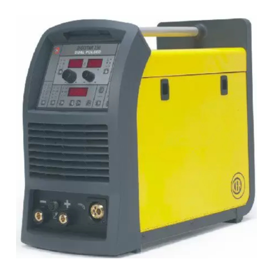
Saldatura dell'alluminio e nel settore automobilistico. Caratterizzati da dimensioni e peso ridotti, i generatori DIGISTAR 250 DUAL PULSED sono facil- Manutenzione mente trasportabili e consentono di avere disponibile in tutte le condizioni di lavoro un prodotto di altissimo livello tecnologico. -
Page 3: Dati Tecnici
• Eccezionali caratteristiche di saldatura in MIG/MAG, MIG pul- Tabella 1 sato e MIG doppio pulsato con tutti i materiali e diversi tipi di DIGISTAR 250 gas in assenza di spruzzi; Modello • Elevate caratteristiche di saldatura MMA e TIG con innesco DUAL PULSED tipo "Lift";... - Page 4 I portatori di pace-maker, di protesi auricolari e di apparecchia- Questo impianto è raffreddato mediante circolazione forzata di ture similari devono consultare il proprio medico prima di avvici- aria e deve quindi essere disposto in modo che l’aria possa es- narsi all’impianto in funzione.
- Page 5 mi dovuti alla maggiore resistenza e induttanza dei cavi che Saldatura MIG-MAG / MIG PULSATO/ MIG DOPPIO possono causare difetti di saldatura. Per evitare questi incon- PULSATO venienti seguire le seguenti prescrizioni: Per iniziare a saldare in MIG-MAG eseguire i collegamenti indi- - adottare cavi di massa di sezione adeguata;...
-
Page 6: Caricamento Del Filo
Caricamento del filo Montaggio rulli di trascinamento per alluminio • Infilare il rocchetto (Ø 300 mm MAX) sull’apposito supporto in modo tale che il filo si svolga in senso orario e centrando il riferimento sporgente del supporto con il rispettivo foro nella SMONTAGGIO RULLI ESISTENTI (fig. -
Page 7: Apparecchi Di Comando E Controllo
Apparecchi di comando e controllo Pos. 1 Attacco rapido polarità negativa Pos. 5 Interruttore di linea. Nella posizione "O" la saldatrice è spenta. Pos. 2 Connettore per comandi ausiliari saldatura Pos. 6 Connettore per l’alimentazione impianto di raffreddamen- Pos. 3 Attacco rapido polarità positiva to HR26 Pos. -
Page 8: Pannello Di Controllo
Pannello di controllo COMANDI A PULSANTE Pulsante SELEZIONE PARAMETRI - A Pulsante MODO DI SALDATURA Permette la selezione dei seguenti parametri (se attivi) e ad ogni Permette la selezione di 5 modi di saldatura: pressione del pulsante la macchina passa a selezionare il suc- •... - Page 9 2) Rilasciando il pulsante torcia la corrente si porta al valore di Pulsante RUN/MEM CORRENTE FINALE DI CRATERE (CEC) con una penden- A questo pulsante vengono associate due funzioni: za definita dal parametro SLOPE (SLO). • Funzione RUN utilizzata per visualizzare le caratteristiche (ma- In seguito la corrente rimane al valore di CORRENTE FINA- teriale, diametro del filo, tipo di gas ecc.) dei programmi forniti LE DI CRATERE (CEC) per un tempo definito dal parametro...
- Page 10 COMANDI A MANOPOLA Manopola ENCODER 1 Con questo encoder si possono modificare i valori dei parametri (se attivi) visualizzati sul display VISUALIZ- ZAZIONE PARAMETRI - A. Manopola ENCODER 2 Con questo encoder si possono modificare i valori dei parametri (se attivi) visualizzati sul display VISUALIZ- ZAZIONE PARAMETRI - V.
- Page 11 Le 5 modalità di saldatura sono indicate quando i led sono attivi Display VISUALIZZAZIONE PARAMETRI - A nel seguente modo: Questo display visualizza le seguenti funzioni (se attive): • La CORRENTE DI SALDATURA sia preimpostata (solo in tipologia SINERGICA) che reale; Modo di saldatura selezionato: 2T •...
-
Page 12: Visualizzazione Della Versione Del Software Installato
La corrente da impiegare dipende dalle La DIGISTAR 250 DUAL PULSED è dotata di un controllo digi- posizioni di saldatura, dal tipo di giunto e varia in modo crescen- tale con a bordo un software definito in fabbrica. - Page 13 - può variare da 10 a 40V). Il parametro visualizzato dai display Il generatore DIGISTAR 250 DUAL PULSED permette l'inseri- non varia passando dalla fase di preimpostazione a quella di sal- mento di 100 programmi, forniti dal costruttore, validi per ogni datura e viceversa.
-
Page 14: Creazione E Memorizzazione Di Nuovi Punti Automatici Di Saldatura
9) SLOPE - Pendenza della corrente per passare dal livello di Tipologia di lavoro AUTOMATICA "corrente iniziale di cratere" al livello di corrente di saldatura Si accede a questa modalità di saldatura premendo il pulsante e per arrivare da quest'ultimo livello al livello di "corrente fina- PROCESSO DI SALDATURA posizionandosi su MIG-MAG le di cratere"... -
Page 15: Richiamare I Punti Automatici Precedentemente Memorizzati
CONCETTO DI “SEQUENZA DI PUNTI AUTOMATICI Richiamare i punti automatici DI SALDATURA” precedentemente memorizzati Si definisce “sequenza di punti automatici di saldatura” il rag- gruppamento di un certo numero di punti automatici di saldatura salvati dall’utente. Il raggruppamento viene delimitato lasciando un punto automatico di saldatura vuoto all’inizio del raggruppa- Per richiamare i punti di saldatura precedentemente memorizzati mento e uno vuoto alla fine. -
Page 16: Reset Delle Impostazioni
• PASSWORD (scritta visualizzata sul display PAS) • LIVELLI DI BLOCCO (scritta visualizzata sul display BLL) DIGISTAR 250 DUAL PULSED I valori selezionabili attraverso la manopola ENCODER 2 e visualizzabili sul relativo display dVPV sono: Per mantenere il corretto funzionamento della macchina proce- •... -
Page 17: Comandi A Distanza Ed Accessori
Procedura di smontaggio e montaggio coperchio Comandi a distanza ed accessori I generatori DIGISTAR 250 DUAL PULSED possono essere equi- paggiati con diversi comandi a distanza ed accessori quali: Torcia up/down raffreddata ad aria e/o ad acqua La torcia up/down in tipologia di lavoro SINERGICA (SYN) e MA- NUALE (MAN) sostituisce in maniera completa l'ENCODER 1 pre- sente sul pannello di controllo del generatore. -
Page 18: Condizioni Di Errore
DESCRIZIONE ERRORE CODICE ERRORE File "CFG" (parametri di macchina) assente File "CUI" (parametri utente) assente File "CEA" (PID non di programma) assente File "CAL" (calibrazione macchina) assente Incongruenza di configurazione Curve processo di saldatura MIG/MAG assenti Curve processo di saldatura MIG PULSATO assenti... - Page 19 In questo paragrafo sono descritte le condizioni di errore re riscontrato (o del primo errore riscontrato nel caso di errori riscontrabili sulla saldatrice e per visualizzarli vengono utilizzati i multipli). tre display presenti sull'interfaccia operatore (fig. G): La tabella 6 riporta i possibili messaggi di errore che possono •...
-
Page 21: Introduction
The spatter-free welding feature minimises reprocessing work. Innovative, sturdy Welding sequence and easy to use, DIGISTAR 250 DUAL PULSED power sources are a perfect solution for all applications requiring high precision Resetting and repeatability of results, thus making them particularly suit-... -
Page 22: Technical Data
• User friendly and easy-to-use selection and recalling of the Usage limits (IEC 60974-1) parameters and welding programs; • Exclusive SWS "Smart Welding Stop" system at the end of The use of a welder is typically discontinuous, in that it is made TIG welding. - Page 23 CONNECTION OF THE WELDING CABLES TIG welding Connect up as shown in fig. B to start welding in TIG, more spe- cifically (with machine switched off): Electrode welding (MMA) • Connect up the gas tube, coming from its rapid coupling on the torch with TIG welding valve, to the gas cylinder and open With the machine disconnected from the it.
-
Page 24: Loading Wire
CONNECTION OF THE WELDER TO THE ELECTRICAL SUPPLY Connection of the machine to the user line (electrical cur- rent) must be performed by qualified personnel. Before connecting the welder to the electrical supply, check that the machine’s plate rating corresponds to the supply voltage and frequency and that the line switch of the welder is in the "O"... -
Page 25: Command And Control Units
ALUMINIUM ROLL KIT ASSEMBLY (fig. F) Insert the idle roller and spacer supplied in the kit into the gear housing (see figure to right) and secure the assembly to the arm with the lock pin (1). Remove the lock screw (position 3) and replace the 2 rollers with the ones supplied in the kit. -
Page 26: Control Panel
Control panel KEY CONTROLS A- PARAMETERS SELECTION Key WELDING MODE SELECTION Key Used to select the parameters given below (if activated) and the Used to select 5 welding modes: machine will go on to selecting the next parameter every time •... - Page 27 2) When you let go of the torch button, the current changes to RUN/MEM Key the FINAL CRATER CURRENT (CEC) value with a slope de- Two functions are associated with this key: fined by the SLOPE (SLO) parameter. • RUN function used for displaying operating details (materials, Subsequently, the current remains at the FINAL CRATER diameter of wire, type of gas, etc.) of programmes supplied by CURRENT (CEC) for a period of time defined by the FINAL...
- Page 28 KNOB CONTROLS ENCODER 1 Knob This encoder is used to change values of parameters (if active) on the A- PARAMETERS Display. ENCODER 2 Knob This encoder is used to change the values of param- eters (if active) on the V- PARAMETERS Display. DISPLAY AND LED INFORMATION A - PARAMETERS SELECTION Led WELDING MODE Led...
- Page 29 The 5 welding methods are indicated, when the LEDs are active, A - PARAMETERS Display in the following manner: This display reads the following functions (if activated): • WELDING CURRENT both pre-set (in SYNERGIC mode only) and actual; Selected welding method: 2T •...
-
Page 30: Viewing Installed Software Versions
A fairly approximate indication of the average current to use in Viewing installed software versions the welding of electrodes for ordinary steel is given by the follow- ing formula: The DIGISTAR 250 PULSED has a digital control with software on board produced in the factory. This software is subject to con- I = 50 x (Øe –... - Page 31 The pre-set readings of the welding current (adjustable with Connect up the welding cables following description given in the ENCODER 1 knob) and open-circuit voltage (not adjust- paragraph "Connecting the welding - MIG-MAG, MIG PULSED able) will be displayed on the A- PARAMETERS Display (abbrevi- or MIG DUAL PULSED welding cables (fig.
-
Page 32: Create And Memorize New Automatic Welding Spots
12) SPOT WELD TIME — Time needed for spot-welding (after Special functions pressing the torch key) after which the arc automatically Just press the SPECIAL FUNCTIONS key to enter these param- switches off (SPt - from 1 to 20 seconds with a 0.1 seconds eters. -
Page 33: Copy And Change Automatic Welding Spots
MEMORIZING A WELDING SEQUENCE Copy and change automatic To set a welding sequence, you must: 1) Check that you have a free point before the first automatic welding spots point (before position 1 and after position 99 there are always two free automatic welding points that mark off the sequence. -
Page 34: Resetting
After setting the shutdown levels and the password (relevant value LIMITS TO THE USE OF SEQUENCES and code must be entered the first time by the user) just press The use of sequences with the possibility of passing from one the SPECIAL FUNCTIONS key once more to exit from the menu automatic welding point to another while the welding is active is and have the machine ready again for welding. -
Page 35: Remote Controls And Accessories
SPARE PARTS Procedure for cover assembly and Original spare parts have been specially designed for our equip- ment. The use of non-original spare parts may cause variations disassembly in performance or reduce the foreseen level of safety. We decline all responsibility for the use of non-original spare parts. Remote controls and accessories DIGISTAR 250 PULSED generators may be fitted out with vari- ous remote control systems and accessories such as:... -
Page 36: Error Conditions
Display Display Display File "CFG" (machine parameters) none File "CUI" (user parameters) none File "CEA" (un-programmed PID ) none File "CAL" (machine calibration) none Incongruent configuration No MIG/MAG welding process curves No MIG PULSED welding process curves No MIG DUAL PULSED welding process... - Page 37 Error conditions found in the welder are described in this para- of communication with the peripherals, a change has been made graph and the three displays on the operator's interface (fig. G) to the leds located on the “digital card cpu front panel” (see table used to view them: 7 and fig.
-
Page 38: Introduction
éclaboussures rendent néces- Séquences de soudure saires. Novatrices, robustes et faciles à utiliser, les installations de soudage DIGISTAR 250 DUAL PULSED sont la solution idéale Réinitialisation des configurations pour les travaux répétitifs de précision ; ces générateurs sont conçus pour tous les domaines industriels et professionnels, en... -
Page 39: Donnees Techniques
• Caractéristique de soudage sans projection exceptionnelle Tableau 1 aussi bien en MIG/MAG qu'en MIG Pulse avec tout type de DIGISTAR 250 gaz; Modele • Haute performance de soudage en MMA et TIG avec système DUAL PULSED d'amorçage "lift arc"; Alimentation triphasée 50/60Hz •... -
Page 40: Installation Et Branchements
• Classe de protection IP 23 indique que le générateur peut être Installation et branchements utilisé aussi bien à l’intérieur qu’à l’extérieur; • Classe d’utilisation "S" signifie que le générateur peut être uti- Le lieu de mise en place de l'installation doit être choisi avec lisé... - Page 41 élevées des câbles, susceptibles de causer des défauts de sou- Soudage MIG-MAG / MIG PULSE/ MIG DUAL dage. Pour éviter ces inconvénients, conformez-vous à ces PULSE prescriptions: Pour commencer à souder en MIG-MAG, effectuez les connexions • choisissez des câbles de masse de section adéquate; illustrées par la Fig.
-
Page 42: Chargement Du Fil
Chargement du fil Montage des rouleaux de transport pour l'aluminium • Enfilez la bobine (Ø 300 mm MAX) sur le support de façon à ce que le fil se déroule en sens horaire en faisant coïncider le point de repère du support en face du trou de la bobine. •... -
Page 43: Appareils De Commande Et De Controle
Appareils de commande et de controle Pos. 1 Raccord rapide polarité négative Pos. 4 Connecteur centralisé torche Pos. 2 Connecteur pour commandes auxiliaires de soudage Pos. 5 Interrupteur de ligne. En position "O", la soudeuse est éteinte Pos. 3 Raccord rapide polarité positive Pos. -
Page 44: Tableau De Contrôle
Tableau de contrôle TOUCHES DE COMMANDE • 2T CRATÈRE Bouton pour la SELECTION DES PARAMETRES - A Permettent de sélectionner les paramètres suivants (s'ils sont actifs) et à chaque pression de la touche la machine passe à la S L O [ A / s ] sélection du paramètre suivant (fonction valide pour toutes les C S C [ % ] 1 0 0 %... - Page 45 • 4T CRATÈRE Bouton pour le TEST GAZ L'électrovanne est activée et le gaz commence à sortir quand cette touche est pressée puis relâchée. La sortie de gaz s’inter- S L O [ A / s ] C S C [ % ] rompt, automatiquement, après 30 secondes ou, en mode ma- 1 0 0 % nuel, en appuyant sur la touche et en la relâchant.
- Page 46 POIGNÉE DE COMMANDE Molette de règlage ENCODER 1 Cet encodeur permet de modifier les valeurs des para- mètres (s'ils sont actifs) affichés sur la page VISUALI- SATION PARAMÈTRES - A. Molette de règlage ENCODER 2 Cet encodeur permet de modifier les valeurs des para- mètres (s'ils sont actifs) affichés sur la page VISUALI- SATION PARAMÈTRES - V.
- Page 47 Les 5 modes de soudure sont indiqués, quand les LEDs sont Display POUR LA VISUALISATION DES actives, de la manière suivante: PARAMETRES - A Cette affichage montre les fonctions suivantes (si elles sont acti- ves): Mode de soudure sélectionné: 2T •...
-
Page 48: Affichage De La Version De Logiciel Installée
• Moyen pour les soudures au-dessus de la tête, Affichage de la version de logiciel • Bas pour la soudure verticale descendante et pour unir des pièces de petites dimensions préchauffées. installée Une indication, très approximative, du courant moyen à utiliser pour la soudure d’électrodes en acier normal est fournie par la Le DIGITECH 250 DUAL PULSED dispose d'une commande formule suivante:... - Page 49 Pendant ce procédé grâce au système novateur d'amorce Lift à Avant d'effectuer le soudage l'affichage VISUALISATION PARA- contrôle thermique (TCDS), les allumages s'effectuent de façon MÈTRES - A (abrégé dVPA) montre les valeurs prédéfinies pour précise et rapide, en réduisant au minimum les inclusions de l'épaisseur de la pièce , l'intensité...
-
Page 50: Creation Et Memorisation Nouveaux Points
11) FREQUENCE DUAL PULSE - Définit la fréquence de la dou- Fonctions speciales ble pulsation (FdP - de 0,5 à 5 Hz avec intervalle de réglage Pour accéder à ces paramètres il suffit d'appuyer sur la touche de 0,1 Hz); FONCTIONS SPÉCIALES: Nous vous décrivons brièvement ci- 12) TEMPS DE POINTAGE - Durée pendant laquelle s'effectue après les paramètres susceptibles d'être modifiés et sur le ta-... -
Page 51: Copier Et Modifier Les Points Automatiques
MÉMORISER UNE SÉQUENCE DE SOUDURE Copier et modifier les points Pour établir une séquence de soudure, il faut: 1) vérifier de bien avoir un point libre avant le premier point auto- automatiques de soudure matique (On suppose implicitement qu'avant la position 1 et après la position 99, il y ait deux points automatiques de sou- Après avoir rappelé... -
Page 52: Réinitialisation Des Configurations
• 2 = VERROUILLAGE DE NIVEAU 2 actif CONDITIONS POUR L'UTILISATION DES Il est impossible de modifier certains paramètres de soudage. SEQUENCES • 3 = VERROUILLAGE DE NIVEAU 3 actif L'utilisation des séquences, avec la possibilité de passer d'un En mode SYNERGIE et MANUEL il est impossible de modifier point automatique de soudure à... -
Page 53: Commandes À Distance Et Accessoires
TORCHE Releve des eventuels inconvenients et La torche est soumise à des températures élevées et de plus elle est sollicitée par des tractions et des torsions. Il est recommandé leur elimination donc d’éviter des pliages nets du câble et de ne pas utiliser la torche comme câble de traînage pour déplacer la soudeuse. -
Page 54: Conditions D'erreur
DESCRIPTION ERREUR CODE ERREUR Fichier "CFG" (paramètres de la machine) absent Fichier "CUI" (paramètres utilisateur) absent Fichier "CEA" (PID non de programme) absent Fichier "CAL" (étalonnage machine) absent Incohérence de configuration Courbes procédé de soudage MIG/MAG absentes Courbes procédé de soudage MIG PULSE absentes Courbes procédé... - Page 55 Ce paragraphe décrit les conditions d'erreur possibles sur la sou- différentes erreurs. deuse qui sont visualisés sur les trois affichages de l'interface En outre, pour faciliter lediagnostic de problèmes éventuels de opérateur (fig. G): communication avec les périphériques, le comportement des led •...
-
Page 56: Vorwort
Minimum reduziert. Innovativ, robust und einfach im Gebrauch stellen die Schweiß- Reset der Einstellungen anlagen DIGISTAR 250 DUAL PULSED die ideale Lösung für all diejenigen Arbeiten dar, bei denen hohe Präzision und Wieder- Einschränkung für die Änderung der Parameter holbarkeit der Ergebnisse gefordert werden, was diese Genera- toren besonders für den Einsatz in allen Industrie- und Profi-... -
Page 57: Technische Eigenschaften
tes und vermeidet so die Bildung des klassischen unerwünsch- Tabelle 1 ten „Kügelchens“. Dadurch wird eine korrekte Neuzündung des DIGISTAR 250 Bogens gewährleistet; Modelle • Außergewöhnliche spritzerfreie Lichtbogencharakteristik im DUAL PULSED MIG/MAG and Pulsed ARC-MIG Verfahren mit jedem Material Drehstromversorgung 50/60 Hz und Gas;... - Page 58 Träger von Herzschrittmachern, Hörgeräten oder ähnlichen Ein- ANSCHLUSS DER SCHWEISSKABEL richtungen sollten ihren Arzt befragen, bevor sie sich der in Be- trieb befindlichen Anlage nähern. Der Standort der Anlage muß Elektrodenschweissen (MMA) dem Schutzgrad des Gehäuses entsprechen. Bei ausgeschaltetem Strom die Schweisskabel mit den Ausgangs- Die Schweißeinheit zeichnet sich durch folgende Klassen aus: klemmen (Pluspol - Minuspol) der Schweissmaschine verbinden •...
- Page 59 kabeln verursacht Spannungsabfälle und einige Probleme, die MIG MAG/PULSIERTES MIG MAG/MIG auf den größeren Widerstand und die Induktivität der Kabel DOPPELPULS-Schweissen zurückführen sind und zu Schweißfehlern führen können. Zur Für den Beginn des MIG-MAG-Schweißverfahrens die in der Abb. Vermeidung dieser Mängel folgende Vorschriften beachten: C angegebenen Anschlüsse vornehmen, und zwar (bei ausge- •...
-
Page 60: Einlegen Des Drahts
Einlegen des Drahts Einbau der Mitnahmerollen für Aluminium • Die Rolle (Ø 300 mm MAX) so auf die entsprechende Halte- rung setzen, dass der Draht im Uhrzeigersinn angewickelt wird und die vorstehende Halterungsreferenz mit dem entsprechen- den Loch in der Rolle ausgerichtet ist. AUSBAU DER BESTEHENDEN ROLLEN (Abb. -
Page 61: Steuer Und Kontrolleinrichtungen
Steuer und kontrolleinrichtungen Pos. 1 Schnellanschluss Minuspol Pos. 4 Zentralanschluß für Brenner Pos. 2 Steckverbinder für die Zusatzsteuerungen für das Pos. 5 Leitungsschalter. In Position "O" ist das Schweißgerät Schweißen ausgeschaltet Pos. 3 Schnellanschluss Pluspol Pos. 6 Steckverbinder zur Speisung der HR26 Kühlanlage... -
Page 62: Steuerpaneel
Steuerpaneel TASTENSTEUERUNGEN • 2T-KRATER A - PARAMENTER Auswahldrucktaste Erlaubt die Wahl folgender Parameter (wenn aktiv) und bei jedem Tastendruck geht die Maschine zur Wahl des anschließenden Pa- S L O [ A / s ] C S C [ % ] rameters über (Funktion für alle aufgelisteten Tasten gültig), wo- 1 0 0 % bei folgende Ordnung eingehalten wird:... - Page 63 • 4T-KRATER GASTEST Drucktaste Das Magnetventil wird aktiviert und das Gas beginnt auszuströ- men, wenn diese Taste gedrückt und losgelassen wird. Der Gas- S L O [ A / s ] C S C [ % ] 1 0 0 % austritt endet automatisch nach 30 Sekunden oder manuell, wenn die Taste gedrückt und losgelassen wird.
- Page 64 DREHKNOPFSTEUERUNGEN ENCODER 1 Knopf Mit diesem Codierer kann man die Werte der Parame- ter (wenn aktiv) ändern, die auf dem Display PARAME- TER-ANZEIGE - A angezeigt werden. ENCODER 2 Knopf Mit diesem Codierer kann man die Werte der Parame- ter (wenn aktiv) ändern, die auf dem Display PARA- METER-ANZEIGE - V angezeigt werden.
- Page 65 Die 5 Schweißarten werden angezeigt, wenn die LEDs folgen- A - PARAMETER Anzeige dermaßen aktiv sind: Dieses Display zeigt folgende Funktionen (wenn aktiv) an: • Sowohl den (nur in der Typologie SYNERGETISCH) vorgege- benen als auch den realen SCHWEISS-STROM; Gewählte Schweißart: 2T •...
-
Page 66: Anzeige Der Installierten Software-Version
bestimmen den einzusetzenden Strom. Die einzustellende Strom- Anzeige der installierten Software- stärke ändert inner-halb des Regelbereichs der Tabelle 3 und wird so bestimmt: Version • hoch beim Flachschweissen, Flach-Stirnschweissen und Ver- tikal-Aufwärtsschweissen; Der DIGITECH 250 DUAL PULSED ist mit einer Digital-Steue- •... - Page 67 Bevor die Schweißung ausgeführt wird, werden auf den Displays PROGRAMMANZEIGE (abgekürzt dVP) angezeigt werden. PARAMETERANZEIGE - A (abgekürzt dVPA) und PARAMETER- Die Schweißkabel nach der Beschreibung in dem Paragraphen ANZEIGE - V (abgekürzt dVPV) die voreingestellten Werte für "Anschluss der Schweißkabel - MIG-MAG-Schweißung, Schweißstrom (durch den Drehknopf ENCODER 1 veränder- GEPULSTE MIG-Schweißung oder GEPULSTE DOPPELMIG-...
-
Page 68: Erstellung Und Speicherung Neuer
Außerdem erlaubt diese Arbeitstypologie die Schaffung und Spei- 8) ZEIT DES ENDSTROMS - Zeit, während der der Strom auf cherung (siehe entsprechende Paragraphen) von Schweißeins- dem Kraterendwert bleibt (aktiv nur im 2T-KRATER-Betrieb) tellungen ( -Punkten), die dann in der AUTOMATISCHEN (ECt - von 0 bis 5 Sek. -
Page 69: Die Vorher Gespeicherten Automatischen
DAS KONZEPT DER “SEQUENZ AUTOMATISCHER Die vorher gespeicherten SCHWEISSSTELLEN” automatischen punkte abrufen Als “Sequenz automatischer Schweißstellen” wird die Gruppie- rung einer bestimmten, vom Benutzer abgespeicherten Anzahl automatischer Schweißstellen definiert. Die Gruppierung wird Zum Abrufen der vorher gespeicherten Schweißpunkte muss man dadurch begrenzt, dass eine automatische Schweißstelle am zur AUTOMATISCHEN Arbeitstypologie gehen und dann die Ta- Anfang der Gruppierung und eine an deren Ende leer gelassen... -
Page 70: Reset Der Einstellungen
Der Übergang von einer automatischen Stelle zur anderen wird • 0 = FEHLENDER STILLSTAND oder MASCHINENFREIGABE ausgeführt, indem die mittels eine Stromrampe gespeicherten Man hat keinen Maschinenstillstand und außerdem erlaubt dies, Strömungen miteinander verbunden werden. Die Steilheit ist in- sie freizugeben, wenn sie vorher blockiert wurde (nach vorhe- nerhalb der Spezialfunktionen der automatischen Empfänger- riger Eingabe des richtigen Kennwortes). -
Page 71: Fernsteuerungen Und Zubehör
Luftstrahl nicht direkt belüften, um keine Schaden anzurich- Fehlersuche und fehlerbeseitigung ten. • Periodische Inspektion zur Ermittlung von abgenutzten Kabeln Die meisten Störungen treten an der Zuleitung ein. Gegebenen- oder von lockeren Verbindungen, die Überhitzungen verursa- falls so vorgehen wie folgt: chen. -
Page 72: Fehlerbedingungen
Display DIAGNOSE FEHLER FEHLERBESCHREIBUNG FEHLERCODE Datei "CFG" (Maschinenparameter) fehlt Datei "CUI" (Benutzerparameter) fehlt Datei "CEA" (PID nicht im Programm) fehlt Datei "CAL" (Maschinenkalibrierung) fehlt Inkongruenz der Konfiguration Kurven MIG-MAG-Schweißverfahren fehlen Kurven GEPULSTES MIG-Schweißverfahren fehlen Kurven GEPULSTES DOPPELMIG-Schweiß- verfahren fehlen Kontrollfehler des gespeicherten Dateisystems FLASH Alarm OVER VOLTAGE. - Page 73 • Display FEHLERCODE (abgekürzt mit dCE): auf diesem Dis- den, wurde außer der Anzeige mittels Led DL1 der Zugang zu play erscheint die blinkende Schrift des Codes (4 Ziffern) des den Schweißvorgängen MIG/MAG, MIG PULSIERT und MIG festgestellten Fehlers (oder des ersten festgestellten Fehlers DOPPELT PULSIERT verhindert.
-
Page 74: Premisa
Innovadoras, robustas y fáciles de utilizar, las ins- Limitación de la modificación de los parámetros talaciones de soldadura DIGISTAR 250 DUAL PULSED repre- sentan la solución ideal para todos los trabajos que requieran Función "ENERGY SAVING"... -
Page 75: Datos Técnicos
• Control del BURN BACK. Al final de la soldadura, en todas las Tabla 1 condiciones y con cualquier material, el control digital asegura DIGISTAR 250 un corte perfecto del hilo, evitando la formación de la clásica e Modelo indeseada "bolita", garantizando un correcto reencendido del DUAL PULSED arco;... -
Page 76: Instalación Y Conexiónes
La unidad de soldadura está caracterizada por las siguientes cla- Instalación y conexiónes ses: • Clase de protección IP 23 indica que el generador puede ser El lugar de instalación de la soldadora debe ser elegido cuidado- usado tanto en ambientes internos como al aire libre; samente de manera tal de asegurar un servicio satisfactorio y •... - Page 77 Soldadura MIG-MAG / MIG PULSADO / MIG DOBLE PULSADO Para comenzar a soldar en MIG-MAG efectuar las conexiones inductancia de los cables que pueden causar defectos de sol- indicadas en la Fig. C y más precisamente (con máquina apaga- dadura. Para evitar estos inconvenientes seguir las siguientes da): prescripciones: •...
-
Page 78: Carga Del Hilo
Carga del hilo Montaje rodillos de arrastre para aluminio • Introduzca el carrete (Ø 300 mm MAX) en el específico soporte de forma que el cordón se enrolle en el sentido de las agujas del reloj y centrando la referencia que sobresale del soporte con el respectivo orificio en el carrete. -
Page 79: Aparatos De Mando Y Control
Aparatos de mando y control Pos. 1 Acoplamiento rápido polaridad negativa Pos. 5 Interruptor de línea. En la posición "0" la soldadora está apagada Pos. 2 Conector para mandos auxiliares soldadura Pos. 6 Conector para la alimentación del sistema de enfriamien- Pos. -
Page 80: Panel De Control
Panel de control MANDOS DE PULSANTE • 2T CRÁTER Pulsador SELECCIÓN PARAMETROS - A Permite la selección de los siguientes parámetros (si activados) y en cada presión del pulsador la máquina pasa a seleccionar el S L O [ A / s ] C S C [ % ] 1 0 0 % sucesivo parámetro (función válida para todos los pulsadores... - Page 81 • 4T CRÁTER Pulsador PRUEBA GAS Se activa la electroválvula y el gas comienza a salir cuando se aprieta y se suelta este pulsador. El escape de gas termina, de S L O [ A / s ] C S C [ % ] 1 0 0 % manera automática, después de 30 segundos o bien, en forma manual, presionando y soltando el pulsador.
- Page 82 MANDOS DE BOTÓN Mando ENCODER 1 Con éste encoder se pueden modificar los valores de los parámetros (si activados) visualizados en el dis- play VISUALIZACIÓN PARÁMETROS - A. Mando ENCODER 2 Con éste encoder se pueden modificar los valores de los parámetros (si activados) visualizados en el dis- play VISUALIZACIÓN PARÁMETROS - V.
- Page 83 Las 5 modalidades de soldadura se indican cuando los led se Display VISUALIZACION PARAMETROS - A encuentran activos de la siguiente forma: Este display visualiza las siguientes funciones (si activadas): • La CORRIENTE DE SOLDADURA tanto preprogramada (úni- camente en tipología SINÉRGICA) como real; Seleccionado modo de soldadura: 2T •...
-
Page 84: Visualización De La Versión Del Software Instalado
ción del espesor y de las dimensiones de la pieza. El valor de Visualización de la versión del intensidad de corriente que se debe utilizar para los diferentes tipos de soldadura, dentro del campo de regulación indicado en software instalado la tabla 3 es: •... - Page 85 Antes de efectuar la soldadura en los display VISUALIZACIÓN Conectar los cables de soldadura de acuerdo con lo descrito en PARÁMETROS - A (abreviado dVPA) y VISUALIZACIÓN el párrafo "Conexión de los cables de soldadura - soldadura MIG- PARÁMETROS - V (abreviado dVPV) se visualizan los valores de MAG, MIG PULSADO o MIG DOBLE PULSADO (Fig.
-
Page 86: Creación Y Memorización De Nuevos Puntos Automáticos De Soldadura
8) TIEMPO DE LA CORRIENTE FINAL - Tiempo durante el cual Tipología AUTOMATICA de trabajo la corriente permanece con el valor final de cráter (activo úni- Se accede a esta modalidad de soldadura presionando el pulsa- camente en modalidad 2T CRÁTER) (ECt - de 0 a 5 seg. con dor PROCESO DE SOLDADURA colocándose sobre MIG-MAG intervalo de regulación de 0,1 segundos). -
Page 87: Hacer Referencia A Los Puntos Automáticos Anteriormente Memorizados
Hacer referencia a los puntos Secuencias de soldadura automáticos anteriormente Se ha introducido la posibilidad de efectuar trabajos de soldadu- ra recurriendo a la utilización en secuencia de puntos automáti- memorizados cos de soldadura anteriormente memorizados por el usuario. También se gestiona el cambio del punto automático con solda- Para solicitar los puntos de soldadura precedentemente memo- dura activa, con la condición que se utilice una antorcha de tipo rizados, es necesario acceder a la tipología AUTOMÁTICA de... -
Page 88: Reset De Las Programaciones
Cuando la soldadura está activa, pulsando los botones derecho Los valores seleccionables mediante el mando ENCODER 2 y (+) e izquierdo (-) en la antorcha, es posible pasar de un punto visualizables en el relativo display dVPV son: automático de soldadura al anterior o sucesivo en el interior de •... -
Page 89: Mandos A Distancia Y Accesorios
portarse consecuentemente. Para hacer que el dispositivo de DIGITECH 250 DUAL PULSED autorreconocimiento funcione correctamente, es necesario (con Para mantener el correcto funcionamiento de la máquina proce- la máquina apagada) conectar al relativo conector el accesorio der tal como descrito: que hay que utilizar y a continuación encender la soldadora con •... -
Page 90: Condiciones De Error
DESCRIPCIÓN ERROR CÓDIGO ERROR Filas "CFG" (parámetros de máquina) ausente Filas "CUI" (parámetros usuario) ausente Filas "CEA" (PID no de programa) ausente Filas "CAL" (calibrado máquina) ausente Incongruencia de configuración Curvas proceso de soldadura MIG/MAG ausentes Curvas proceso de soldadura MIG PULSADO ausentes... - Page 91 • Display DESCRIPCIÓN ERROR (abreviado dDE): en este dis- tamiento de los led existentes en la “tarjeta digital cpu panel fron- play se alternan los escritos intermitentes que en sucesión evi- tal” (véase tabla 7 y fig. H). dencian primero el NÚMERO TOTAL de errores (Es. 02) encon- Si falta la comunicación con la tarjeta digital de control motor, trados y luego la DESCRIPCIÓN general del primer error en- además de la señalización mediante el Led DL1, se impide el...
-
Page 92: Schema Elettrico
Schema Wiring Schéma Schaltplan Esquema elettrico diagram électrique eléctrico 2101A758... - Page 93 Schema Wiring Schéma Schaltplan Esquema elettrico diagram électrique eléctrico...
-
Page 94: Legenda Schema Elettrico
•1 •2 •3 •4 •5 •6 •7 •8 •9 •10 •11 •12 F-EMC •13 •14 •15 •16 •17 •18 •19 •20 •21 •22 •23 •24 MV1-2 •25 •26 •27 •28 •29 •30 •31 •32 •33 •34 •35 •36 S-INV S-PS SCPU •37 •38... -
Page 95: Schaltplan-Legende
•1 •2 •3 •4 •5 •6 •7 •8 •9 •10 •11 •12 F-EMC •13 •14 •15 •16 •17 •18 •19 •20 •21 •22 •23 •24 MV1-2 •25 •26 •27 •28 •29 •30 •31 •32 •33 •34 •35 •36 S-INV S-PS SCPU •37 •38... -
Page 96: Significato Dei Simboli Grafici Riportati Sulla Macchina
•1 •2 •3 •4 •5 •6 •7 •8 •9 •10 •11 •12 •13 •14 •15 •16 •17 •18 Significato dei simboli grafici riportati sulla macchina •1 Interruttore acceso/spento •2 Impianto che può essere utilizzato in ambienti con rischio accresciuto di scosse elettriche •3 Prodotto atto a circolare liberamente nella Comunità... -
Page 97: Significato Dei Simboli Grafici Riportati Sulla Targa Dati
Significato dei simboli grafici riportati sulla targa dati •1 Nome e indirizzo costruttore •2 Denominazione impianto •3 Numero di matricola •4 Generatore ad inverter trifase •5 Saldatura TIG •6 Saldatura MIG •7 Saldatura ad elettrodo •8 Corrente continua di saldatura •9 Tensione a vuoto secondaria •10 Alimentazione di rete, numero delle fasi, frequenza nominale di rete •11 Tensione nominale di alimentazione •12 Grado di protezione dell’involucro •13 Raffreddamento ad aria forzata •14 Classe di isolamento •15 Massimo valore della corrente di alimentazione •16 Saldatrice utilizzabile in ambienti con rischio accresciuto di scosse elettriche •17 Prodotto atto a circolare liberamente nella Comunità... -
Page 98: Lista Ricambi
Lista ricambi Ersatzteilliste Spare parts list Lista repuestos Liste pièces de rechange Pos. Cod. Descrizione Description 447837 Tastiera a membrana Key board 438888 Manopola senza indice Ø29 Knob without index Ø29 438849 Manopola senza indice Ø22 Knob without index Ø22 352427 Coperchio pannello posteriore Rear panel cover... - Page 99 Lista ricambi Ersatzteilliste Spare parts list Lista repuestos Liste pièces de rechange Pos. Cod. Descrizione Description 438116 Maniglia Handle 466418 Tappo frontale Frontal hole cover 352424 Coperchio pannello frontale Front panel cover 352420 Pannello frontale Front panel 420516 Coperchio parte fissa Fixed cover 419049 Presa 9 poli...
- Page 100 Lista ricambi Ersatzteilliste Spare parts list Lista repuestos Liste pièces de rechange Pos. Cod. Descrizione Description 404972 Basamento Base 241840 Mozzo bobina Spool holder 240611 Meccanismo di trascinamento Wire feeding device 400000 Adattatore Adaptor 444469 Motoriduttore + encoder Encoder + drive motor 454151 Encoder Encoder...
- Page 101 Lista ricambi Ersatzteilliste Spare parts list Lista repuestos Liste pièces de rechange 33 34 Pos. Cod. Descrizione Description 435755 Interruttore alimentazione Mains switch 427404 Ferrite soppressione EMI EMI suppression ferrite ring 376887 Filtro EMC EMC Filter 413654 Cablaggio ausiliario Auxiliary wiring 481946 Trasformatore ad effetto di Hall Hall effect transformer...
-
Page 102: Lista Ricambi
Lista ricambi Spare parts list Liste pièces de rechange Ersatzteilliste Lista repuestos Pos. Cod. Descrizione Description 377063 Scheda digitale CPU pannello frontale Front panel CPU PCB 454150 Encoder Encoder 377008 Scheda controllo inverter Inverter control PCB 455504 Ponte raddrizzatore primario Primary rectifier 286019 IGBT primario... -
Page 103: Complessivo Meccanismo Di Trascinamento A 4 Rulli
Complessivo meccanismo di Inklusive Schleppmechanismus mit 4 trascinamento a 4 rulli Drahtrollen Complete entrainment mechanism with Grupo mecanismo de arrastre 4 rodillos 4 rollers Mécanisme d’entraînement global à 4 rouleaux Pos. Cod. Descrizione Description 307280 Base meccanismo di trascinamento Wire feed mechanism base 487837 Perno supporto del dispositivo di pressione Axle shaft pressure arm... -
Page 104: Rulli Di Trascinamento
Rulli di trascinamento Mitnehmerrollen Drive mechanism Rodillos de arrastre Galets d’entraînement FILO Diametro filo Diametro rulli Rullo inferiore Rullo superiore WIRE Wire diameter Rolls diameter Lower roller Upper roller Diamètre du fil Diamètre du galets Galet inférieur Galet supérieur TWIN kit DRAHT Leitungsdurchmesser Rollendurchmesser... -
Page 105: Ordinazione Dei Pezzi Di Ricambio
EJEMPLO N. 2 pieces code n. 352425 N. 2 piezas código 352425 for device type DIGISTAR 250 DUAL PULSED - 400 V - 50/60 Hz para dispositivo modelo DIGISTAR 250 DUAL PULSED - 400 V - Serial number ........50/60 Hz Matrícula N.
Need help?
Do you have a question about the Digistar 250 Dual Pulsed and is the answer not in the manual?
Questions and answers