Chapters
Table of Contents

Related Manuals for CEA TREO 1800 Synergic MIG-MAG


Summary of Contents for CEA TREO 1800 Synergic MIG-MAG
- Page 1 Operator’s manual READ CAREFULLY CEA COSTRUZIONI ELETTROMECCANICHE ANNETTONI S.p.A. C.so E. Filiberto, 27 - 23900 Lecco - Italy Tel. ++39.0341.22322 - Fax ++39.0341.422646 Cas. Post. (P.O.BOX) 205 e-mail: cea@ceaweld.com - web: www.ceaweld.com...
-
Page 2: Table Of Contents
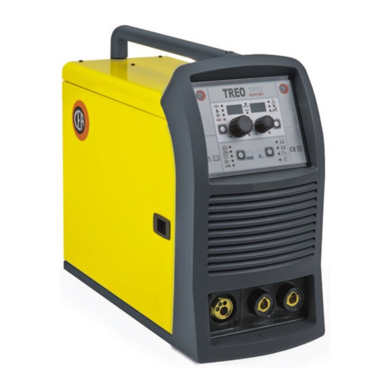
ENGLISH Description Introduction Description MULTI-FUNCTION INVERTER GENERATOR SUITABLE FOR SINGLE-PHASE POWER SUPPLIES FOR MIG-MAG, MMA, Technical data and TIG WELDING (with “Lift” type ignition) TREO 1800 synergic makes it possible to do high quality MIG- Usage limits (IEC 60974-1) MAG welding on all materials, also guaranteeing excellent per- How to lift up the machine formance for TIG welding with “Lift”... -
Page 3: Technical Data
- MMA welding: Technical data - “Arc Force” adjustable to select the best dynamic char- acteristics for the welding arc. The general technical data of the system are summarized in - “Hot Start” adjustable to improve ignition with particu- table 1. larly difficult electrodes. -
Page 4: How To Lift Up The Machine
er is ready for use again (Automatic reset error). This equip- Persons fitted with pace-makers, hearing aids and similar ment is built to have a protection level of IP 23 S, which means: equipment must consult their doctor before going near a ma- •... -
Page 5: Command And Control Units (Fig. A)
Command and control units (Fig. A) Pos. 1 “TX” control panel. Pos. 2 Fast coupling straight polarity. Pos. 3 Fast coupling reverse polarity. Pos. 4 Centralised MIG-MAG torch connection. Pos. 5 Power supply switch. In the “O” position the welder is off. -
Page 6: Mig-Mag Welding With Gas
MIG-MAG welding with GAS To begin MIG-MAG welding, carry out the following tasks (with the machine switched off): 1 - Connecting the cables (Fig. C1-C2) 1) Connect the gas hose to the pressure reducer fitted on the cylinder beforehand. Gas cylinders are supplied with a pressure reducer to adjust pressure of the gas used for welding. -
Page 7: Mig-Mag Welding Without Gas
MIG-MAG welding without GAS To begin MIG-MAG welding without gas, carry out the follow- ing tasks (with the machine switched off): 1 - Connecting the cables (Fig. D1-D2) 1) Screw the torch to the centralised connection on the front panel of the welding machine (Pos. 4, Fig. A). 2) Connect up the earthing system cable to the rapid cou- pling marked by a + (positive) symbol and then the relevant ground clamps to the piece being welded or to its support in... -
Page 8: Interval Welding (Stitch)
To begin spot welding: possible to reduce tungsten inclusions on ignition to a mini- • Place the gas guiding nozzle perpendicular on the workpiece mum. The molten bath and the electrode are protected by and to be spot welded. inert gas (for example, Argon). This type of welding is used •... -
Page 9: Electrode Welding (Mma)
Table 4 Electrode welding (MMA) WELDING THICKNESS (mm) Ø ELECTRODE (mm) Electrode welding is used to weld most metals (different types 1,2 ÷ 2 of steel, etc.) using coated rutilic and basic electrodes with di- 1,5 ÷ 3 ameters ranging from Ø 1.6 mm to Ø 3,2 mm. 3 ÷... -
Page 10: The Pointing Out Of Any Difficulties And Their Elimination
SPARE PARTS Original spares have been specifically designed for our equip- ment. The use of spares that are not original may cause vari- ations in the performance and reduce the safety level of the equipment. We are not liable for damage due to use of spare parts that are not original. -
Page 11: Troubleshooting Table
Troubleshooting table WARNING: Any internal inspections or repairs are only to be done by qualified personnel! IMPORTANT: Remember to disconnect the mains power supply and wait for the internal capacitors to discharge (about 2 min- utes) before starting to check and repair the machine if necessary. Defect Solution The welding machine does... -
Page 12: Electro Topographical Diagram
Electro topographical diagram 2101AB10... -
Page 13: Electro Topographical Diagram Key
•1 •2 •3 •4 •5 •6 •7 •8 •9 •10 •11 L1-2-3 •12 •13 •14 •15 •16 •17 •18 •19 •20 •21 •22 Electro topographical diagram key Colour key Orange •1 Primary transformer coil •2 Secondary transformer coil •3 Polarity change terminal board •4 Gas solenoid valve •5 Mains switch •6 Secondary induct- Sky Blue ance •7 Toroidal ferrite •8 Drive motor •9 Fan motor •10 Earth terminal •11... - Page 15 Lista ricambi LEGGERE ATTENTAMENTE Spare parts list READ CAREFULLY CEA COSTRUZIONI ELETTROMECCANICHE ANNETTONI S.p.A. C.so E. Filiberto, 27 - 23900 Lecco - Italy Tel. ++39.0341.22322 - Fax ++39.0341.422646 Cas. Post. (P.O.BOX) 205 e-mail: cea@ceaweld.com - web: www.ceaweld.com...
- Page 16 Tubetto guidafilo 53mm 53mm Wire guide tube 236639 Attacco Euro con tubetto guidafilo Euro connection with wire guide tube 414326 Chiavistello Lock 420574 Coperchio mobile senza adesivo logo CEA Mobile cover without CEA logo sticker 468704 Adesivo logo CEA CEA logo sticker...
- Page 17 Mains switch 427895 Pressacavo completo di ghiera Cable clamp with lock ring 235960 Cavo alimentazione Mains cable 427866 Pressacavo completo di ghiera Cable clamp with lock ring 420573 Coperchio lato fisso senza adesivo logo CEA Fixed cover without CEA logo sticker...
- Page 18 TREO 1800 Pos. Descrizione Description synergic 450067 Scatola di protezione cambio polarità Change polarity protection box 240561 Meccanismo di trascinamento con motoriduttore Wire feed mechanism with motorgear 404913 Telaio metallico interno Internal metallic chassis 241844 Mozzo bobina Hub coil 431333 Piedino d'appoggio Support foot...
- Page 19 TREO 1800 Pos. Descrizione Description synergic 424019 Distanziale scheda filtro EMC EMC filter PCB spacer 377146 Scheda filtro EMC EMC filter PCB 413471 Cablaggio ausiliario Auxiliary wiring 425938 Elettrovalvola gas Gas solenoide valve 485040 Tubo gas Gas tube 353448 Isolamento laterale coperchio Cover insulation 486386 Motore ventilatore...
- Page 20 IT Complessivo meccanismo di EN Complete entrainment mechanism with 2 rolls trascinamento a 2 rulli 2050H858 Pos. Cod. Descrizione Description 444468 Motore 24V/40W 24V/40W Motor 602025 Seeger 10mm Seeger 10mm Tab. A Rullo Ø 30 mm Feed roll Ø 30 mm 487803 Vite di fissaggio Fixing screw...
- Page 21 IT Rulli di trascinamento EN Drive mechanism FILO Diametro filo Diametro rulli Rullo inferiore WIRE Wire diameter Rolls diameter Lower roller 0,6 ÷ 0,8 mm Ø 30 mm 459170 0,8 ÷ 1,0 mm Ø 30 mm 459172 Acciaio 0,9-1,0 ÷ 1,2 mm Ø...
- Page 23 Operator’s manual READ CAREFULLY CEA COSTRUZIONI ELETTROMECCANICHE ANNETTONI S.p.A. C.so E. Filiberto, 27 - 23900 Lecco - Italy Tel. ++39.0341.22322 - Fax ++39.0341.422646 Cas. Post. (P.O.BOX) 205 e-mail: cea@ceaweld.com - web: www.ceaweld.com...
- Page 24 ENGLISH Introduction Electrode (MMA) 1 - WELDING PROCESS SELECTION Control panel 2 - SELECTION OF WELDING PROGRAM KEY AND KNOB COMMANDS 3 - SPECIAL FUNCTIONS “Fx” SELECTION DISPLAY AND LED INDICATIONS 4 - PRE-SETTING 5 - WELDING Switching on the welding 6 - HOLD machine and initial screen 7 - ACTIVATING THE VRD DEVICE...
-
Page 25: Control Panel
■ ENCODER knob - V Control panel This is used to set and edit the PARAMETERS - V based on the corresponding LED switched on and the value highlighted on the KEY AND KNOB COMMANDS DISPLAY PARAMETERS - V display, required for correct functio- ning of the machine. -
Page 26: Display And Led Indications
■ VRD LED DISPLAY AND LED INDICATIONS The Voltage Reduction Device (VRD) is a safety device that redu- ces voltage. It prevents voltages forming on the output terminals that may pose a danger to people. ▪ HOLD FUNCTION LED ▪ VRD LED Two-tone LED (off - red - green) indicates enabling of the VRD. -
Page 27: Loading Of The Wire
The rotation of one of the two ENCODER Knobs - A (E1) or V (E2) Special functions “Fx” by the operator during the display of the string version software provokes the block (for 1 second), on both the displays, of To access the SPECIAL FUNCTIONS “Fx”... - Page 28 2) You can access the SECOND LEVEL MENU (except for when Within the SECOND LEVEL MENU: the JOB process is active) only via the SPECIAL FUNCTIONS • Rotate the ENCODER - A knob (E1) to select the special MENU (SPC FnC) parameter, as follows: function required.
-
Page 29: Special Functions Menu (Spc Fnc)
FACTORY DEFAULT (FAC) 3) To exit from the SPECIAL FUNCTIONS “Fx” menu: • Press and release once the SPECIAL FUNCTIONS “Fx” Key (T3) if you are on the FIRST LEVEL MENU. WARNING: This operation, if performed, brings about the total •... -
Page 30: Safety Calibration Code (Scc)
SAFETY CALIBRATION CODE (SCC) • The procedure of calibration is carried out in 3 different phases: Calibration parameter SM1 (MINIMUM SPEED) Press and release the torch button, then wait for the auto- ATTENTION: This operation, if carryed on, optimizes the effi- matic arrest of the wire. -
Page 31: Mig-Mag Synergic
2 - SELECTION OF WELDING PROGRAMME • At the end of the procedure, the software present in the welder will immediately re-calculate the characteristic curve of the en- gine, rendering it suitable to use. PROGRAM TABLE (*) WARNING: The motor CANNOT be stopped during the measu- MIG-MAG PROCESS ring time! •... -
Page 32: Special Functions "Fx" Selection
4 - SPECIAL FUNCTIONS “Fx” SELECTION Then there is an independent parameter, SPECIAL FUNCTIONS The SPECIAL FUNCTIONS “Fx” that are only available in the MIG- MENU (SPC FnC), that provides access to the SECOND LEVEL MENU. MAG synergic welding process are shown below. For all the other explanations regarding this menu make reference to the relative ■... -
Page 33: Welding
Example: ELECTRONIC INDUCTANCE • PARAMETER DISPLAY screen - V (D2) Press the PARAMETER SELECTION - V key (T4) until the LED that corresponds to the ELECTRONIC INDUCTANCE switches on. Turn the ENCODER - V knob (E2) to change the value shown ARC LENGTH ADJUSTMENT on the PARAMETER DISPLAY - V screen (D2). -
Page 34: Special Functions "Fx" Selection
3 - SPECIAL FUNCTIONS “Fx” SELECTION • STITCH WELD PAUSE (Srt) - Time of pause between one wel- The SPECIAL FUNCTIONS “Fx” that are only available in the MIG- ding in tracts and another. • BURN BACK (bub) - Regulates the length of the wire after wel- MAG manual welding process are shown below. -
Page 35: Welding
In this phase the displays show: • PARAMETER DISPLAY screen - A (D1) WELDING VOLTAGE ELECTRONIC INDUCTANCE WELDING CURRENT WIRE SPEED - WELDING CURRENT ( ): the last current value measured. Example: ELECTRONIC INDUCTANCE - WIRE SPEED ( ): the value previously set. Press the PARAMETER SELECTION - V key (T4) until the LED •... -
Page 36: Selection Of Welding Program
2 - SELECTION OF WELDING PROGRAM 4 - PRE-SETTING Before welding it is possible to set the following parameters: PROGRAM TABLE MMA PROCESS MATERIAL DISPLAY TYPE CLASS WELDING CURRENT Basic E7018 Rutil E6013 Cr-Ni E316L Select the PROGRAMME of welding by pressing and releasing, even several times if necessary, the PROGRAM SELECTION key (T1) until the corresponding LED is lit and after that rotating the ENCODER knob - V (E2) until obtaining on the PARAMETER DI-... -
Page 37: Hold
During the welding the operator can change the following para- To interrupt the HOLD function and go back to the PRESETTING meters: phase before 15 seconds have passed, simply turn one of the two • WELDING CURRENT ( ). ENCODER (E1-E2) knobs. •... -
Page 38: Tig With "Lift" Striking
4 - WELDING TIG with “Lift” striking During the welding the display shows: • PARAMETER DISPLAY screen - A (D1) Start the welder by pressing the switch, located on the back pa- nel, at the position I. 1 - WELDING PROCESS SELECTION Select the TIG PROCESS of welding with “Lift”... -
Page 39: Job
To interrupt the HOLD function and go back to the PRESETTING WARNING: If all the automatic welding points (JOBS) are occu- phase before 15 seconds have passed, simply turn one of the two pied, the check automatically goes to the first automatic welding ENCODER (E1-E2) knobs. -
Page 40: Welding
4 - WELDING 7 - DELETING A JOB SAVED During the welding the display shows the values, if possible mea- In JOB mode, holding down the PARAMETER SELECTION - A sured, of the active parameters, based on the type of welding pro- (T1) and PARAMETER SELECTION - V (T4) keys down simul- cess, memorised within the selected JOB. - Page 41 Error Error Error description and possible Error Error Error description and possible condition code diagnosis condition code diagnosis USER FILE MISSING POWER LIMITATION NON automatic reset error. This alarm appears if the power limit E1.1 Immediately contact technical is exceeded. The alarm alternates assistance dept.
Need help?
Do you have a question about the TREO 1800 Synergic MIG-MAG and is the answer not in the manual?
Questions and answers