Table of Contents

Related Manuals for CEA DIGITECH vision PULSE 3200


Summary of Contents for CEA DIGITECH vision PULSE 3200
- Page 1 Operator’s manual READ CAREFULLY CEA COSTRUZIONI ELETTROMECCANICHE ANNETTONI S.p.A. C.so E. Filiberto, 27 - 23900 Lecco - Italy Tel. ++39.0341.22322 - Fax ++39.0341.422646 Cas. Post. (P.O.BOX) 205 E-mail: cea@ceaweld.com - web: www.ceaweld.com...
- Page 2 ENGLISH Introduction Introduction Description Thank you for having purchased our product. Please read in- structions on use in this manual as well as the safety rules Operating features given in the attached booklet and follow them carefully to get the best performance from the equipment and be sure that the Technical data parts have the longest service life possible.
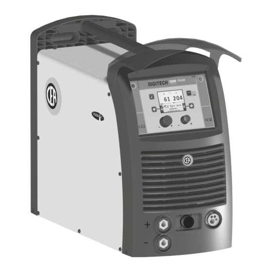
- Page 3 The general technical data of the system are summarized in table 1. Opening the packaging Table 1 The system essentially consists of: DIGITECH vision • DIGITECH vision PULSE 3200 weld unit. PULSE 3200 Model • Separately: MIG-MAG welding - MIG-MAG welding torch (optional).
- Page 4 This system is cooled by means of the forced circulation of air, and must therefore be placed in such a way that the air may be easily sucked in and expelled through the apertures made 3 4 4 3 in the frame. Assemble the system in the following way: •...
- Page 5 MIG-MAG / PULSE MIG / DOUBLE PULSE MIG Welding To begin MIG-MAG / PULSE MIG / DOUBLE PULSE MIG weld- ing, carry out the following tasks (with the machine switched off). 1 - Connecting the cables (Fig. C) • Connect the gas hose to the pressure reducer fitted on the cylinder beforehand.
- Page 6 14 and 20 lit/min to suit the cur- rent used for welding. Electrode welding (MMA) On the DIGITECH vision PULSE 3200 machine, electrode welding is used to weld most metals (different types of steel, etc.) using coated rutilic and basic electrodes with diameters ranging from Ø...
- Page 7 The current intensity to be used for the different types of weld- DIGITECH vision PULSE 3200 ing, within the field of regulation shown in table 4 is: • High for plane, frontal plane and vertical upwards welding.
- Page 8 AIR AND/OR WATER COOLED UP/DOWN TORCH ANALOGUE INPUTS This command (must be inserted in the relevant connector at These inputs must be piloted by a direct voltage that can be Pos. 3, Fig. B) and works as an alternative: regulated between 0V and 10V. •...
- Page 9 Meaning of graphic symbols on machine Negative pole snap-in connector Power supply switch System for use in environments with in- Warning! creased risk of electroshock Before using the equipment you should Product suitable for free circulation in the carefully read the instructions included in European Community this manual Danger! Parts moving...
- Page 10 Wiring diagram COLOUR KEY Orange-Black White-Black Black Orange Grey Red-Black Sky Blue-Red Yellow Pink Sky Blue Yellow-Green White Brown Green Blue Black-Sky Blue Violet...
- Page 11 KEY TO THE ELECTRICAL DIAGRAM •1 •2 •3 •4 •5 •6 •7 •8 •9 •10 •11 •12 F-EMC •13 •14 •15 •16 •17 •18 •19 •20 •21 •22 •23 •24 MV1-2 •25 •26 •27 •28 •29 •30 •31 •32 •33 •34 S-INT DIG S-INV...
- Page 13 Lista ricambi LEGGERE ATTENTAMENTE Spare parts list READ CAREFULLY CEA COSTRUZIONI ELETTROMECCANICHE ANNETTONI S.p.A. C.so E. Filiberto, 27 - 23900 Lecco - Italy Tel. ++39.0341.22322 - Fax ++39.0341.422646 Cas. Post. (P.O.BOX) 205 E-mail: cea@ceaweld.com - web: www.ceaweld.com...
- Page 14 Ø29mm Knob without index 468725 Adesivo logo CEA Ø30mm CEA logo sticker Ø30mm 352473 Pannello frontale senza adesivo logo CEA Ø30mm Front panel without CEA logo sticker Ø30mm 236642 Attacco Euro con tubetto guidafilo Euro connection with wire guide tube...
- Page 15 Cavo alimentazione Mains cable 352459 Pannello posteriore Rear panel 485040 Tubo gas Gas tube 419049 Connettore alimentazione impianto di raffreddamento Cooling system power connector 420687 Coperchio lato destro con adesivo logo CEA Right cover with CEA logo sticker 414326 Chiavistello Lock...
- Page 16 Pos. Cod. Descrizione Description 404930 Basamento Base 241840 Mozzo bobina Spool holder Pag. 6 Meccanismo di trascinamento Wire feed mechanism assembly 488315 Condensatore di protezione attacco rapido Quick connection protection capacitor 400000 Adattatore Adaptor 444469 Motoriduttore con encoder Drive motor with encoder 453832 Scatola protezione motoriduttore Drive motor protection box...
- Page 17 (assembly) Pos. Cod. Descrizione Description 435760 Interruttore alimentazione Mains switch 376887 Filtro EMC EMC Filter 425938 Elettrovalvola Solenoide valve 377134 Scheda condensatori Capacitors PCB 377113 Scheda power source Power source PCB 377110 Scheda comando motore Motor control PCB 413496 Assieme cablaggio ausiliario con flat cable Auxiliary wiring with flat cable assembly 449585 Pianale superiore...
- Page 18 IT Complessivo meccanismo di EN Complete entrainment mechanism with 4 rolls trascinamento a 4 rulli 16 15 14 20 21 Pos. Cod. Descrizione Description 307271 Base meccanismo di trascinamento Wire feed mechanism base 437075 Dispositivo di pressione rulli Pressure device 356963 Complessivo leva di pressione sinistra Pressure arm left complete...
- Page 19 IT Rulli di trascinamento EN Drive mechanism Rullo inferiore Rullo superiore FILO Diametro filo TWIN kit (doppia cava) Ø37 mm (cava singola) Ø30 mm WIRE Wire diameter Lower roller Upper roller TWIN kit (double slot) Ø37 mm (single slot) Ø30 mm 0,6 ÷...
- Page 20 Operator’s manual READ CAREFULLY CEA COSTRUZIONI ELETTROMECCANICHE ANNETTONI S.p.A. C.so E. Filiberto, 27 - 23900 Lecco - Italy Tel. ++39.0341.22322 - Fax ++39.0341.422646 Cas. Post. (P.O.BOX) 205 E-mail: cea@ceaweld.com - web: www.ceaweld.com...
-
Page 21: Table Of Contents
ENGLISH Introduction ..................4 General notes . - Page 22 Error condition ................. 34 SETUP Menu .
-
Page 23: Introduction
Introduction This manual describes the functions of the software operating the following control panels: • DH 32 VS 32 • DH 33 + HT5 VS 33 + HT5 • DH 40 + HT5 VS 40 + HT5 • DH 50 + HT5 VS 50 + HT5 Functioning of the panels listed above is identical (the functions are the same but the characteristics differ depending on the type of machine they are fitted on (e.g.: current regulation field). -
Page 24: Welding Mode Selection Key (Not Used With Dh 32 And Vs 32)
WELDING MODE SELECTION Key (not used with DH 32 and VS 32) Each time this is pushed the following welding modes can be selected (only for pulsed and double pulsed MIG, synergic and manual welding processes) on the feeder (on the welding machine the welding mode is selected using a specific menu - see the appropriate paragraphs) according to a specific sequence: 2T LED 4T LED... -
Page 25: Switching On The Welding Machine
• The VISION S shows the SCREEN SAVER. CREEN • On both the HT5 displays for the wire feeder, “CEA” appears and scrolls continuously. VISION Screen Display HT5 (not used with DH 32 and VS 32) The SCREEN SAVER mode can be exited in one of the following ways: •... -
Page 26: Welding Process Selection Menu (Process)
WELDING PROCESS SELECTION Menu (PROCESS) “DH” / “VS” CONTROL PANEL To access the PROCESS SELECTION Menu (PROCESS) push the MENU K MENU K ENTER/MEM K MIG PULSE MIG DUAL PULSE MIG/MAG SYNERGIC MIG/MAG MANUAL VISION.COLD VISION.PIPE VISION.POWER 1011 Fe G3 SI-1 Ø 0.8 Ar 16-20% CO2 ENCODER K - SX MENU K... -
Page 27: Mig-Mag, Mig Pulse/Dual Pulse (Vision.pipe, Vision.cold, Vision.power, Vision.ultraspeed Only If Activated)
MIG-MAG, MIG pulse/dual pulse (Vision.PIPE, Vision.COLD, Vision. POWER, Vision.ULTRASPEED only if activated) 1 - PROGRAM SELECTION Menu (PROGRAM) “DH” / “VS” CONTROL PANEL To access the PROGRAM SELECTION Menu (PROGRAM) push the MENU K MENU K ENTER/MEM K MATERIAL Ø 1011 Fe G3 SI-1 0.8 Ar 16-20% CO2 1012 Fe G3 SI-1... -
Page 28: Special Functions Menu (Set Up Fx)
“HT5” CONTROL PANEL (not used with DH 32 and VS 32) To access the WELDING MODE SELECTION Menu (MODE) push the WELDING MODE SELECTION K WELDING MODE SELECTION K WELDING MODE SELECTION LED WELDING MODE SELECTION K Scrolls the various welding modes available in succession. WELDING MODE SELECTION LED Displays the welding mode selected. - Page 29 “HT5” CONTROL PANEL (not used with DH 32 and VS 32) To access the SPECIAL FUNCTIONS Menu (SET UP Fx) push the SPECIAL FUNCTIONS (F PARAMETER DISPLAY S CREEN ENCODER K ENCODER K SPECIAL FUNCTIONS (F SPECIAL FUNCTIONS (F ) LED PARAMETER DISPLAY S Displays the selected SPECIAL FUNCTION (Fx).
- Page 30 PARAMETER DISPLAY Screen - V Welding mode PARAMETER DISPLAY Special function Screen - A FINAL CURRENT -30% -100% - +50% ● ● ● ● FINAL ARC LENGTH -30 - +30 ● (*) ● (*) ● (*) ● (*) FINAL CRATER TIME 0.0s (0.0 - 20.0)s ●...
- Page 31 The SPECIAL FUNCTIONS (Fx) for the MIG-MAG manual process correspond to the feeder (when fitted) as follows: Table B PARAMETER DISPLAY Screen - V Welding mode PARAMETER DISPLAY Special function Screen - A PRE GAS 0.1s (0.0 - 2.0)s ● ●...
-
Page 32: Pre-Setting
4 - PRE-SETTING “DH” / “VS” CONTROL PANEL MENU K 217 29.4 SX K DX K PROGRAM 1011 Fe G3 SI-1 Ø 0.8 Ar 16-20% CO2 ENCODER K - SX ENCODER K - DX Used to access the PROCESS SELECTION Menu (PROCESS) and subsequent menus, as MENU K applicable. -
Page 33: Welding
ENCODER K Adjusts the parameter displayed by the PARAMETER DISPLAY S - V. CREEN GAS K Activates the flow of gas. Only enables entering and exit afterwards from the SPECIAL FUNCTIONS Menu (SET UP SPECIAL FUNCTIONS (F Fx) on the HT5 panel and not on the DH panel. 5 - WELDING When welding takes place the fields in the displays show the same values as those included for pre-setting with the difference that now they are those measured. -
Page 34: Hold
6 - HOLD When welding ends the fields in the display must show the same values that were displayed during welding, with the difference that they are now values defined as HOLD. In this phase the VISION S shows the HOLD box highlighted, while on the HT5 CREEN panel the HOLD F LED flashes until the end of the HOLD Function. -
Page 35: Wire Loading
7 - WIRE LOADING The purpose of this menu it to allow the operator to load the welding wire and set the loading speed, only when welding is not is progress. If the wire loading function is activated (also see the CONFIG menu), to enable it hold the torch button or the load- ing button on the feeder down for 4 seconds. -
Page 36: Mma
Select the MMA welding process by using the MENU as explained on page 7. 1 - PROGRAM SELECTION Menu (PROGRAM) “DH” / “VS” CONTROL PANEL To access the PROGRAM SELECTION Menu (PROGRAM) push the MENU K MENU K ENTER/MEM K TYPE 3100 MMA Basic 3200 MMA Cr Ni... - Page 37 “HT5” CONTROL PANEL (not used with DH 32 and VS 32) To access the SPECIAL FUNCTIONS Menu (SET UP Fx) push the SPECIAL FUNCTIONS (F PARAMETER DISPLAY S CREEN PARAMETER DISPLAY S CREEN ENCODER K ENCODER K SPECIAL FUNCTIONS (F SPECIAL FUNCTIONS (F ) LED PARAMETER DISPLAY S...
-
Page 38: Pre-Setting
3 - PRE-SETTING “DH” / “VS” CONTROL PANEL MENU K ENTER/MEM K 60 70.0 SX K DX K PROGRAM 3200 MMA Cr Ni ENCODER K - SX ENCODER K - DX Used to access the PROCESS SELECTION Menu (PROCESS) and subsequent menus, as MENU K applicable. -
Page 39: Welding
4 - WELDING When welding takes place the fields in the displays show the same values as those included for pre-setting with the difference that now they are those measured. “DH” / “VS” CONTROL PANEL 60 70.0 PROGRAM 3200 MMA Cr Ni “HT5”... -
Page 40: Hold
5 - HOLD When welding ends the fields in the display must show the same values that were displayed during welding, with the difference that they are now values defined as HOLD. In this phase the VISION S shows the HOLD box highlighted, while on the HT5 CREEN panel the HOLD F LED flashes until the end of the HOLD Function. -
Page 41: Activating The Vrd Device
6 - ACTIVATING THE VRD DEVICE The Voltage Reduction Device (VRD) is a safety device that reduces voltage. It prevents voltages forming on the output termi- nals that may pose a danger to people. The standard settings and those defined beforehand by do not provide for the VRD to be active on the welding machine and so the VISION S does not normally provide any indication. -
Page 42: Tig Lift
TIG LIFT Select the TIG LIFT welding process by using the MENU as explained on page 7. 1 - SPECIAL FUNCTIONS Menu (SET UP Fx) TIG LIFT “DH” / “VS” CONTROL PANEL To access the SPECIAL FUNCTIONS Menu (SET UP Fx) push the MENU K MENU K ENTER/MEM K SX K... -
Page 43: Pre-Setting
The SPECIAL FUNCTIONS (Fx) related to the TIG LIFT process correspond as follows to those on the wire feeder: PARAMETER DISPLAY Screen - V Special function PARAMETER DISPLAY Screen - A Default Range UP SLOPE 0.0s (0.0 - 5.0)s DOWN SLOPE 2.0s (0.0 - 8.0)s TIG PULSE DELTA CURRENT... -
Page 44: Welding
ENCODER K Adjust the value of the parameter WELDING CURRENT ( ). Displays the value of the parameter WELDING VOLTAGE ( ). PARAMETER DISPLAY S CREEN The WELDING VOLTAGE shown is the measured voltage. PARAMETER SELECTION LED - V The LED unit shows the WELDING VOLTAGE ( ) switched on. 3 - WELDING TIG LIFT When welding takes place the fields in the displays show the same values as those included for pre-setting with the difference... -
Page 45: Hold
4 - HOLD TIG LIFT When welding ends the fields in the display must show the same values that were displayed during welding, with the difference that they are now values defined as HOLD. In this phase the VISION S shows the HOLD box highlighted, while on the HT5 CREEN panel the HOLD F... -
Page 46: Job/Sequences
JOB/SEQUENCES 1 - Creating and saving / editing and overwriting a JOB/SEQUENCES (*) JOB/SEQUENCES “DH” / “VS” CONTROL PANEL MENU K ENTER/MEM K 211 24.8 SX K DX K PROGRAM 0011 Fe G3 SI-1 Ø 0.8 Ar 16-20% CO2 ENCODER K - SX ENCODER K - DX... -
Page 47: Job/Sequences Selection Menu
2 - JOB/SEQUENCES SELECTION Menu JOB/SEQUENCES WARNING: All the parameters saved within a JOB/SEQUENCE (including SPECIAL FUNCTIONS (Fx)) can be viewed but not edited! “DH” / “VS” CONTROL PANEL To access the JOB/SEQUENCES SELECTION Menu push the MENU K MENU K ENTER/MEM K JOB PRG PROCESS... -
Page 48: Pre-Setting
The LED unit indicates the welding mode saved in the JOB selected, which is coherent with WELDING MODE SELECTION LED the VISION S CREEN Displays the JOB number also selected in the SEQUENCES or the value for the parameter PARAMETER DISPLAY S CREEN indicated by the PARAMETER SELECTION LED - V. - Page 49 “HT5” CONTROL PANEL (not used with DH 32 and VS 32) PARAMETER DISPLAY S HOLD Function LED CREEN PARAMETER DISPLAY S CREEN PARAMETER SELECTION LED - A PARAMETER SELECTION LED - V PARAMETER SELECTION K PARAMETER SELECTION K ENCODER K ENCODER K WIRE K GAS K...
-
Page 50: Welding
4 - WELDING JOB/SEQUENCES WARNING: All the parameters saved within a JOB (including SPECIAL FUNCTIONS (Fx)) can be viewed but not edited! “DH” / “VS” CONTROL PANEL MENU K m/min 11.1 33.3 SX K DX K MENU K SX K DX K 1011 - Welding sequence Fe G3 SI-1 Ø... -
Page 51: Hold
The LED unit indicates the welding mode saved in the JOB selected, which is coherent with WELDING MODE SELECTION LED the VISION S CREEN Displays the JOB number also selected in the SEQUENCES or the value for the parameter PARAMETER DISPLAY S CREEN indicated by the PARAMETER SELECTION LED - V. - Page 52 HOLD 1011 - Welding sequence Fe G3 SI-1 Ø 0.8 Ar 16-20% CO2 “HT5” CONTROL PANEL (not used with DH 32 and VS 32) HOLD Function LED...
-
Page 53: Error Condition
Error condition WARNING: Under normal conditions of use it is not possible to open the “ERROR LOG Menu” display since the alarm message appears instantaneously on the VISION S as soon as the problem arises on the welding plant. At this stage it is not possi- CREEN ble to weld! As soon as the error message appears:... -
Page 54: Setup Menu
PLEASE NOTE: After resetting has been completed, during normal operation of the machine, the VISION S will still show the CREEN ), but this can be removed visually from the display by simply pushing the MENU error signal to inform the operator of the event ( . -
Page 55: Job Edit
JOB EDIT SETUP Menu The purpose of this menu is to allow the operator to copy or delete a JOB (automatic welding point) entered previously. To access the JOB EDIT Menu from the SETUP Menu: • Turn the ENCODER K - SX to select the desired icon. -
Page 56: Seq Edit
SEQ EDIT SETUP Menu The purpose of this menu is to allow the operator to create, copy, overwrite, or delete a welding sequence. To access the SEQ EDIT Menu from the SETUP Menu: • Turn the ENCODER K - SX to select the desired icon. •... - Page 57 Use the DX K to remove the JOB from the section of the sequence selected using the NAME Sequenza Saldatura JOB PRG PROCESS ENCODER K - SX. 001 1011 MIG PULSE 100A 003 2011 MIG DUAL PULSE 100A Push the ENTER/MEM K to be able to edit the sequence name.
-
Page 58: Password
Confirm using the SX K or cancel using the DX K NAME # JOB Welding sequence Welding sequence 1 Welding sequence 2 Welding sequence 2 DELETE SEQ. 006? EDITING A SEQUENCE Select the position of the sequence to be edited using the ENCODER K - SX and push the ENTER/MEM The sequence to be edited will be displayed, with all already described for creating the sequence. -
Page 59: Blocks
EDITING THE EXISTING PASSWORD WARNING: This operation is only possible after having accessed the SETUP Menu using the password you wish to edit! To edit the existing PASSWORD proceed as follows: SET PASSWORD • Make sure the VISION S shows the PASSWORD entered previously (a number that must be CREEN between 001 and 999). -
Page 60: Config
Block type Description LEVEL 1 PARTIAL BLOCK The operator can weld using the parameters set prior to the block and may make adjustments and/or changes to the welding parameters using the knobs on the control panels on the welding machine and the wire feeder (if fitted). BLOCK TYPE LEVEL 1 LEVEL 2... - Page 61 Advanced function Description ADVANCED CONFIGURATION If enabled, this configuration offers the welder the following additional menus (the following icons will be created in the ADVANCED SETUP Menu): • ADVANCED CONFIG • WELD LOG LANGUAGE ENGLISH ADVANCED CONFIGURATION ENABLED ADVANCED WELDING MODE DISABLED COOLING MODE ON DEMAND...
-
Page 62: Factory Reset
FACTORY RESET SETUP Menu The purpose of this menu is to allow the operator to return the welding machine partially or totally to the factory settings. To access the FACTORY RESET Menu from the SETUP Menu: • Turn the ENCODER K - SX to select the desired icon. -
Page 63: Info
All the functions included in this menu can be used as follows: • Choose the function (e.g. RESET PROCESS DATA) that RESET PROGRAM (0011) RESET PROGRAM (0011) RESET PROGRAM (0011) RESET PROCESS DATA MIG/MAG SYNERGIC RESET PROCESS DATA MIG/MAG SYNERGIC RESET PROCESS DATA MIG/MAG SYNERGIC you intend to use by rotating the ENCODER K - SX. - Page 64 Software Description ROBOT INTERFACE SW. VERS. This indicates the software version loaded in the robot interface board, if applicable. POWER SOURCE SW. VERS. WIRE FEEDER SOFTWARE VER. 1 WIRE FEEDER SOFTWARE VER. 2 ROBOT INTERFACE SW. VERS. H02-01.00 F06-01.01 This indicates the serial number for the microprocessor contained in the digital interface board.
-
Page 65: Network
Software Descrizione ENABLED OPTIONS The special programs enabled, specifically: • PULSED • ECP estended curves package ENABLED OPTIONS • VISION.COLD COLD VISION.COLD • VISION.PIPE EXTENDED CURVES PACKAGES PIPE VISION.PIPE • VISION.POWER POWER VISION.POWER PULSED PULSED • VISION.ULTRASPEED ULTSPEED VISION.ULTRASPEED The contents of thus menu are for information only, the operator cannot change anything they can only read the information con- tained by scrolling the various options available in the menu by rotating the ENCODER K - SX. -
Page 66: Error Log
Function Description GATEWAY This indicates the gateway number to which the welding machine has been assigned. LINK STATUS NOT ACTIVE CONFIGURATION DHCP IP ADDRESS 169.254.136.178 NETMASK 255.255.0.0 GATEWAY 0.0.0.0 Digitech Vision 5000 [FX00204904080100] To exit the DATA IN-OUT Menu and go back to the SETUP Menu: •... - Page 67 Error Error code Error description and possible diagnosis condition OVER AND UNDER VOLTAGE E0.1 Automatic reset error. OVER VOLTAGE E0.2 Automatic reset error. UNDER VOLTAGE E0.3 Automatic reset error. OVER CURRENT E0.4 Automatic reset error. REMOTE COMMANDS E0.5 No feed for remote commands. NON automatic reset error.
- Page 68 Error Error code Error description and possible diagnosis condition CALIBRATION FILE MISSING NON automatic reset error. E1.3 Immediately contact technical assistance dept. Error visible on VISION S ONLY in the event of a fault and NOT in the ERROR LOG Menu. CREEN MMA DEFAULTS MISSING NON automatic reset error.
- Page 69 Error Error code Error description and possible diagnosis condition MIG PROGRAMS MISSING NON automatic reset error. E5.0 Immediately contact technical assistance dept. Error visible on VISION S ONLY in the event of a fault and NOT in the ERROR LOG Menu. CREEN PULSED MIG WELDING PROGRAMMES MISSING NON automatic reset error.
-
Page 70: Advanced Setup Menu
PLEASE NOTE: If, when switching on, the error status presents itself again, immediately contact Technical Assis- tance Department. This is necessary so that our technical assistance dept (that must be contacted each time the error messages appear on the welding machine’s operator interface) is able to resolve the problems more easily and as quickly as possible, thanks to the reports by the user, and also because, in the meantime the welding machine does not allow the operator to do their work. -
Page 71: Advanced Config
ACCESSING THE SUB-MENUS To access the sub-menus included in the ADVANCED SETUP Menu, you must: SETUP • Turn the ENCODER K - SX to select the desired icon. • Push the ENTER/MEM K “HT5” CONTROL PANEL (not used with DH 32 and VS 32) It is not possible to access the ADVANCED SETUP Menu and all the related sub-menus using the “HT5”... -
Page 72: Advanced Mode
Advanced function Description ENERGY SAVING By rotating the ENCODER K - DX (this operation does not require confirmation) it is possible to choose the energy saving mode you prefer from the 3 available for the welding plant: • STANDARD - Energy saving is achieved by the screen saver being activated for the ARC ON TIMER 0 gg. - Page 73 Advanced function Description CRATER If enabled, when working in ADVANCED mode, this function provides the operator with further welding modes related to the CRATER as well as the 2 special functions explained below that make it possible to vary the length of the arc in the welding crater, when using MIG (pulsed, double pulsed, synergic, and manual) welding processes.
-
Page 74: Equipment Layout
EQUIPMENT LAYOUT ADVANCED SETUP Menu The purpose of this menu is to allow the operator to manage connections of components and accessories that are part of the welding plant. To access the EQUIPMENT LAYOUT Menu from the SETUP Menu: • Turn the ENCODER K - SX to select the desired icon. - Page 75 Advanced function Description REMOTE CONTROL 1 / DISABLED - Means that REMOTE CONTROL 1-2 must not be managed by the plant, REMOTE CONTROL 2 even if it is connected up. OPTIONAL - This means that REMOTE CONTROL 1-2 can or cannot be connected to the welding plant.
- Page 76 MENU K ENTER/MEM K EQ. LAYOUT ENCODER K - SX ENCODER K - DX When in the CONFIG menu, rotate the ENCODER K - SX to select activation of robot configuration. NOTE: If robot configuration is activated when no robot interface is connected, an error message will be displayed and it will not be possible to weld.
- Page 77 Advanced function Description ROBOT BURN BACK NOT ACTIVE - In this mode, regulation of the BURN BACK is active, via the welding machine’s panel. ACTIVE - In this mode, regulation of the BURN BACK is active, via the robot interface WATER COOLER OPTIONAL board.
- Page 78 Advanced function Description DUAL FEEDER MODE SEPARATE - If a double feeder is chosen in the EQUIPMENT LAYOUT menu, in this mode the second feeder operates separately from the first. SLAVED - If a double feeder is chosen in the EQUIPMENT LAYOUT menu, in this mode WATER COOLER OPTIONAL the second feeder operates simultaneously with and parallel to the first.
-
Page 79: Weld Log
WELD LOG ADVANCED SETUP Menu The purpose of this menu is to allow the operator to know the latest welding parameters set on the machine, as well as the lat- est data saved on the machine. To access the WELD LOG Menu from the ADVANCED SETUP Menu: •... - Page 80 CEA COSTRUZIONI ELETTROMECCANICHE ANNETTONI S.p.A. C.so E. Filiberto, 27 - 23900 LECCO - ITALY Cas. Post. (P.O. BOX) 205 Tel. +39 0341 22322 - Fax +39 0341 422646 cea@ceaweld.com www.ceaweld.com ISO 9001: 2008...
Need help?
Do you have a question about the DIGITECH vision PULSE 3200 and is the answer not in the manual?
Questions and answers