Table of Contents
Advertisement
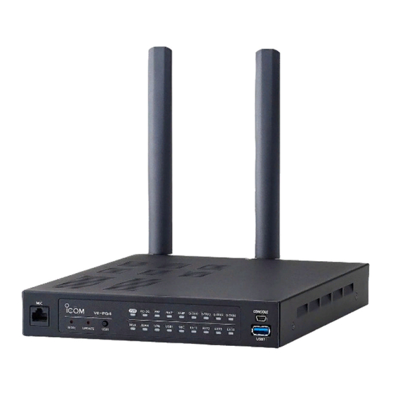
INSTALLATION GUIDE
RoIP GATEWAY
VE-PG4
INTRODUCTION
INTRODUCTION
1 BEFORE USING THE IP1000C
1. BEFORE USING THE VE-PG4
2 SETTING UP THE IP1000C SYSTEM
2. SETTING UP THE TRANSCEIVERS
3 OTHER BASIC FUNCTIONS
3. WIRELESS LAN TRANSCEIVERS
4 ABOUT THE SETTING SCREEN
4. CONFIGURING THE PBX SYSTEM
5 MAINTENANCE
5. MAINTENANCE
6 FOR YOUR INFORMATION
6. FOR YOUR INFORMATION
Advertisement
Chapters
Table of Contents

Related Manuals for Icom VE-PG4


Summary of Contents for Icom VE-PG4
-
Page 1: Installation Guide
INSTALLATION GUIDE RoIP GATEWAY INTRODUCTION INTRODUCTION VE-PG4 1 BEFORE USING THE IP1000C 1. BEFORE USING THE VE-PG4 2 SETTING UP THE IP1000C SYSTEM 2. SETTING UP THE TRANSCEIVERS 3 OTHER BASIC FUNCTIONS 3. WIRELESS LAN TRANSCEIVERS 4 ABOUT THE SETTING SCREEN 4. - Page 2 We hope you agree with Icom’s philosophy of “technology first.” Many hours of research and development went into the design of your VE-PG4. Icom is not responsible for the destruction, damage to, or performance of any Icom or non-Icom equipment, if the malfunction is because of: •...
- Page 3 INTRODUCTION Features • The VE-PG4 RoIP Gateway enables you to communicate between transceivers, wireless LAN transceivers or IP telephones, that are connected to the RoIP Gateway, through IP networks. Controls IP transceivers and wireless LAN transceivers through a 4G/3G line.
- Page 4 Icom repeater. The VE-PG4 has 4 internal AMBE+2 Vocoder corresponding to the CT-24. When you need more than 5 AMBE+2 Vocoder you can add up to 2 CT-24s to the RoIP Gateway, according to the combination of the connected devices or using voice protocol.
- Page 5 • Use numbers, characters and letters (both lower and upper case). Confirming the MAC address The MAC address of the built-in WAN or LAN module of the VE-PG4 is shown on the Serial label at the bottom of the product.
- Page 6 Installation guide (This manual, PDF type) Instructions for the system requirements, the system setup basics, maintenance, and the specifications. It can be downloaded from the Icom website. Operating guide (PDF type) The detailed references for the settings in the RoIP Gateway setting screen.
-
Page 7: Table Of Contents
BEFORE USING THE VE-PG4 Section Panel description ……………………………………………………………………………………………………… 1-2 M Front panel ……………………………………………………………………………………………………… 1-2 M Rear panel ……………………………………………………………………………………………………… 1-6 M Side and bottom panels ………………………………………………………………………………………… 1-8 Feature description …………………………………………………………………………………………………… 1-9 M Expanding communication coverage ………………………………………………………………………… 1-9 M Communication between a VoIP telephone and a transceiver …………………………………………… 1-9 M Controlling wireless LAN transceivers ………………………………………………………………………... -
Page 8: Panel Description
BEFORE USING THE VE-PG4 Panel description ■ Front panel 2 3 4 5 INDICATORS [PWR] ��������� Lights green: Power is ON Blinks green: Booting up Blinks red: UID indication Not lit: Power is OFF [4G/3G] ��������� Lights green: RSSI level 2 or more in the 4G mode... - Page 9 L A USB flash drive, such as one with biometric authentication, or one with password protection is not supported. L Some USB devices may not be usable with the VE-PG4. L The VE-PG4 accepts up to two CT-24s for optional AMBE+2 vocorders.
- Page 10 BEFORE USING THE VE-PG4 Panel description ■ Front panel 2 3 4 5 INDICATORS [EXT1] ~ [EXT4] ����� Lights green: Receiving an audio signal. Lights orange: In audio/data communication with transceivers (Full duplex). Lights red: In audio/data communication with transceivers (Receive). Not lit: Condition other than the above.
- Page 11 [MIC] PORT ������� Connect to the optional speaker-microphone. Insert the speaker-microphone connector until it clicks. L Turn OFF the VE-PG4 before connecting or disconnecting the speaker- microphone. L Never connect a LAN cable to the [MIC] port. L The [MIC] and [EXT1] ports cannot be used at the same time.
-
Page 12: Rear Panel
BEFORE USING THE VE-PG4 Panel description ■ Rear panel 2 3 A1~A4 A1~A4 B1~B4 B1~B4 C1~C4 C1~C4 A1~A4 A1~A4 B1~B4 B1~B4 C1~C4 C1~C4 A1~A4 A1~A4 B1~B4 B1~B4 C1~C4 C1~C4 A1~A4 A1~A4 B1~B4 B1~B4 C1~C4 C1~C4 [ANT1]/[ANT2] CONNECTORS ����� Attach antennas to communicate with IP transceivers through the 4G/3G line. - Page 13 [EXT1] ~ [EXT4] PORTS � Connect external devices or transceivers. L Be sure that both the VE-PG4 and the connected devices or transceivers are turned OFF when connecting or disconnecting the cables. L The default settings for the [EXT] ports are:...
-
Page 14: M Side And Bottom Panels
BEFORE USING THE VE-PG4 Panel description ■ Side and bottom panels Security slot ������ Attach a security wire (user supplied). Refer to the instruction manual that comes with the security wire for details. SIM card slot ������ Install the SIM card. Ask your dealer for installation or removal. -
Page 15: Feature Description
BEFORE USING THE VE-PG4 Feature description ■ Expanding communication coverage You can communicate with Icom transceivers* through the communication port. *Only the Icom recommended transceivers. Icom transceiver (SU) Icom Icom VE-PG4 VE-PG4 transceiver transceiver [EXT1] [EXT1] IP Network Icom transceiver... -
Page 16: M Controlling Wireless Lan Transceivers
BEFORE USING THE VE-PG4 Feature description ■ Controlling wireless LAN transceivers You can communicate through IP networks using the VE-PG4 as a controller for up to 50 wireless LAN transceivers. L A wireless access point is required. L The IP100H and IP100FS are usable, as of April, 2019. - Page 17 *Displayed only when [Call Type] is set to “Talkgroup.” • Set to the VE-PG4 whether All Call includes the Talkgroup or not, or the Talkgroup Call calls the IP100FS or not. • The ID List and the destination settings set in the VE-PG4 are commonly used in each group that the IP100H and IP100FS belong to.
-
Page 18: M Connecting To The Ip Transceiver Controllers
[EXT1] IP Transceiver ■ The router function When the router function of the VE-PG4 is enabled, the devices such as PCs that are connected to the VE-PG4 can access the internet. L The Routing function is disabled as the default. -
Page 19: Installation And Connections
BEFORE USING THE VE-PG4 Installation and connections ■ Attaching the magnet legs You can the supplied 4 magnets on the bottom panel, and tighten the supplied screws to fix the magnet legs. L Never use other than the supplied screws. -
Page 20: M Attaching The Antennas
BEFORE USING THE VE-PG4 Installation and connections ■ Attaching the antennas You have to attach the supplied antennas to control IP transceivers that communicate through a 4G or 3G line. These 2 antennas function as a diversity or MIMO that provides stable communication. -
Page 21: M Setting A Static Ip Address To A Pc
To access the VE-PG4 setting screen from a PC, set a static IP address to the PC. L As the default for the VE-PG4, the IP address is set to “192.168.0.1,” and the DHCP server is set to “Disable.” The following steps shows how to set a static IP address (example: 192.168.0.100), based on Microsoft Windows 10. -
Page 22: M Connecting The Cables And The Pc
BEFORE USING THE VE-PG4 Installation and connections ■ Connecting the cables and the PC Verify the indications Check the LAN cable connection if no indicator lights. Lights: Connected Blinks: Communicating q green: 1000BASE-T w orange: 10BASE-T/100BASE-TX VE-PG4 (Default: 192.168.0.1) Connect to the power supply... -
Page 23: The Setting Screen
• The VE-PG4 Setting screen is displayed. (See the next page.) About web browsers • We recommend using Microsoft Internet Explorer 11 or later with the VE-PG4. The screen may not be correctly displayed on the other web browsers. • Enable JavaScript and set to accept cookies on your web browser to correctly display the setting screen. -
Page 24: M Setting Screen Description
BEFORE USING THE VE-PG4 The setting screen ■ Setting screen description Refer to the Operating guide for each setting item details. Menu list �������� Displays the list on a menu line. When you click each menu, a list of the submenu drops down so you can click to display the setting screen to the right. -
Page 25: M Changing The Ip Address On The Setting Screen
IP Address assigning An IP Address consists of two parts, the “Network” and “Host.” For example, in the VE-PG4’s IP address “192.168.0.1” (Class C), the digits “192.168.0” are the network digits and the “1” at the end is the host digit. - Page 26 SETTING UP THE TRANSCEIVERS Section Transceiver system configuration …………………………………………………………………………………… 2-2 M Installation Overview …………………………………………………………………………………………… 2-2 Multicast mode operation …………………………………………………………………………………………… 2-3 M Registering a transceiver to the RoIP Gateway ……………………………………………………………… 2-3 M Connecting a transceiver to the RoIP Gateway ……………………………………………………………… 2-6 M Making a call ……………………………………………………………………………………………………...
-
Page 27: Transceiver System Configuration
Registering the transceivers to the VE-PG4 (pp.2-3, 2-8, 2-13) Access the setting screen of the VE-PG4, and register the transceivers that you want to connect to it. L Configure the functions, depending on your transceiver system configuration. Connecting the transceivers to the VE-PG4 (pp.2-6, 2-10, 2-16) -
Page 28: Multicast Mode Operation
In the Multicast mode, a call from one site can be sent to multiple sites. This instruction is an example of the setting to communicate between the transceivers (A1 and B1) in the simplex mode: Area A Area B Icom Icom Icom Transceiver Icom transceiver transceiver transceiver IC-F5060 IC-F5060 VE-PG4... - Page 29 SETTING UP THE TRANSCEIVERS Multicast mode operation ■ Registering a transceiver to the RoIP Gateway Open the Bridge Connection screen. (Bridge Connection Settings > Bridge Connection) In [Bridge Connection], confirm the connection Source (Example: EXT1), the Bridge Connection Destination (Custom Bridge Connection), and the IP address of the destination (239.255.255.1), then click <Apply>.
- Page 30 SETTING UP THE TRANSCEIVERS Multicast mode operation ■ Registering a transceiver to the RoIP Gateway In [Bridge Connection Entry List (For Custom Bridge Connection)], click <Activate>. Confirm the “Connection Status” has changed to “Active.” q Click w Confirm...
- Page 31 Set the transceiver channel, volume level, TX output power, and other necessary settings, before connecting to the RoIP Gateway. NOTE: Turn OFF both the RoIP Gateway and the transceiver before connecting the cable. Connect the RoIP Gateway and the transceiver, using the appropriate optional cable. VE-PG4 (Rear view) Icom transceiver (IC-F5060/IC-F6060) (Rear view)
-
Page 32: M Making A Call
Set the same settings to all the client transceivers in the same area as the transceiver that is connected to the RoIP gateway (Example: IC-F5060). Area A Area B Icom Icom Icom Transceiver Icom transceiver transceiver transceiver IC-F5060 IC-F5060 VE-PG4... -
Page 33: Unicast Mode Operation
In the Unicast mode, you can call the designated radio, through a communication port. This instruction is the example of the setting to communicate between the transceivers (A1 and B1) in the simplex mode: Area A Area B Icom Icom Icom Transceiver Icom transceiver transceiver transceiver IC-F5060 IC-F5060 VE-PG4... - Page 34 (Bridge Connection Settings > Bridge Connection) In [Bridge Connection], set the connection Source (Example: EXT1), the Bridge Connection Destination (Custom Bridge Connection), and the IP address of the destination (Example: VE-PG4 in Area B (192.168.0.2)), then click <Apply>. q Confirm...
-
Page 35: M Connecting The Transceiver To The Roip Gateway
SETTING UP THE TRANSCEIVERS Unicast mode operation ■ Connecting the transceiver to the RoIP Gateway In [Bridge Connection Entry List (For Custom Bridge Connection)], click <Activate>. Confirm the “Connection Status” is changed to “Active.” q Click w Confirm ■ Connecting the transceiver to the RoIP Gateway Refer to “Connecting the transceiver to the RoIP Gateway”... -
Page 36: Nxdn Conventional Mode Operation
SETTING UP THE TRANSCEIVERS NXDN Conventional mode operation The IC-FR5000 series can be connected with the VE-PG4 via Ethernet cable (IP network) using the UC- FR5000 network board • In the instruction, the example of the communication as illustrated below, is used. -
Page 37: M Connecting To A Digital Radio Through The Network
SETTING UP THE TRANSCEIVERS NXDN Conventional mode operation Connection Port Settings > Digital Transceiver (D-TRX) ■ Connecting to a digital radio through the network Connect a digital radio to the VE-PG4 through the network, and set in [Digital Transceiver Connection]. VE-PG4 SWITCH (192.168.0.1) - Page 38 ■ Setting for the transceivers Set up the connection and desttination settings on the RoIP Gateway setting screen. L The Group ID 0006 and 0007 are for the Group Call regardless of the repeater that the client transceivers belong to. VE-PG4 SWITCH (192.168.0.1)
- Page 39 SETTING UP THE TRANSCEIVERS NXDN Conventional mode operation Destination Settings > Destination Settings ■ Setting for the transceivers Open the Destination Settings screen. (Destination Settings > Destination Settings) In [Destination Settings], enter the setting for the transceiver B1 (Name, Call Type, Destination ID, and Additional Controller/IP Transceiver Controller/Connection Port), and then click <Apply>.
- Page 40 SETTING UP THE TRANSCEIVERS NXDN Conventional mode operation ■ Setting for the transceivers Confirm the entries in [List of Destination Setting Entries (Group Call)] and [List of Destination Setting Entries (Individual Call)]. q Confirm w Confirm e Confirm (☞ Continued on the next page) 2-15...
- Page 41 AMBE+2 vocoder, an optional CT-24 is required. digital voice converter Status Indicator Lights green: Power ON Blinks orange: Communicating Cushion USB cable (supplied with the CT-24) Before connecting the cable, Cushion sheet turn OFF the VE-PG4. CT-24 (Supplied with the CT-24) 2-16...
-
Page 42: M Making A Call
■ Making a call L Set the same settings (such as Tone settings) for each client transceivers as the settings in the RoIP Gateway. L This instructions assume as that the client transceiver settings have been completed. VE-PG4 (192.168.0.1) SWITCH... -
Page 43: Settings For The Ip Transceivers
Destination Settings > Destination Settings When the SIM card is attached to the RoIP Gateway, you can connect to it to an IP transceiver controller. The illustration below shows an example for communicating between 2 IP transceivers and the VE-PG4 network. - Page 44 SETTING UP THE TRANSCEIVERS Settings for the IP transceivers Destination Settings > Destination Settings In [Destination Settings], enter the settings for the Group 0013 (Name, Call Type, Destination ID, and Connection Port), and then click <Apply>. q Enter w Select Check when you want to call to transceiver Group (0010) from the IP transceiver 1 or 2 e Click...
-
Page 45: Connecting The Speaker Microphone
The following illustration shows an example for connecting the optional HM-241 (Future speaker microphone product) to the VE-PG4. L Either of the [MIC] port on the front panel or [EXT1] port on the rear panel. When a speaker microphone is connected to the [MIC] port, the [EXT1] port is disabled. - Page 46 SETTING UP THE TRANSCEIVERS Connecting the speaker microphone Connection Port Settings > Microphone (MIC) Destination Settings > Destination Settings Open the Destination Settings screen. (Destination Settings > Destination Settings) In [Destination Settings], add a check mark to “Microphone (MIC)” in “IP Transceiver Controller/ Connection Port”...
-
Page 47: Recording The Transceiver Communication Audio
SETTING UP THE TRANSCEIVERS Recording the transceiver communication audio You can record the communication audio between the transceivers to an external storage device that is connected to the USB port of the RoIP Gateway. You can enter up to 4 recording boxes. To each recording box, you can set conditions to be recorded, such as the type of call or the target (Unit ID or Group ID). -
Page 48: M About The Recorded Files
SETTING UP THE TRANSCEIVERS Recording the transceiver communication audio ■ About the recorded files On the external storage device, a folder for each recording box is created, and the recorded audio is saved to a file (.wav) in the folder. The file name for each call type: Example Record type... - Page 49 WIRELESS LAN TRANSCEIVERS Section Before using the wireless LAN transceiver controller ……………………………………………………………… 3-2 M Installation overview …………………………………………………………………………………………… 3-2 Configuring the wireless LAN transceiver system ………………………………………………………………… 3-4 M Connecting to wireless LAN transceivers …………………………………………………………………… 3-4 M Registering the wireless LAN transceivers …………………………………………………………………… 3-5 M Checking the IP100H settings …………………………………………………………………………………...
-
Page 50: Before Using The Wireless Lan Transceiver Controller
WIRELESS LAN TRANSCEIVERS Before using the wireless LAN transceiver controller ■ Installation overview The following shows a typical setting procedure for the wireless LAN transceiver controller on the VE-PG4 Setting screen. Network Settings > IP Address Enter the IP address according to your network environment. (Default: 192.168.0.1) Network Settings >... - Page 51 WIRELESS LAN TRANSCEIVERS Before using the wireless LAN transceiver controller ■ Installation overview Transceiver Controller > Common Settings Set the common settings of each group that the IP100Hs or IP100FSs belong to, and are registered on the Transceiver Registration screen. ID List screen Register the unit IDs that are registered on the Transceiver Registration screen, or the group IDs that are registered on the Destination Settings screen.
-
Page 52: Configuring The Wireless Lan Transceiver System
DHCP server in the same network as the RoIP gateway. • When assigning static IP addresses to the terminals, make sure that the addresses of the devices on the network don’t overlap or conflict. Wireless access point Example: AP-95M VE-PG4 192.168.0.50 192.168.0.1 IP100H Sales4... -
Page 53: M Registering The Wireless Lan Transceivers
WIRELESS LAN TRANSCEIVERS Configuring the wireless LAN transceiver system ■ Registering the wireless LAN transceivers Register a wireless LAN transceiver to the RoIP Gateway. Open the Transceiver Registration screen. (Transceiver Controller > Transceiver Settings > Transceiver Registration) In the [Transceiver Settings], enter the Transceiver Model, Name, and Unit ID (4 digit), and then click <Add>. -
Page 54: M Checking The Ip100H Settings
WIRELESS LAN TRANSCEIVERS Configuring the wireless LAN transceiver system ■ Checking the IP100H settings After registering the IP100H to the RoIP Gateway, enter the required settings of the IP100H on the PC, using the CS-IP100H cloning software. After the settings on the CS-IP100H have been applied to the IP100H, restart the IP100H to connect to the RoIP Gateway to receive the settings from it. -
Page 55: M The Transceiver Settings
WIRELESS LAN TRANSCEIVERS Configuring the wireless LAN transceiver system Transceiver Controller > Transceiver Settings > Transceiver Settings ■ The Transceiver Settings Set up each registered transceiver. L After completing the settings on this screen, restart the IP100H to apply them. Open the Transceiver Settings screen. -
Page 56: M The Group Call
WIRELESS LAN TRANSCEIVERS Configuring the wireless LAN transceiver system Destination Settings > Destination Settings ■ The Group Call When registering IP100Hs or IP100FSs to a group, you can communicate in full-duplex, between three or more members in a conference call mode. L You have to enter a Group and the Phonebook on the setting screen to make a Group Call. -
Page 57: M The Talkgroup Call
WIRELESS LAN TRANSCEIVERS Configuring the wireless LAN transceiver system Destination Settings > Destination Settings ■ The Talkgroup Call You can join a Talkgroup by selecting it from the preset Talkgroups on your IP100H. You can make a call to the selected Talkgroup. - Page 58 WIRELESS LAN TRANSCEIVERS Configuring the wireless LAN transceiver system ■ The Talkgroup Call Selecting the Talkgroup call using the IP100H Using the [FUNC] key Talkgroup Usable only when the Talkgroup Call function is assigned to the [FUNC] key. 1. Push [FUNC] several times to select a Talkgroup. [FUNC] L Push [FUNC] to select the assigned functions such as Talkgroup...
-
Page 59: M The Id List
WIRELESS LAN TRANSCEIVERS Configuring the wireless LAN transceiver system Transceiver Controller > Common Settings > ID List ■ The ID List Enter names, call types and so on into an ID list that the IP100H will use. L Set “Use ID List” to “Enable” to use the ID list. (Transceiver Controller >... -
Page 60: M The Messages
WIRELESS LAN TRANSCEIVERS Configuring the wireless LAN transceiver system Transceiver Controller > Common Settings > Messages ■ The Messages Enter messages that the IP100H will transmit. L Set “Message” to “Enable” to use the Message. (Transceiver Controller > Transceiver Settings > Transceiver Settings > Transceiver Settings) L After completing the settings on this screen, restart the IP100H to apply them. -
Page 61: M The Status
WIRELESS LAN TRANSCEIVERS Configuring the wireless LAN transceiver system Transceiver Controller > Common Settings > Status ■ The Status Enter a status that the IP100H will transmit. L Set “Status” to “Enable” to use the status. (Transceiver Controller > Transceiver Settings > Transceiver Settings > Transceiver Settings) L After completing the settings on this screen, restart the IP100H to apply them. -
Page 62: M Setting The Common Id List And Messages In The Group
WIRELESS LAN TRANSCEIVERS Configuring the wireless LAN transceiver system Transceiver Controller > Common Settings > Profile ■ Setting the common ID List and Messages in the group You can set the ID list and messages that are commonly used by the IP100Hs in a particular group. L After completing the settings on this screen, restart the IP100H to apply them. - Page 63 M Installation overview …………………………………………………………………………………………… 4-2 Configuring the PBX system ………………………………………………………………………………………… 4-3 M Connecting to the SIP phones ………………………………………………………………………………… 4-3 M Registering the SIP phones to the VE-PG4 ………………………………………………………………… 4-4 M Setting the Special Numbers …………………………………………………………………………………… 4-5 M Setting for the SIP phones ……………………………………………………………………………………… 4-6 Extension settings for the transceiver controller telephone connection …………………………………………...
-
Page 64: Before Using The Pbx
PTT control settings, and release timer. (Operating guide) Setting up the telephones Connect the IP phones to the VE-PG4, and then do the initial settings on each IP phone to control them by the VE-PG4. (pp.4-10 ~ 4-21) L See also the manual supplied with the IP telephones. -
Page 65: Configuring The Pbx System
Configuring the PBX system ■ Connecting to the SIP phones You can connect up to 25 SIP phones to the VE-PG4. L The KX series SIP phones (by Panasonic) are available. (As of April, 2019) L Each SIP phone must be assigned a unique extension number. -
Page 66: M Registering The Sip Phones To The Ve
• Avoid the numbers for emergency calls in your local area. • Do not use “0” for the first digit. L Set up both the VE-PG4 and the SIP phones to use the extensions. L See also the manual of your SIP phones about their installation and its operation. -
Page 67: M Setting The Special Numbers
■ Setting the Special Numbers Set the Special Numbers to operate with telephones that do not have flexible buttons. Open the Special Number screen of the VE-PG4 setting screen. (PBX > Special Number) Enter the Special Numbers, and then click <Apply>. -
Page 68: M Setting For The Sip Phones
CONFIGURING THE PBX SYSTEM Configuring the PBX system PBX Extension > Telephone (KX-UT Series) PBX Extension > Telephone (KX-HDV Series) ■ Setting for the SIP phones Set up your KX-UT or KX-HDV series SIP phones and assign the key functions to the flexible buttons. (Example: KX-UT series) Open the Telephone (KX-UT Series) screen. -
Page 69: Extension Settings For The Transceiver Controller Telephone Connection
CONFIGURING THE PBX SYSTEM Extension settings for the transceiver controller telephone connection PBX > Extension Assign the extension number for communicating between the telephone and a transceiver that is linked to the VE-PG4. Open the Extension screen. (PBX > Extension) In [Extension], set Port Type to “Transceiver Controller Telephone Connection,”... -
Page 70: Destination Settings For The Telephones
CONFIGURING THE PBX SYSTEM Destination Settings for the telephones Destination Settings > Destination Settings Enter the extension numbers to the registered telephones. To call a SIP phone from a wireless LAN transceiver, you have to add the SIP phone to the Destination Settings. -
Page 71: Destination Settings For The Transceivers
Set a converted phone number for each SIP phone. The converted destination is used to call a SIP phone from a digital transceivers or the transceivers that are linked to the VE-PG4 through the [EXT] port. Open the Callee ID to Phone Number screen. -
Page 72: Setting Up The Kx Series Sip Phones
Setting up the KX series SIP phones ■ Setting up overview When connecting the KX series SIP phones to the VE-PG4, you may be required to do “Pre-provisioning,” on the SIP phone web setting screen, in the initial setup procedure, depending on your network environment. -
Page 73: M Assigning A Static Ip Address To The Kx-Ut Series Phones
CONFIGURING THE PBX SYSTEM Setting up the KX series SIP phones ■ Assigning a static IP address to the KX-UT series phones Assign a static IP address, and do the Pre-provisioning procedure for the SIP phone. Refer to the manual provided with the SIP phone for details. Without connecting to the DHCP server or to the currently working network, turn ON the SIP phone. -
Page 74: M Assigning A Static Ip Address To The Kx-Hdv Series Phones
CONFIGURING THE PBX SYSTEM Setting up the KX series SIP phones ■ Assigning a static IP address to the KX-HDV series phones Assign a static IP address, and do the Pre-provisioning procedure for the SIP phone. Refer to the manual provided with the SIP phone for details. Without connecting to the DHCP server or to the currently working network, turn ON the SIP phone. -
Page 75: M Using An External Dhcp Server (Kx-Ut Series)
Setting up the KX series SIP phones ■ Using an external DHCP server (KX-UT series) When using a DHCP server other than the VE-PG4’s built-in DHCP server, do the Pre-provisioning procedure for the SIP phone. Refer to the manual provided with the SIP phone for details. -
Page 76: M Using An External Dhcp Server (Kx-Hdv Series)
Setting up the KX series SIP phones ■ Using an external DHCP server (KX-HDV series) When using a DHCP server other than the VE-PG4’s built-in DHCP server, do the Pre-provisioning procedure to the SIP phone. Refer to the manual provided with the SIP phone for details. -
Page 77: M Setting The Provisioning On The Embedded Web Screen
Your VE-PG4’s IP address L For the KX-UT Series, restart the SIP phone to load the settings from the VE-PG4. Resetting a SIP phone to the factory default If you need to reset your SIP phone to the factory default for any troubleshooting, operate the SIP phone as... -
Page 78: Using The Kx Series Sip Phones
CONFIGURING THE PBX SYSTEM Using the KX series SIP phones ■ The Button functions of the SIP phone (KX-UT series) L See also the manual supplied with your SIP phone for details on the telephone operation. L This manual description is based on the KX-UT136. The name or icon of the buttons may differ, depending on the telephones. - Page 79 ■ The Button functions of the SIP phone (KX-UT series) Flexible button 1 ~ 24 ��� Functions are assigned on the VE-PG4’s setting screen. (PBX Extension > Telephone (KX-UT Series)) L The assignable functions for the KX-UT136 are usable with other telephones (Example: KX-UT123) by dialing the special number for the function.
-
Page 80: M Basic Operation On The Kx-Ut Series Phones
CONFIGURING THE PBX SYSTEM Using the KX series SIP phones ■ Basic operation on the KX-UT series phones Making a call Holding or transferring a call Dialing a number Holding a call You can pick up the handset before or after dialing. 1. -
Page 81: M The Button Functions Of The Sip Phone (Kx-Hdv Series)
CONFIGURING THE PBX SYSTEM Using the KX series SIP phones ■ The Button functions of the SIP phone (KX-HDV series) L See also the manual supplied with your SIP phone for details on the telephone operation. L This manual describes based on the KX-HDV230. The name or icon of the buttons may differ, depending on the telephones. - Page 82 ■ The Button functions of the SIP phone (KX-HDV series) Flexible button 1 ~ 24 ��� Functions are assigned on the VE-PG4’s setting screen. (PBX Extension > Telephone (KX-HDV Series)) L The assignable functions for the KX-HDV230 are usable with other telephones (Example: KX-HDV130) by dialing the special number for the function.
-
Page 83: M Basic Operation On The Kx-Hdv Series Phones
CONFIGURING THE PBX SYSTEM Using the KX series SIP phones ■ Basic operation on the KX-HDV series phones Making a call Holding or transferring a call Dialing a number Holding a call You can pick up the handset before or after dialing. 1. - Page 84 MAINTENANCE Section Checking and saving the settings …………………………………………………………………………………… 5-2 Restoring the saved settings ………………………………………………………………………………………… 5-3 Resetting to the factory defaults …………………………………………………………………………………… 5-4 M Pushing the <MODE> button ………………………………………………………………………………… 5-4 M Resetting on the setting screen ……………………………………………………………………………… 5-5 Updating the firmware ………………………………………………………………………………………………… 5-6 M About the firmware ………………………………………………………………………………………………...
-
Page 85: Checking And Saving The Settings
You can check the settings changed on the setting screen, and then save them as a setting file (format: .sav) on your PC. L The saved file (.sav) is not usable on devices other than the VE-PG4. L You can use the saved file as a backup if the settings are lost or damaged. -
Page 86: Restoring The Saved Settings
Click w Click CAUTION: DO NOT turn OFF both the VE-PG4 and the PC while the VE-PG4 is restoring or rebooting. After the VE-PG4 has completely rebooted, click “[Back]” (the red text on the screen) to return to the... -
Page 87: Resetting To The Factory Defaults
Resetting to the factory defaults When you reconfigure your network, and so on, you can reset the VE-PG4 to the factory defaults. There are two ways to reset to the factory defaults. Choose an appropriate way, according to your situation. -
Page 88: M Resetting On The Setting Screen
• The VE-PG4 restarts to restore the settings. It may take several minutes to completely reboots. CAUTION: DO NOT turn OFF both the VE-PG4 and the PC while the VE-PG4 is restoring or rebooting. After the VE-PG4 has completely rebooted, click “[Back]” (the red text on the screen) to return to the setting screen. -
Page 89: Updating The Firmware
NOTE: • NEVER turn OFF the power until the updating has been completed. Otherwise, the VE-PG4 may be damaged. • If the firewall is running, stop it before updating the firmware. If you want to stop the firewall, ask your network administrator for the detail. -
Page 90: Manual Update
Before updating the firmware, save the current setting into a file. NOTE: Some settings may be returned to their defaults after the firmware update. Refer to the Icom website for details. TIP: In order to protect the RoIP Gateway from maintenance by unknown users, Icom recommends restricting access to the setting screen during normal use. -
Page 91: Online Update
Confirm Click <Update Firmware>. • The RoIP Gateway starts accessing the Icom server to download the updates. L Depending on the fi rmware version, the RoIP Gateway may require that you initialize the settings. Before the Online update, we recommend that you save your RoIP Gateway settings for a backup. -
Page 92: M Online Update With The
MAINTENANCE Updating the firmware Management > Firmware Update ■ Online update with the <UPDATE> button You can check whether a new firmware version is available or not by pushing the <UPDATE> button on the front panel of the RoIP Gateway. The [MSG] indicator on the front panel of the RoIP Gateway lights green if the firmware is ready for an online update.Button -
Page 93: Automatic Restoring From A Usb Flash Drive
• The source data is damaged. • The source data is not for the VE-PG4. • When both the firmware and settings for the VE-PG4 are saved in the USB flash drive, the firmware will be updated after the settings data is loaded. -
Page 94: M About The File Names
The oldest (11th) backup: bakdata_10.sav L If the content of the settings file is the same as the VE-PG4’s current settings, no setting backup file is saved. L The firmware is not backed up. L When a VE-PG4 setting is changed, the original settings are automatically saved onto the USB flash drive, if it is inserted into the VE-PG4. -
Page 95: M Managing 2 Or More Ve-Pg4S With A Usb Flash Drive
You can backup or restore the setting files for 2 or more VE-PG4s by making a separate folder for each VE-PG4. Before inserting the USB flash drive into the VE-PG4, make folders that are named the same as the MAC address for the LAN of the VE-PG4s that you want to manage with the drive. -
Page 96: Restoring The Settings From The Usb Flash Drive
MAINTENANCE Restoring the settings from the USB flash drive Management > Settings Backup/Restore You can copy a RoIP Gateway settings to use to clone another gateway, with a USB flash drive. First, save the settings data of that you want to copy from onto the USB flash drive, then load the settings to another RoIP gateway. - Page 97 USB flash drive CAUTION: • DO NOT remove the USB flash drive or turn OFF the VE-PG4 until the setting file is completely restored. Otherwise the settings data or the VE-PG4 may be damaged. • DO NOT access the VE-PG4 setting screen until it is completely rebooted.
-
Page 98: Updating The Firmware From A Usb Flash Drive
(TOP > System Status) CAUTION: • DO NOT remove the USB flash drive or turn OFF the VE-PG4 until the firmware is completely updated. Otherwise the settings data or the VE-PG4 may be damaged. • DO NOT access the VE-PG4 setting screen until it is completely rebooted. -
Page 99: Issuing A Usb Authentication Key
When the USB authentication key is set, the VE-PG4 reads or writes the setting data or the firmware from/to only the USB flash drive that has a matching authentication key. - Page 100 Confirm the [PWR] indicator lights green, and hold down <USB1> button until the [USB1] indicator turns OFF. Hold down Confirm [USB1] Confirm the [USB1] indicator turns OFF, and then <USB1> has turned OFF remove the USB flash drive from the VE-PG4. Remove the USB flash drive 5-17...
- Page 101 FOR YOUR INFORMATION Section Troubleshooting ……………………………………………………………………………………………………… 6-2 Accessing with Telnet/SSH …………………………………………………………………………………………… 6-4 M Accessing the VE-PG4 with Telnet/SSH ……………………………………………………………………… 6-4 M About Telnet/SSH commands ………………………………………………………………………………… 6-4 M Using the [CONSOLE] port …………………………………………………………………………………… 6-5 The setting screen menu list ………………………………………………………………………………………… 6-6 The feature functions ………………………………………………………………………………………………...
-
Page 102: Troubleshooting
Cannot access the RoIP Gateway through the [WAN/LAN] port while the Router function is in use • The default IP filter setting blocks the packets from the [WAN] port. - Change the IP filter setting. L Icom is not responsible for any accidents caused by the security degradation. - Page 103 FOR YOUR INFORMATION Troubleshooting The inserted USB flash drive is not recognized • The USB function is set to “Disable.” - Enable the USB Flash Drive setting on the Setting screen. (Management > Management Tools > USB > USB Flash Drive) Cannot cancel an outgoing call •...
-
Page 104: Accessing With Telnet/Ssh
Enter the administrator password set on the Administrator screen. (Management > Administrator > Administrator Password) 2. If Telnet/SSH is successfully connected to the RoIP Gateway, “VE-PG4>” is displayed. Saving the setting: After making changes, enter “save,” and then push the [Enter] key. -
Page 105: M Using The [Console] Port
Gateway to a USB port of the PC through a USB (mini B) cable (user supplied). The USB driver for the Icom network devices is required. Download the USB driver and the manual from the Icom web site and install it according to the manual. http://www.icom.co.jp/world/support After installing the USB driver, set the serial port settings in the terminal software as follows: •... -
Page 106: The Setting Screen Menu List
FOR YOUR INFORMATION The setting screen menu list The list of the menu items, displayed on the VE-PG4 setting screen by default. Menu Setting screen Setting item System Status MAC Address WAN Status LTE Status Information Network Status Interface List... - Page 107 FOR YOUR INFORMATION The setting screen menu list Menu Setting screen Setting item Transceiver Controller RoIP Settings Additional Controller Settings Advanced Settings Tenant (Fleet) Settings Tenant (Fleet) RoIP Server Call Type Priority Additional Controller Link Link Setting Linked Controller List Area Call Area Setting Access Point Search...
- Page 108 FOR YOUR INFORMATION The setting screen menu list ■ Using the [CONSOLE] port Menu Setting screen Setting item Microphone (MIC) Bridge Communication Microphone Control Microphone Input Control Voice Output Control RoIP Gateway RoIP Gateway RoIP Gateway Connection RoIP Gateway Communication RoIP Gateway Control Bridge Communication Destination Settings...
- Page 109 FOR YOUR INFORMATION The setting screen menu list Menu Setting screen Setting item Inbound Call Inbound Call Callee ID to Phone Number Save or Write the Callee ID to Phone Number Setting PBX Tranceiver Call Settings Callee ID to Phone Number List of Callee ID to Phone Number Entries Outbound Call Restriction Outbound Call Restriction...
- Page 110 FOR YOUR INFORMATION The setting screen menu list Menu Setting screen Setting item Converter Bridge Converter Bridge Connection Communication Control DTMF Dialing PTT Control Setting Call Initiation Setting Notice Tone on the Telephone Release Timer PBX Advanced Settings Advanced Settings SIP Settings VoIP Settings Prioritization...
- Page 111 FOR YOUR INFORMATION The setting screen menu list Menu Setting screen Setting item Firmware Update Firmware Status Online Update Automatic Update Manual Update 6-11...
-
Page 112: The Feature Functions
FOR YOUR INFORMATION The feature functions Communication Network management • Radio communication with Icom transceivers • SYSLOG • External I/O Audio pass through • SNMP (MIIB-II) • Auto fader • Priority Interrupt Calling System management • Multicast mode • Communication between different locations •... -
Page 113: About The External Audio Device
About the external audio device ■ Connecting to an external audio device Connect the VE-PG4 to an external audio device, using the cable, with pin assignments as follows. See page 6-20 for details on the port. L The A2, A4, B4 terminals are GND (–). -
Page 114: Using The Virtual Serial Port
FOR YOUR INFORMATION Using the Virtual serial port When using the Virtual Serial Port function of the VE-PG4, you can remotely control a device, that has a serial communication interface, through a TCP/IP connection. The VE-PG4 supports up to 64 virtual serial ports. -
Page 115: M Preparation On The Ve
Refer to the Operating guide for details on the serial communication. L The required settings on the VE-PG4 vary, depending on the setting on the serial communication device. • When setting a serial communication device to “External I/O Unit”: In [EXT Output Settings] •... -
Page 116: M Installing The Virtual Serial Port
■ Installing the Virtual serial port Log in to your PC as the administrator. L Close all the other applications. Extract the Virtual serial port software that was downloaded from the Icom web site, and open the extracted folder. Double click “VirtualSerialPort.exe.”... - Page 117 FOR YOUR INFORMATION Using the Virtual serial port ■ Installing the Virtual serial port Click “Port setting,” enter the IP address of the VE-PG4 and the TCP port number, and then click <OK>. q Select These settings are typically set by the applications that uses the serial communication.
-
Page 118: M Deleting The Virtual Serial Port
FOR YOUR INFORMATION Using the Virtual serial port ■ Deleting the Virtual serial port Login your PC as the administrator. L Close all the other applications. Open the folder that contains Virtual Serial Port. Double click “VirtualSerialPort.exe.” • The Virtual Serial Port application opens. L Click <Yes>... -
Page 119: Specifications
FOR YOUR INFORMATION Specifications ■ General All stated specifications are subject to change without notice or obligation. Power supply: DC12 V ±10% [Polarity: Maximum 55 W (with the supplied AC adapter) Usable condition: Temperature 0 to 40°C, +32 to +104°F, Humidity 5–95% (At no condensation) Dimension: Approximately 213 (W) ×... - Page 120 The connected audio equipment may be damaged if the gain is inappropriately set. The length of the cable that connects the audio equipment and VE-PG4 should be less than 10 m (3.3 ft.) Be careful of the noise and malfunction caused by a ground loop.
- Page 121 Serial communication RTS (From the VE-PG4) Serial communication CTS (To the VE-PG4) L You can change the configuration of ports B1 to B4 on the VE-PG4 setting screen. • B1/B4 terminal (+/–) General Control Output Terminal Turns the connected equipment ON or OFF.
- Page 122 A7487-3EX 1-1-32 Kamiminami, Hirano-ku, Osaka 547-0003, Japan © 2019 Icom Inc. Apr. 2019...
Need help?
Do you have a question about the VE-PG4 and is the answer not in the manual?
Questions and answers