3onedata NP318T-8DI User Manual
Serial device server
Hide thumbs
Also See for NP318T-8DI:
- Quick installation manual (3 pages) ,
- Quick installation manual (4 pages)

Related Manuals for 3onedata NP318T-8DI


Summary of Contents for 3onedata NP318T-8DI
- Page 1 NP Series Serial Device Server User Manual Document Version: 02 Publication Date: Oct. 2017 Industrial Ethernet communication solutions experts 3onedata Co., Ltd.
- Page 2 Copyright © 2018 3onedata Co., Ltd. All rights reserved. For this manual, all rights reserved by 3onedata Co., Ltd. No company or individual is allowed to duplicate or translate this manual in any forms without written permission issued by 3onedata Technology Co., Ltd.
- Page 3 3onedata Co., Ltd. 3/B, Zone 1, Baiwangxin High Technology Industrial park, Nanshan District, Shenzhen, Headquarter address: 518108 China Technology support: tech-support@3onedata.com Tel: +86-755-26702668 E-mail: sales@3onedata.com Fax: +86-755-26703485 Website: http://www.3onedata.com...
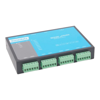
- Page 4 Network management relative principle overview The description of this manual is from the NP318T-8DI (3IN1). Other types of products in addition to the support of the serial port type (RS-232, RS-422, RS-485), the number of serial ports and the number of network ports are different, the interface functions and operations are the same.
-
Page 5: Revision History
The tips of configuration and operation. Pay attention to the operation or information to ensure success device configuration or normal working. Revision History Version No. Date Revision note 2017-05-25 Layout Adjustment 2017-10-10 Add Password Verification Funciton 3onedata proprietary and confidential Copyright © 3onedata Co., Ltd. -
Page 6: Table Of Contents
EBOOT MONITORING STATE ......................39 ......................39 BOUT HAPTER ......................39 ONNECT TATE COM S ......................40 TATE COM P ..................... 41 ARAMETER CONTROLING ACCESS ...................... 43 ......................43 BOUT HAPTER 3onedata proprietary and confidential Copyright © 3onedata Co., Ltd. - Page 7 ..................... 85 UDP M ..................... 91 ULTICAST PART TWO: FREQUENTLY ASKED QUESTIONS ..............97 FAQ ............................97 ......................97 BOUT HAPTER 10.1 ....................... 97 OGIN ROBLEM 10.2 ..................98 ONFIGURATION ROBLEM 3onedata proprietary and confidential Copyright © 3onedata Co., Ltd.
-
Page 8: Preface
1.2 Set the IP address of the Computer The default management of the serial device server is as follows: IP Settings Default Values IP address 192.168.1.254 Subnet mask 255.255.255.0 When configuring a serial server through the Web: 3onedata proprietary and confidential Copyright © 3onedata Co., Ltd. - Page 9 Step 1 Open “Control panel > Network connection > Local area connection > Properties > Internet protocol version (TCP/IPv4) Properties”. Step 2 Change the "5" selected by the red frame in the figure to "1". Step 3 Click "OK". Step 4 End. 3onedata proprietary and confidential Copyright © 3onedata Co., Ltd.
-
Page 10: Login The Web Configuration Interface
After successful login, you can configure the relevant parameters and information of the WEB interface as needed. Note: After logging in to the device, you can modify the IP address of the serial server for ease of use. 3onedata proprietary and confidential Copyright © 3onedata Co., Ltd. -
Page 11: Web Timeout Processing
Keep the configuration of this login; Logout this login Note: After the system times out, if you need to continue operate in the WEB interface, please re-login. 3onedata proprietary and confidential Copyright © 3onedata Co., Ltd. -
Page 12: Device Information
Display device name. Module Display device module. Description Displays the number of network ports Serial NO. Display device serial number. Default LAN Display the default network port. Hardware Ver. Display device hardware version. 3onedata proprietary and confidential Copyright © 3onedata Co., Ltd. - Page 13 Display device gets the way for DNS. MAC address Display device MAC address. IP address Display deivce IP address information. Gateway Display device gateway address. DNS server Display device DNS server address. 3onedata proprietary and confidential Copyright © 3onedata Co., Ltd.
-
Page 14: Setting Network
Operation Path Open “Network Settings> Network Settings” in sequence. Interface description Network settings interface screenshot The dual-port device displays the "Lan1" and "Lan2" columns. The single-port device displays only the "Lan1" column. 3onedata proprietary and confidential Copyright © 3onedata Co., Ltd. - Page 15 Single-port devices do not support this function。 Lan1 Network port 1 network configuration column. Note: The default IP for Lan1 is 192.168.1.254. Use the following IP addresses: Manually configure the The way to get the 3onedata proprietary and confidential Copyright © 3onedata Co., Ltd.
-
Page 16: Ip Address
IP address. When the dynamic IP address changes, the serial server reports its own IP address to the user by intermittently, so that the user knows the new IP address of the serial server in time. 3onedata proprietary and confidential Copyright © 3onedata Co., Ltd. -
Page 17: Serial Server
FIFO function, RTS control, DTR control and Packing length and other advanced parameter information. Operation Path Open “serial server > COM settings” in sequence. Interface Description COM settings interface screenshot 3onedata proprietary and confidential Copyright © 3onedata Co., Ltd. - Page 18 5 bits 6 bits 7 bits 8 bits StopBits Select the stop bit for the corresponding serial number. The options are: 1 bits 2 bits 3onedata proprietary and confidential Copyright © 3onedata Co., Ltd.
- Page 19 0 ~ 1460. When the frame length is 0, it indicates that the data transmission length is not limited. Note: Actual pack length exists a small amount of deviation to the 3onedata proprietary and confidential Copyright © 3onedata Co., Ltd.
-
Page 20: Checking Com Information
On the "COM Information" page, you can view parameter information such as serial number, alias, baud rate, data bit, stop bit, parity bit and flow control. Operation Path Open "Serial server> COM Information" in sequence. 3onedata proprietary and confidential Copyright © 3onedata Co., Ltd. -
Page 21: Com Mode Settings
The serial server support the working modes such as: RealCom mode, TCP server mode, TCP client mode, UDP server mode, UDP client mode, Pair mode, UDP rang mode, and UDP multicast mode. Operation Path Open in sequence: "Serial Server>COM Mode Settings". 3onedata proprietary and confidential Copyright © 3onedata Co., Ltd. -
Page 22: Realcom Mode
TCP / IP packet and analyse the packet, and after unpacking send the original data to the serial device through the corresponding serial port, and vice versa. Interface Description RealCom Mode interface screenshot 3onedata proprietary and confidential Copyright © 3onedata Co., Ltd. - Page 23 Cmd type Compatible with other companies of the virtual serial port software. The options are: Disable: means to use our company's virtual serial port 3onedata proprietary and confidential Copyright © 3onedata Co., Ltd.
- Page 24 "COM parameter" option under "state monitor". The queue access mode is a question-and-answer communication mode to ensure that the communication is normal. 3onedata proprietary and confidential Copyright © 3onedata Co., Ltd.
-
Page 25: Tcp Server Mode
The TCP server mode supports up to four session connections simultaneously, allowing multiple hosts to simultaneously read or send Ethernet data to a serial device. Interface Description TCP server mode interface screenshot 3onedata proprietary and confidential Copyright © 3onedata Co., Ltd. - Page 26 Send_msg The information sent after the device is connected to the peer client. The options are: Ipaddr: After the connection is successful, send the IP 3onedata proprietary and confidential Copyright © 3onedata Co., Ltd.
- Page 27 Disabled: If the network connection is blocked or the response is lost, the system will wait until the data is successfully sent to all network connections before 3onedata proprietary and confidential Copyright © 3onedata Co., Ltd.
- Page 28 This approach is very effective in reducing latency and improving product performance. Apply to all port Check the “Apply to all port” check box to apply the current settings to all serial ports. 3onedata proprietary and confidential Copyright © 3onedata Co., Ltd.
-
Page 29: Tcp Client Mode
Similarly, TCP client mode can support up to four session connections at the same time, so that multiple hosts can simultaneously read or send Ethernet data to a serial device. Interface Description TCP Client mode interface screenshot 3onedata proprietary and confidential Copyright © 3onedata Co., Ltd. - Page 30 After the password is verified, the server can communicate with the device . The options are: Enable: Enable password verification function. Disable: Disable password verification function. 3onedata proprietary and confidential Copyright © 3onedata Co., Ltd.
- Page 31 Idle: If the idle timeout time is greater than 0, the system will automatically shut down TCP connections that do not have any data send and receive activity for a 3onedata proprietary and confidential Copyright © 3onedata Co., Ltd.
- Page 32 How long to allow the serial server to respond to each host's request, the specified time after the arrival of the serial server and the host that the communication is complete, 3onedata proprietary and confidential Copyright © 3onedata Co., Ltd.
-
Page 33: Udp Server Mode
The TCP timeout takes effect only when "Disconnect control" is set to "idle". 4.3.4 UDP Server Mode In UDP server mode, the serial server through the UDP protocol and user-specified host for serial data transmission. UDP mode serial device server can transfer data 3onedata proprietary and confidential Copyright © 3onedata Co., Ltd. - Page 34 Normal communication does not allow other hosts and serial servers to communicate data. Once the TCP timeout is met, the current IP address and port are released, allowing other hosts and serial servers to communicate. 3onedata proprietary and confidential Copyright © 3onedata Co., Ltd.
- Page 35 This approach is very effective in reducing latency and improving product performance. Apply to all port Check the “Apply to all port” check box to apply the current settings to all serial ports. 3onedata proprietary and confidential Copyright © 3onedata Co., Ltd.
-
Page 36: Udp Client Mode
Compared with TCP mode, UDP protocol is faster and more efficient. Interface Description UDP Client mode interface screenshot 3onedata proprietary and confidential Copyright © 3onedata Co., Ltd. - Page 37 Disabled: Means that queue access mode is not enabled. Response timeout Time interval that allows the serial server to respond to each host's request, the communication between serial server 3onedata proprietary and confidential Copyright © 3onedata Co., Ltd.
-
Page 38: Pair Slave & Master Mode
The two serial servers in this mode establish a network connection with each other via Ethernet and transparently transmit data from the respective serial port to each other. 3onedata proprietary and confidential Copyright © 3onedata Co., Ltd. - Page 39 Applied to the pair salve mode, that is, the destination port of the pair master mode device. Dest Address Applied to the pair master mode, that is, the IP address of the pair slave mode device. 3onedata proprietary and confidential Copyright © 3onedata Co., Ltd.
-
Page 40: Udp Rang Mode
UDP port mode serial device can also receive data from one or more hosts. 3onedata proprietary and confidential Copyright © 3onedata Co., Ltd. - Page 41 UDP data. Apply to all port Check the “Apply to all port” check box to apply the current settings to all serial ports. 3onedata proprietary and confidential Copyright © 3onedata Co., Ltd.
-
Page 42: Udp Multicast Mode
UDP protocol, and can also receive unicast or multicast data from one or more devices, enabling multipoint-to-multipoint communication. Interface Description UDP multicast mode interface screenshot 3onedata proprietary and confidential Copyright © 3onedata Co., Ltd. - Page 43 The multicast address ranges from 224.0.0.0 to 239.255.255.255. The device can send or receive multicast data to multiple hosts. Listen port The network receives the listening port of UDP data. The 3onedata proprietary and confidential Copyright © 3onedata Co., Ltd.
-
Page 44: Com Mode Information
4.5 Reboot Port Function Description On the “Reboot Port” page, you can reboot the corresponding serial port of the device as needed. Operation Path Open in sequence: "Serial server> Reboot port". 3onedata proprietary and confidential Copyright © 3onedata Co., Ltd. - Page 45 Check the "Reboot port" check box, which restart the device corresponding serial port. The port restart will disconnect the corresponding serial port and Ethernet connection, serial communication will also be interrupted, the transmission of communication data may be lost. 3onedata proprietary and confidential Copyright © 3onedata Co., Ltd.
-
Page 46: Monitoring State
On the “Connect State” page, you can view the working mode and connect state of the device's serial port number. Operation Path Open in sequence: “State Monitor> Connect State” Interface Description Connect state interface screenshot 3onedata proprietary and confidential Copyright © 3onedata Co., Ltd. -
Page 47: Com State
Serial status interface main element configuration instructions Interface Elements Description Port Display the serial number of the device. TX,RX,TX Total,RX Total Display the data transceiver status of the corresponding serial port. 3onedata proprietary and confidential Copyright © 3onedata Co., Ltd. -
Page 48: Com Parameter
PairtyBits Displays the parity bits of the serial port corresponding to the device. Flow Control Display whether or not flow control is enabled on the serial port of the device. 3onedata proprietary and confidential Copyright © 3onedata Co., Ltd. - Page 49 User Manual 3onedata proprietary and confidential Copyright © 3onedata Co., Ltd.
-
Page 50: Controling Access
On the “Device Security” page, you can enable or disable Web console, Telnet console, device search and firmware upgrade functions. Operation Path Open in sequence: “Access Ctrl> Device Security”. Interface Description Device security interface screenshot 3onedata proprietary and confidential Copyright © 3onedata Co., Ltd. -
Page 51: Ip Filter
On the “IP Filter” page, you can restrict access to host IP addresses and subnet masks to be accessed or connected by setting access rules. Operation Path Open in sequence: "Access Ctrl> IP Filter". 3onedata proprietary and confidential Copyright © 3onedata Co., Ltd. - Page 52 Forbidden: Disable access to your set IP address and subnet mask. IP Address address within filtering rule, example “192.168.1.61”. Subnet Mask Set subnet mask within filtering rule, for example “255.255.255.0”. 3onedata proprietary and confidential Copyright © 3onedata Co., Ltd.
-
Page 53: Mac Filter
Enables or disables MAC address filtering rules Filtering Rule Set the access rights of the system beyond the MAC address of the filtering rule number 1~16. Number Display MAC address of the filterin g rule 3onedata proprietary and confidential Copyright © 3onedata Co., Ltd. -
Page 54: User Manage
User manage interface Main element configuration instructions Interface Elements Description Authentication Enable or disable authentication function Number Displays the user number. User Name Displays the user name of the login WEB configuration 3onedata proprietary and confidential Copyright © 3onedata Co., Ltd. - Page 55 Please remember the revised user name and password, if accidentally forgotten, please restore the factory settings through the WEB interface, the default login WEB configuration interface user name and password are "admin". 3onedata proprietary and confidential Copyright © 3onedata Co., Ltd.
-
Page 56: Remote Monitor
7.1.2 Work Mechanism of SNMP 3onedata proprietary and confidential Copyright © 3onedata Co., Ltd. -
Page 57: Snmp Version
NMS and the agent. If the community name set by the NMS is different from the community name set on the managed device, the NMS and the agent can not establish an SNMP connection, causing the NMS to fail to access the agent. The 3onedata proprietary and confidential Copyright © 3onedata Co., Ltd. - Page 58 Enable or disable SNMP settings function Read only Configure read-only SNMP community names with Get community permission only. Read/write Configure read and write SNMP community names with Get community and Set operations. 3onedata proprietary and confidential Copyright © 3onedata Co., Ltd.
-
Page 59: System Manage
IP mapping table does not limit incoming data; the forwarding data port is the corresponding LAN port in the mapping table from the network segment to which the destination address belongs 3onedata proprietary and confidential Copyright © 3onedata Co., Ltd. -
Page 60: System Information
8.2 System Information Function Description On the “System Info” page, you can configure the device module, name, description, serial number, and contact information. Operation Path Open in sequence: "System Manage> System Info". 3onedata proprietary and confidential Copyright © 3onedata Co., Ltd. - Page 61 Enter the device number in the “Serial NO.” text box. Describe the location of the device installation, no more than 30 bytes. Contact information Enter the contact information of the equipment maintenance personnel in the "Contact information" text box. 3onedata proprietary and confidential Copyright © 3onedata Co., Ltd.
-
Page 62: System File
Click "Start" to restore the serial server to the factory Default configuration. Download Click "Download" to download the current configuration file Configration for the serial server. Upload Click "Choose File", select the profile you are ready, click 3onedata proprietary and confidential Copyright © 3onedata Co., Ltd. -
Page 63: Logout & Reboot
On the “Logout & Reboot” page, you can log off and reboot the serial server system. Operation Path Open in sequence: "System Manage > Logout & Reboot". Interface Description Logout & Reboot interface screenshot 3onedata proprietary and confidential Copyright © 3onedata Co., Ltd. - Page 64 Click "Start" and the system will log out and jump to the initial login screen. Reboot System Click "reboot" in the pop-up dialog box, click "OK" to complete the system reboot. 3onedata proprietary and confidential Copyright © 3onedata Co., Ltd.
-
Page 65: Working Mode Configuration Example
COM2 in the management software VSP Manager. The serial port information is as follows: BaudRate: 115200 PairtyBits: None DataBits: 8 StopBits: 1 3onedata proprietary and confidential Copyright © 3onedata Co., Ltd. -
Page 66: Operation Steps
Mask" and "Gateway address" corresponding to the serial server. 3. Other parameters remain the default, click "submit". Setp 2 Configure the serial port parameter information. 1. Log in to the Web configuration interface and select "Serial Server> COM Settings". 3onedata proprietary and confidential Copyright © 3onedata Co., Ltd. - Page 67 5. Other parameters remain the default, click "Submit". Setp 3 Configure the working mode of the serial server. 1. Log in to the Web configuration interface and select "Serial Server> COM Mode Settings". 3onedata proprietary and confidential Copyright © 3onedata Co., Ltd.
- Page 68 "Add Device". Enter the IP address and subnet mask of the serial server and click “OK”. 2. Right click "192.168.1.250" and select "Quick Add Ports". After creating the virtual serial port COM2, click “OK”. 3onedata proprietary and confidential Copyright © 3onedata Co., Ltd.
- Page 69 Step 5 Run the "ComTest3One" software, test the real serial port COM1 and virtual COM2 communicate with each other. 1. Install and run the “ComTest3One” software, click "Begin" menu "New Windows". 2. Add the real serial "COM1" and virtual serial "COM2" two windows, the "COM1" 3onedata proprietary and confidential Copyright © 3onedata Co., Ltd.
- Page 70 3. Respectively, open the "COM1" and "COM2" serial port signal, check the "automatic send" check box, test and see the real serial port COM1 and virtual COM2 between the data transceiver status. 3onedata proprietary and confidential Copyright © 3onedata Co., Ltd.
-
Page 71: Tcp Server Mode
The parameters of the host PC (TCP client) are as follows: IP Address: 192.168.1.61 Operation steps Setp 1 Configure the IP address of the serial server. 1. Log in to the Web configuration interface and select "Network Setting". 3onedata proprietary and confidential Copyright © 3onedata Co., Ltd. - Page 72 3. Set the "BaudRate", "DataBits", "StopBits" and "ParityBits" in the "Settings" option box. 4. Other parameters remain the default, click "submit". Step 3 Configure the working mode of the serial server. 3onedata proprietary and confidential Copyright © 3onedata Co., Ltd.
- Page 73 2. In the "Local IP" drop-down list box, select the IP address "192.168.1.61" of the host PC (that is, the TCP client). 3. In the "Device IP" text box, enter the IP address "192.168.1.250" of the serial server 3onedata proprietary and confidential Copyright © 3onedata Co., Ltd.
- Page 74 5. Select the TcpClient connection you created and click “Start”. Step 5 Synchronize the operation of the "ComTest3One" and "DebugTool" software, test the serial server (TCP server) and the host PC (TCP client) to communicate with each other. 3onedata proprietary and confidential Copyright © 3onedata Co., Ltd.
- Page 75 4. Run the "DebugTool" software, in the TcpClient option box to view the host PC to receive the serial information. Similarly, the host PC can also send information to the serial device. 3onedata proprietary and confidential Copyright © 3onedata Co., Ltd.
-
Page 76: Tcp Client Mode
IP Address: 192.168.1.61 Local Port: 31000 Operation steps Setp 1 Configure the IP address of the serial server. 1. Log in to the Web configuration interface and select “Network Setting”. 3onedata proprietary and confidential Copyright © 3onedata Co., Ltd. - Page 77 2. Log in to the Web configuration interface and select “Serial Server> COM Settings”. 3. Select “COM1” in the “Port” drop-down list. 4. Set the "BaudRate", "DataBits", "StopBits" and "ParityBits" in the "Settings" option box. 5. Other parameters remain the default, click “submit”. 3onedata proprietary and confidential Copyright © 3onedata Co., Ltd.
- Page 78 Step 4 Run the "DebugTool" software, for the host to create TCP server. 1. To install and run "DebugTool" Software, click “Create Connection” drop-down list box and choose “Create Network Debugging> TcpServer”. 3onedata proprietary and confidential Copyright © 3onedata Co., Ltd.
- Page 79 3. In the "Local Port" text box, enter the local port "31000" of the host PC (that is, the TCP server) and click "OK". 4. Select the TcpServer connection you created and click “Start”. Step 5 Simultaneous operation of the "DebugTool" and "ComTest3One" software, test the 3onedata proprietary and confidential Copyright © 3onedata Co., Ltd.
- Page 80 4. Run the "DebugTool" software, in the TcpServer option box to see the host PC to receive the serial information. Similarly, the host PC can also send information to the serial device. 3onedata proprietary and confidential Copyright © 3onedata Co., Ltd.
-
Page 81: Udp Server Mode
IP Address: 192.168.1.61 Local Port: 31000 Operation steps Setp 1 Configure the IP address of the serial server. 1. Log in to the Web configuration interface and select “Network Setting”. 3onedata proprietary and confidential Copyright © 3onedata Co., Ltd. - Page 82 3. Set the “BaudRate”, “DataBits”, “StopBits” and “ParityBits” in the “Settings” option box. 4. Other parameters remain the default, click “Submit”. Setp 3 Configure the working mode of the serial server. 3onedata proprietary and confidential Copyright © 3onedata Co., Ltd.
- Page 83 2. In the "Local IP" drop-down list box, select the IP address "192.168.1.61" of the host PC (that is, the Udp client). 3. Enter the port number "31000" for the host PC (that is, the Udp client) in the "Local Port" text box. 3onedata proprietary and confidential Copyright © 3onedata Co., Ltd.
- Page 84 Step 5 Simultaneous operation of the "DebugTool" and "ComTest3One" software, test the serial server (UDP server) and the host PC (UDP client) to communicate with each other. 1. Install and run the “ComTest3One” software, click “Begin” menu “New Windows”. 3onedata proprietary and confidential Copyright © 3onedata Co., Ltd.
- Page 85 4. Run the "DebugTool" software, in the Udpclient option box to see the host PC to receive the serial information. Similarly, the host PC can also send information to the serial device. 3onedata proprietary and confidential Copyright © 3onedata Co., Ltd.
-
Page 86: Udp Client Mode
Mask" and "Gateway address" corresponding to the serial server. 3. Other parameters remain the default, click “submit”. Setp 2 Configure the serial port parameter information. 1. Log in to the Web configuration interface and select “Serial Server> COM Settings”. 3onedata proprietary and confidential Copyright © 3onedata Co., Ltd. - Page 87 6. Enter the local port number "31000" of the host PC in the "Dest port" text box. 7. Enter the local port number "30000" of the serial server in the "Listen port" text box. 8. Other parameters remain the default, click “submit”. 3onedata proprietary and confidential Copyright © 3onedata Co., Ltd.
- Page 88 PC (that is, the UDP server). 3. In the “Local Port” text box, enter the local port "31000" for the host PC (that is, the UDP server) and click “OK”. 3onedata proprietary and confidential Copyright © 3onedata Co., Ltd.
- Page 89 2. Add serial port “COM1” window, configure the COM, BaudRate, parity, DataBits and other parameters and WEB interface “COM settings” consistent. 3. Open the “COM1” serial port signal, for example, enter the serial information “0123456789AB”, and click “Manual Send”. 3onedata proprietary and confidential Copyright © 3onedata Co., Ltd.
-
Page 90: Pair Slave & Master Mode
The serial device server B uses the pair master mode to actively connect the serial device server A. Serial device server A and serial device server B with their own computer connected to the serial port are "COM1". 3onedata proprietary and confidential Copyright © 3onedata Co., Ltd. - Page 91 Setp 3 Click the “Work Mode” drop-down list box and select “Pair Master Mode”. Setp 4 Enter the IP address "192.168.1.254" of the serial device server A in the "Dest Address" text box. 3onedata proprietary and confidential Copyright © 3onedata Co., Ltd.
-
Page 92: Udp Rang Mode
IP Address: 192.168.1.62 Local Port: 31000 Operation steps Setp 1 Configure the IP address of the serial server. 1. Log in to the Web configuration interface and select “Network Setting”. 3onedata proprietary and confidential Copyright © 3onedata Co., Ltd. - Page 93 3. Set the “BaudRate”, “DataBits”, “StopBits” and “ParityBits” in the “Settings” option box. 4. Other parameters remain the default, click “Submit”. Setp 3 Configure the working mode of the serial server. 3onedata proprietary and confidential Copyright © 3onedata Co., Ltd.
- Page 94 1. To install and run "DebugTool" Software, click “Create Connection” drop-down list box and choose “Create Network Debugging> UdpClient”. 2. In the “Monitoring IP” drop-down list box, select the IP address "192.168.1.61" of 3onedata proprietary and confidential Copyright © 3onedata Co., Ltd.
- Page 95 Setp 5 Run the "DebugTool" software in the host B to create UDP client B. 1. To install and run "DebugTool" Software, click “Create Connection” drop-down list box and choose “Create Network Debugging> UdpClient”. 3onedata proprietary and confidential Copyright © 3onedata Co., Ltd.
- Page 96 4. Enter the IP address "192.168.1.250" of the serial server (that is, the Udp server) in the "Remote IP" text box. 5. In the “Remote Port” text box, enter the port number “30000” for the serial server (that is, the Udp server), and click “OK”. 3onedata proprietary and confidential Copyright © 3onedata Co., Ltd.
- Page 97 4. Run the "DebugTool" software, in the UdpClient option box to view the host A and host B received the serial information. Similarly, host A and host B can also send information to the serial device. 3onedata proprietary and confidential Copyright © 3onedata Co., Ltd.
-
Page 98: Udp Multicast Mode
UDP protocol can make the serial device data through unicast or multicast sent to one or more hosts, but also can receive from one or more host unicast or multicast data, complete multipoint-to-multipoint communication. 3onedata proprietary and confidential Copyright © 3onedata Co., Ltd. - Page 99 Mask" and "Gateway address" corresponding to the serial server. 3. Other parameters remain the default, click “submit”. Setp 2 Configure the serial port parameter information. 1. Log in to the Web configuration interface and select “Serial Server> COM Settings”. 3onedata proprietary and confidential Copyright © 3onedata Co., Ltd.
- Page 100 8. Enter the group address "239.0.0.0" of the host PC in the "Group Address/ Group 1" text box. 9. Enter the local port unmber "30000" of the serial server in the "Listen port" text box. 10. Other parameters remain the default, click “submit”. 3onedata proprietary and confidential Copyright © 3onedata Co., Ltd.
- Page 101 4. In the “Remote IP” text box, enter the IP address "239.0.0.0" for the serial device server. 5. In the “Remote Port” text box, enter the local port number "30000" for the serial 3onedata proprietary and confidential Copyright © 3onedata Co., Ltd.
- Page 102 “0123456789AB”, and click “Manual Send”. 4. Run the "DebugTool" software, in the UdpGroup option box to view the host received the serial information. Similarly, host can also send information to the serial device. 3onedata proprietary and confidential Copyright © 3onedata Co., Ltd.
- Page 103 User Manual 3onedata proprietary and confidential Copyright © 3onedata Co., Ltd.
-
Page 104: Part Two: Frequently Asked Questions
The initial user name and password are "admin". Is it equivalent to configure the device through between the web browser and the management software? Both configurations are the same and do not conflict. 3onedata proprietary and confidential Copyright © Shenzhen 3onedata Technology Co., Ltd. -
Page 105: Configuration Problem
Exclamation mark or the computer and serial server can be changed to the same network segment. Serial server link LED does not light? Fault detection: The serial server is not powered on. 3onedata proprietary and confidential Copyright © Shenzhen 3onedata Technology Co., Ltd. - Page 106 IP address and port number of the remote virtual serial device and the serial server are consistent. Test the serial server with test software found garbled? 3onedata proprietary and confidential Copyright © Shenzhen 3onedata Technology Co., Ltd.
- Page 107 Can support up to four computer communications, as long as the open multi-session connection can be. 12. When the two computers correspond to a virtual serial port, will the communication be intermittent? 3onedata proprietary and confidential Copyright © Shenzhen 3onedata Technology Co., Ltd.
- Page 108 The conventional serial server supports 32 devices and can also customize 64,128 nodes. 19. After configuring the serial server parameters, found that these parameters can not be saved? 3onedata proprietary and confidential Copyright © Shenzhen 3onedata Technology Co., Ltd.
- Page 109 Will be connected to the same serial port with the host LAN (with the network segment, with the Vlan, with the broadcast domain), use the management software to search the device, view the device IP address. 3onedata proprietary and confidential Copyright © Shenzhen 3onedata Technology Co., Ltd.
- Page 110 (virtual serial port / serial port server). Access terminal serial equipment (attendance, access control, etc.), the use of data acquisition and management software to test whether the normal communication connection. 3onedata proprietary and confidential Copyright © Shenzhen 3onedata Technology Co., Ltd.
- Page 111 User Manual Shenzhen 3onedata Technology Co., Ltd. Address: 3/B, Zone 1, Baiwangxin High Technology Industrial park, Nanshan District, Shenzhen, 518108 China Tel: +86-755-26702668 E-mail: sales@3onedata.com Fax: +86-755-26703485 Website: http://www.3onedata.com 3onedata proprietary and confidential Copyright © 3onedata Co., Ltd.
Need help?
Do you have a question about the NP318T-8DI and is the answer not in the manual?
Questions and answers