
Related Manuals for Samson TROVIS 6495 Series


Summary of Contents for Samson TROVIS 6495 Series
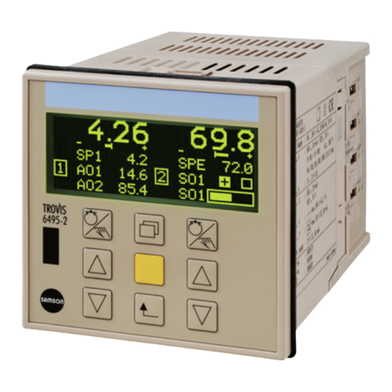
- Page 1 Series 6495 Industrial Controller TROVIS 6495-2 Mounting and Operating Instructions EB 6495-2 EN Firmware version 1.11 ® Edition December 2009 Electronics from SAMSON...
- Page 2 Definitions of the signal words used in these instructions DANGER! NOTICE DANGER indicates a hazardous situation NOTICE indicates a property damage mes- which, if not avoided, will result in death or sage. serious injury. Note: Supplementary explanations, informa- tion and tips EB 6495-2 EN...
-
Page 3: Table Of Contents
Contents Contents Page Important safety instructions ..... . 5 Device version ......6 Article code . - Page 4 13.3 SAMSON memory pen ......53 Setting and operation with TROVIS-VIEW software ..55 14.1...
-
Page 5: Important Safety Instructions
Important safety instructions Important safety instructions For your own safety, follow these instructions concerning the mounting, start-up and opera- tion of the industrial controller: The industrial controller may only be mounted, started up or operated by trained and experienced personnel familiar with the product. According to these Mounting and Operating Instructions, trained personnel refers to individuals who are able to judge the work they are assigned to and recognize possi- ble dangers due to their specialized training, their knowledge and experience as well... -
Page 6: Device Version
Device version Device version Article code Industrial Controller TROVIS 6495-2 x Supply voltage 85 to 264 V AC 24 V AC/DC Accessories Accessories Order no. TROVIS-VIEW Configuration and Operator Interface..6661-1033 Infrared adapter (RS-232)..8864-0900 Bracket for infrared adapter... 1400-9769 USB 1.1 serial adapter... -
Page 7: Installation
Installation 1. Prepare a panel cut-out with the dimen- Installation sions 92 +0.8 x 92 +0.8 The TROVIS 6495-2 Industrial Controller is 2. Push the industrial controller into the designed for panel mounting. Its front case panel cut-out from the front. has the dimensions 96 x 96 mm. -
Page 8: Electrical Connection
Electrical connection rators providing a good ground connec- Electrical connection tion. The controller has screw terminals for Risk of electric shock! 1.5 mm² wires (0.5 to 1.5 mm² wire When installing electric cables, you are re- cross-section). quired to observe the regulations governing electrical power plant installation in the The lines are connected to the terminal strips country where the controller is to be in-... - Page 9 Electrical connection Generally, we recommend performing a Potentiometer user calibration. To perform a calibration, The analog input AI2 is designed for the use the configuration items A.20.2.13 connection of a potentiometer. Potentiome- (zero) and A.20.2.14 (end), see section ters between 50 and 1200 Ω can be connected.
- Page 10 Electrical connection Terminal strip 2 Current Voltage Digital input Digital input with internal supply with external supply 0/4 to 20 mA 0/2 to 10 V Supply output – 21 V DC max. 90 mA – Analog output AO1 – Digital input DI1 24 V DC –...
- Page 11 Electrical connection Terminal strip 3 Supply 3 to 42 V DC, max. 30 mA – Digital output DO5 – Digital output DO6 – Digital output DO7 Terminal strip 4 Supply voltage 85 to 264 V AC 24 V AC/DC (20 to 30 V) L–...
-
Page 12: Operation
Operation Operation Operation structure Operating menu: The operating menu allows the control pa- The controller has the following operation rameter and set points to be changed. These levels: are located in two different menu items. Operating level (Fig. 3): Configuration menu: The controller is in this level while the con- The controller is adapted to its control task troller is in operation. -
Page 13: Display And Operator Controls
Operation To make the initial setting effective, both DIP Display and operator switches of an analog input must have the controls same position. If just one DIP switch is switched, the last valid configuration of the Display input remains effective. An error message is The controller is in the operating level while generated and the digital output for error the controller is in operation. - Page 14 Operation The function of the keys varies depending on Note: A difference is only made between the level/menu which is active. See the table the keys on the left and right in the operat- below. ing level. In this case, the keys on the left are used to operate the controller on the left dis- play and the keys on the right are used to operate the controller on the right display.
-
Page 15: Operating Level
Operating level The display in the operating level is ar- Operating level ranged depending on the control mode se- The operating level is active while the con- lected. For control modes with two control- troller is in operation. Key information on lers, the default display has two sections: the control process is displayed in this level. -
Page 16: Changing The Set Point
Operating level Overview: Default reading on display in the operating level for various control modes Control mode Operating level (default reading) M.1-5 Fixed set Controller [1] Controller [2] point/follow-up control M.1-6 Ratio controller [1] Controller [2] Ratio controller and controller To operate the controller, use the cursor keys Changing the set point ) and the manual/automatic key... -
Page 17: Opening/Closing Cascade
Operating level Note: In the following example, the master controller [2] is shown on the right display (default). As a result, the manual/automatic key on the right is used to open/close the cascade. 1x Switch to manual mode. 1x Close the cascade. The hand icon appears above the controller designation [1]/[2]. - Page 18 Info menu ← ← ← ---------------------- ---------------------------- → → → Operating level Info menu Controller [1] * Set point Input variable PV, … ** Output ** Controller [2] See controller [1] If an error message exists, a submenu is added to the info menu.
-
Page 19: Info Menu
Info menu Enter the info menu Info menu 1x Change to the info menu. Information on the running process and the controller can be viewed in the info menu. Usually, there are the following menu items Controller [1], possibly Controller [2], Inputs/outputs, Last events, Diagno- sis and Versions. - Page 20 Info menu Notes concerning the readings in the info menu • Menu item Inputs/outputs Directly after the digital inputs and outputs, the state of the input/output is indicated: (0) or (1) In the case of a reversed digital input or output, the state of the input/output in reversed form is additionally indicated: inv.(1) or inv.(0) The controller assigned to the input/output is indi- cated on the right of the display ([1] or [2]) in the...
- Page 21 Info menu • Menu item Diagnosis - 1 Operating time indicates the time the controller has been operating since the last start-up of the controller in days.hours:Minutes:Seconds. The total operating time refers to how long the controller has been supplied with voltage (Days.Hours:Minutes:Seconds).
- Page 22 Operating menu ← ← ← ← ------------------- --------------------- ---------------------------------- → → → → ↵ Operating level Op. menu Control (proportional-action Controller [1] parameters coefficient) Change control Op. menu parameters (reset time) Controller [2] See section 8.2 (derivative-action time) (operating point) TV.K (derivative-action gain TV.K1) 1.P+...
-
Page 23: Operating Menu
Operating menu Enter the operating menu of Controller [1] Operating menu 1x Switch to the main menu. The operating menu consists of the menu items Control parameters and Set point. The following actions can be per- formed: Change control parameters → Section 8.2 Operating menu contr. - Page 24 Operating menu to 100 % range of the measuring Assignment between control parameters and range is plotted on the right. control behavior The current value of the propor- tional-action coefficient KP is indi- C.3.1.1 cated below. • • • • •...
-
Page 25: Switching Over Internal/External Set Point
Operating menu The current set point is high- Switching over lighted: SPE internal/external set point If the external set point SPE (C.2.1.2-1) is configured, the set point SP is equal to SPE. The switchover to an internal set point SPI is 1x Select internal set point SPI. - Page 26 Operating menu 1x Activate the menu item Set point Required configuration for determining the set point C.2.1.1-1/-2/-3/-4 C.2.1.1-2/-3/-4 C.2.1.1-3/-4 The actual value at the comparator C.2.1.1-4 PV0 ( ), the set point at the com- parator SP0 ( ) and the manipu- lated variable Y ( ) are indicated Example: The controller [1] has two internal...
- Page 27 Operating menu The set point SP1 has the required value of 70.0 and therefore does not need to be changed. 1x Select the set point SP2. 1x Activate the set point setting SP2. The current set point is highlighted: 90.0 …...
- Page 28 Configuration level ← ← ← ------------------- ------------------------------------- → Configuring the controller, see section 9.2 Operating level Op. menu Controller [1] → → Configuration M Control mode Setting the control mode → I Input This menu contains the configura- tion of analog inputs AI1 to AI4 and digital inputs DI1 to DI4.
-
Page 29: Configuration Menu
Configuration menu 8. Set the operating direction, e.g. Configuration menu O.1.3-1 In the configuration menu, the controller is 9. Set the restart condition, e.g. C.4.1-0 adapted to its control task by changing indi- Configuration Manual KH 6495-2 EN con- vidual configuration items and parameters. tains further information. -
Page 30: Configuring The Controller
Configuration menu The menu M Control mode is highlighted. Configuring the controller The controller is configured by setting the configuration items and associated parame- ters. configuration item C.1.1.1 Input vari- Each configuration item has its own code, able PV: which gives information on its position in the configuration level. -
Page 31: Configuration Example
Configuration menu 1x Enter menu. 9.2.2 Configuration example The first submenu is highlighted. Based on a default setting (1x Fixed set … If the configuration item that you point/follow-up control M.1-1), the analog want to set is not in the highlighted input AI1 is to be set to Pt 1000. - Page 32 Configuration menu The controller is currently in the operating The input signal setting is high- level: lighted: Pt 100 1x Change setting to I.1.1-7 (Pt 1000). Enter the configuration level, see sec- tion 9.1. 1x Confirm new setting. Configure the input signal Set the measuring range 1x Select menu I Input.
-
Page 33: Adapting The Display
Configuration menu Return to the operating level Select type of Select signal representation 4x Return to the operating level. Row 1 C.5.1-1...4 – Row 2 C.5.2-1...2 – Row 3 C.5.3-1...3 – Row 4 C.5.4-1...41 C.5.5-1...6 Row 5 C.5.6-1...41 C.5.7-1...6 Adapting the display Example: Based on the default setting (1x The display can be adapted in the following fixed set point/follow-up controller M.1-1) - Page 34 Configuration menu 1x Enter menu 1C Controller [1]. 2x Change setting to 1C.5.6-2 (Output AO1). The submenu 1C.1 Input variables is highlighted. 1x Confirm setting. 4x Select submenu 1C.5 Controller Configure row representation display. 1x Select configuration item 1C.5.7 Row 5 representation. 1x Enter submenu 1C.5 Controller display.
-
Page 35: Setting Up Additional Display
Configuration menu To implement the additional display in the Return to the operating level display, it must be activated in the submenu 4x Return to the operating level. A.2 Operation display. The following table indicates the settings necessary to set up the additional display (see section 15.2 for details). - Page 36 Configuration menu Enter the configuration level, see sec- 1x Activate configuration item O.2.1. tion 9.1. The currently active setting is high- lighted: Off Assign source for Output AO2 1x Change setting to O.2.1-1 (Controller [1] output Y). 3x Select menu O Output. 1x Confirm setting.
- Page 37 Configuration menu 1x Activate menu item 1C.6. The currently active setting is dis- played: 1C.6.8-1 = Numerical 1x Activate configuration item 1C.6.8 Row 4 representation. The currently active setting is high- lighted: Numerical The configuration item 1C.6.1 Row 1x Change setting to 1C.6.8-2 1 is displayed with its currently ac- (Numerical, inverted).
-
Page 38: Switching Controller [1] And Controller [2] Displays
Configuration menu The submenu A.1 Language/ 1x Change setting to A.2.2-2 Sprache is highlighted. (Controller [1] additional reading). 1x Select submenu A.2 Operation display. 1x Confirm setting. Return to the operating level 1x Enter submenu A.2 Operation display. 4x Return to the operating level. The configuration item A.2.1 Left In the additional reading in the dis- display is displayed together with... - Page 39 Configuration menu and A.2.2 Right display must be 1x Select submenu A.2 Operation changed. display. Note: Before Controller [1] can be assigned to the right display, it must first be removed from the left display as one controller cannot be assigned to both displays at the same time.
- Page 40 Configuration menu 2x Change setting to A.2.1-3 Configure right display (Controller [2]). 1x Select configuration item A.2.2 Right display. 1x Confirm setting. 1x Activate configuration item A.2.2 Return to the operating level Right display. The currently active setting is high- 4x Return to the operating level.
-
Page 41: Locking The Controller
Locking the controller 1x Enter menu 1C Controller [1]. Locking the controller The submenu 1C.1 Input vari- It is possible to prevent unauthorized access ables is highlighted. to the controller. There are three ways to im- 6x Select submenu 1C.7 Operator plement the locking of the controller: keys. -
Page 42: Locking All Keys Over A Digital Input
Locking the controller 1x Activate menu A General set- Note: The operating menu Controller [1] is tings. not affected by the locking function. The set point can still be changed (see section 8.4). 10.2 Locking all keys over a digital input 2x Select submenu A.3 Operator The operator keys are locked when the se- keys. -
Page 43: Activating Key Number Operation
Locking the controller The operator keys are locked when Activate key number operation the digital input DI2 is active. Set- 5x (control modes with one controller) tings cannot be changed. 6x (control modes with two controllers) Select menu A General Settings. 10.3 Activating key number operation... - Page 44 Locking the controller 1x Change setting to A.4.1-1 (On). tion level can only be performed af- ter the key number has been entered using the cursor key ( ) and con- firmed by pressing the enter key 1x Confirm setting. Deactivate key number operation 1x Select Key number parameter.
-
Page 45: User Calibration
User calibration can be calibrated, the selection bar is User calibration displayed. The analog inputs and outputs are fac- Press the enter key ( ) to confirm the tory-calibrated. value. The end value is calibrated. A system-related user calibration can com- 11.2 Calibrating analog outputs pensate for long cables, small wire... -
Page 46: Fault Alarms
Fault alarms Incoming and outgoing error messages are Fault alarms time-stamped and saved in the last events The fault alarm icon is displayed when a list (info menu). fault alarm has been registered. The following error table contains possible causes and the recommended action. Note: We recommend for any errors not de- scribed in detail to switch off the power sup- ply and to wait approx. - Page 47 Check value analog input assigned to the controlled variable PV. Send controller back to Internal temperature sensor defective SAMSON AG for repair. Internal temperature Temperature too low (0 °C) Internal temperature The permissible ambient temper- • Check the ambient tempera- Temperature too high (60 °C)
-
Page 48: Interfaces
Interfaces Interfaces The TROVIS 6495-2 Controller is equipped with an infrared interace. In addition, it can be fitted with one of two optional interface boards. Data can be transferred between TROVIS-VIEW and the Controller over the interfaces. Refer to section 14.5. Infrared interface: Infrared adapter (RS-232) RS-232/USB interface board :... -
Page 49: Infrared Interface
Infrared interface The infrared interface can be accessed from the front of the controller. It is located above the SAMSON logo (Fig. 5). An infrared adapter is required for data transmission between the serial RS-232 port of the computer and the infrared interface integrated in the controller. A bracket ensures that the adapter is properly aligned. -
Page 50: Optional Interface Boards
Interfaces 13.2 Optional interface boards The controller can optionally be fitted with either a RS-232/USB interface board or a RS-485/USB interface board. These boards can be retrofitted. Installing the interface board The optional interface board is fitted at the back of the controller. 1. -
Page 51: Rs-485/Usb Interface Board
The driver is included on the TROVIS-VIEW CD-ROM (USB Driver > USB-RS232 Adapter 8812-2001) or can be downloaded from the Internet at www.samson.de > Services > Support & Downloads > USB driver. 13.2.2 RS-485/USB interface board To integrate the controller into a communications network, the controller can be fitted with an optional interface board RS-485 Modbus RTU (order no. - Page 52 The driver is included on the TROVIS-VIEW CD-ROM (USB Driver > USB-RS232 Adapter 8812-2001) or can be downloaded from the Internet at www.samson.de > Services > Support & Downloads > USB driver. Network structure Fig. 9 shows an example for the setup of an automation system with data exchange using Modbus protocol.
-
Page 53: Samson Memory Pen
Note: The memory pen can only be used when the controller is fitted with a RS-232/USB in- terface board. The SAMSON memory pen serves as a data carrier and is able to load and store data in its non-volatile memory. - Page 54 Interfaces The following display appears when data transmission is completed: The memory pen can be removed. EB 6495-2 EN...
-
Page 55: Setting And Operation With Trovis-View Software
Setting and operation with TROVIS-VIEW software 14.1 General The TROVIS-VIEW software allows various smart SAMSON devices to be configured over a common operator interface. It consists of the operator interface, communication server and the device-specific module. The software has a Windows ®... -
Page 56: Installing Trovis-View Software
2. Follow the on-screen prompts and instructions of the installation program. The TROVIS-VIEW Operator Interface can be used for different SAMSON devices. Note that the installation program also offers you the option of installing a demo module. To use the... -
Page 57: Starting Trovis-View And Performing Settings
Setting and operation with TROVIS-VIEW software 14.3 Starting TROVIS-VIEW and performing settings You can perform the settings in TROVIS-VIEW either when the device is connected (online) to the computer or not connected (offline). Refer to section 13. Note: When the device is not connected, the default settings appear on the operator inter- face or, alternatively, a stored TROVIS-VIEW file (*.tro) can be loaded and overwritten by selecting Open in the File menu. - Page 58 Setting and operation with TROVIS-VIEW software 3. In Options menu, select Language to change the interface language. Note: Unhighlighted languages are not available and cannot be selected. You can select a different language at any time. TROVIS-VIEW switches di- rectly to the selected language. 4.
- Page 59 Setting and operation with TROVIS-VIEW software Properties of data points are indicated by icons on clicking on a folder: Icon Meaning Data cannot be changed Data can be changed Software auxiliary data point (this data point exists only in TROVIS-VIEW and not in the controller) Data point can be executed Data point is user-defined Mark to indicate error...
-
Page 60: Configuring The Controller
Setting and operation with TROVIS-VIEW software 14.3.1 Configuring the controller Each menu in the configuration level of the controller has its own folder in TROVIS-VIEW, which contain further folders with the corresponding submenus. The configuration items and parameters are contained in these sunmenu folders. Refer to the configuration list (see sec- tion 15.2) to find the configuration items and parameters in TROVIS-VIEW. - Page 61 Setting and operation with TROVIS-VIEW software 3. Double-click on the value field to open the Modify Parameter window. 4. Select required setting and confirm by clicking the OK button. The new setting is adopted. Note: Right-click on a configuration item/parameter to open a context-sensitive menu with further options: –...
-
Page 62: Reading Information
Setting and operation with TROVIS-VIEW software 14.3.2 Reading information Information folder The Information folder contains information on the TROVIS 6495-2 Industrial Controller: Operation display folder The Operation display folder shows the inputs and outputs of the controller. The values for the analog inputs and set points can be entered. - Page 63 Setting and operation with TROVIS-VIEW software In addition, Set point at comparator SP0 , Actual value at comparator PV0 , Error signal e and Output Y of the controller can be read in this folder. Signals folder The values of individual signals can be monitored in the Signals folder. EB 6495-2 EN...
-
Page 64: Operational Data Graphs (Trend Viewer)
Setting and operation with TROVIS-VIEW software 14.4 Operational data graphs (Trend Viewer) The Trend Viewer displays graphs of the variables Set point at comparator SP0, Actual value at comparator PV0 and Output Y. In addition to the just displaying the data, logged data can also be saved to a file. 1. - Page 65 Setting and operation with TROVIS-VIEW software 2. If required, add new data points by dragging and dropping them from the Operation display folder into the Trend Viewer. 3. If required, you can edit the graph: Right-click the Trend Viewer. Select Edit from the context-sensitive menu.
-
Page 66: Data Transmission
Connect the serial port of the computer using the SAMSON connecting cable to the interface board of the controller. 2. Select Communications in Options menu to open the server settings win- dow. -
Page 67: Online Operation (Direct Data Transmission)
Setting and operation with TROVIS-VIEW software 14.5.2 Online operation (direct data transmission) The controller and TROVIS-VIEW are constantly connected in online operation. Current con- figuration and operating data are uploaded from the controller cyclically and displayed in TROVIS-VIEW. Likewise, any settings performed in TROVIS-VIEW are directly transferred to the controller. -
Page 68: Data Transmission Between Trovis-View And Memory Pen
Setting and operation with TROVIS-VIEW software 14.5.4 Data transmission between TROVIS-VIEW and memory pen 1. Plug memory pen (3) together with modular adapter (2) into the serial interface (COM port) of the computer (1). 2. Select Interface in Memory Pen menu. 3. -
Page 69: Appendix
Appendix Appendix 15.1 Technical data Inputs 4 analog inputs mA, V, Pt 100, Pt 1000, input 2 also for potentiometer Current or Version Differential input voltage Nominal signal range 0 to 20 mA, 4 to 20 mA, 0 to 10 V, 2 to 10 V inputs Resolution <... - Page 70 3 electrically isolated transistor outputs outputs External supply 3 to 42 V DC, max. 30 mA Interfaces Infrared Transmission protocol SAMSON-specific protocol (SSP) interface Data that can be Controller settings, processs variables, operating status transmitted Transmission rate 9600 bit/s Angle of deflection 50°...
- Page 71 (accessories) Connection USB: 5-pin mini-B RS-232: RJ 12 Transmission protocol USB: SAMSON-specific protocol (SSP) RS-232: SSP and Modbus RTU Data that can be trans- Controller settings, process variables, operating status, mitted fault alarms RS-485/USB RS-485 with electrical isolation, USB (slave)
- Page 72 Appendix Device safety According to EN 61010-1: Class of protection II Overvoltage category II Degree of contamination 2 Electromagnetic compatibility Requirements according to EN 61000-6-2, EN 61000-6-3 and EN 61326-1 Relative humidity Max. 95 %, non-condensing Electrical connection Plug-on screw terminals 1.5 mm² (0.5 to 1.5 mm² wire cross-section) Display Dot matrix display with 132 x 49 pixels...
-
Page 73: Configuration List
Appendix 15.2 Configuration list Note: Some functions and parameters can only be selected after certain initial settings have been made beforehand. The inital setting required is specified in angle brackets in the fol- lowing list. A comma represents “and” and a slash represents “or” in the following list. Example <M.1-5/-6, I.3.5≠0>... - Page 74 Appendix Default Setting setting Initial value <I.1.1-5> · Default value <I.1.5-2> [–999.0 ... 9999.0] AI1.K1 I.1.2 Decimal point I.1.2-1 XXXX No decimal place XXX.X 1 decimal place XX.XX 2 decimal places X.XXX 3 decimal places I.1.3 Physical unit I.1.3-1 <both DIP switches on right: mA/V> °C Temperature °F...
- Page 75 Appendix Default Setting setting I.1.6 Manual mode Controller [1] at signal error <I.1.5≠0> I.1.6-0 Constant output value at AO1 <O.1.1-1> Constant output value at AO2 <O.2.1-1> Constant output value at AO3 <O.3.1-1> Constant output value at SO1 <O.4.1-1> Constant output value at SO2 <O.5.1-1>...
- Page 76 Appendix Default Setting setting I.2.1 Input signal Potentiometer 100 Ohm <both DIP switches on left: Pt 100/Pt 1000/potentiometer> Potentiometer 200 Ohm <both DIP switches on left: Pt 100/Pt 1000/potentiometer> Potentiometer 500 Ohm <both DIP switches on left: Pt 100/Pt 1000/potentiometer> Potentiometer 1000 Ohm <both DIP switches on left: Pt 100/Pt 1000/potentiometer>...
- Page 77 Appendix Default Setting setting I.2.4 Input signal increase/decrease I.2.4-0 [–999.0 ... 9999.0] AI2.COR Correction value <I.2.4-1> I.2.5 Signal monitoring I.2.5-0 On (with default value) Default value <I.2.5-2> · Initial value <I.2.1-5> [–999.0 ... 9999.0] AI2.K1 [1 ... 99999 s] 60 s AI2.TOUT Timeout interface <I.2.1-5, I.2.5≠0>...
- Page 78 Appendix Default Setting setting Analog input AI3 I.3.1 Input signal I.3.1-1 4–20 mA <both DIP switches on right: mA/V> 0–20 mA <both DIP switches on right: mA/V> 0–10 V <both DIP switches on right: mA/V> 2–10 V <both DIP switches on right: mA/V> Via interface Pt 100 <both DIP switches on left: Pt 100/Pt 1000>...
- Page 79 Appendix Default Setting setting I.3.3 Physical unit Relative humidity <both DIP switches on right: mA/V> kg/m Density <both DIP switches on right: mA/V> pH value <both DIP switches on right: mA/V> I.3.4 Input signal increase/decrease I.3.4-0 [–999.0 ... 9999.0] AI3.COR Correction value <I.3.4-1>...
- Page 80 Appendix Default Setting setting [–10.0 ... 110.0 %] 0.0 % AO1.K1 Constant output value at AO1 <I.3.7-1> [–10.0 ... 110.0 %] 0.0 % AO2.K1 Constant output value at AO2 <I.3.7-2> [–10.0 ... 110.0 %] 0.0 % AO3.K1 Constant output value at AO3 <I.3.7-3> [–10.0 ...
- Page 81 Appendix Default Setting setting I.4.3 Physical unit kg/h Mass flow <both DIP switches on right: mA/V> Mass flow <both DIP switches on right: mA/V> lb/h Mass flow <both DIP switches on right: mA/V> <both DIP switches on right: mA/V> Filling level <both DIP switches on right: mA/V>...
- Page 82 Appendix Default Setting setting I.4.7 Manual mode Controller [2] at signal error Constant output value at AO2 <O.2.1-2> Constant output value at AO3 <O.3.1-2> Constant output value at SO1 <O.4.1-2> Constant output value at SO2 <O.5.1-2> With last output value <O.1.1-2/O.2.1-2/O.3.1-2/O.4.1-2/O.5.1-2> Constant output value at AO1 <I.4.7-1>...
- Page 83 Appendix C Controller Note: Controller [2] can only be selected with M.1-3/-4/-5 /-6 . Default Setting setting Contr. Input variables C.1.1 Input variable PV C.1.1.1 Assign source C.1.1.1-1 Analog input AI1 Analog input AI2 Analog input AI3 Analog input AI4 C.1.1.2 Filter <C.1.1.1≠0>...
- Page 84 Appendix Default Setting Contr. setting [1] [2] PV.I5 [–999.0 ... 9999.0] Input value 5<C.1.1.4-1> [1] [2] PV.O5 [–999.0 ... 9999.0] Output value 5 <C.1.1.4-1> [1] [2] PV.I6 [–999.0 ... 9999.0] Input value 6<C.1.1.4-1> [1] [2] PV.O6 [–999.0 ... 9999.0] Output value 6 <C.1.1.4-1> [1] [2] PV.I7 [–999.0 ...
- Page 85 Appendix Default Setting Contr. setting C.1.2.2 Filter <C.1.2.1≠0> C.1.2.2-0 [1] [2] SPE.T [0.1 ... 100.0 s] 1.0 s Time constant <C.1.2.2-1> C.1.2.3 Root extraction <C.1.2.1≠0> C.1.2.3-0 C.1.2.4 Function generation <C.1.2.1≠0> C.1.2.4-0 [1] [2] SPE.MIN Lower range value output function [–999.0 ... 9999.0] generation <C.1.2.4-1>...
- Page 86 Appendix Default Setting Contr. setting C.1.2.5 Physical unit after function generation mbar Pressure Pressure Pressure /h Flow rate Flow rate Flow rate kg/h Mass flow Mass flow lb/h Mass flow Filling level mmFS Filling level O Filling level (inch water column) Relative humidity kg/m Density...
- Page 87 Appendix Default Setting Contr. setting [1] [2] DV.MAX Upper range value output function [–999.0 ... 9999.0] 100.0 generation <C.1.3.4-1> [1] [2] DV.I1 [–999.0 ... 9999.0] Input value 1<C.1.3.4-1> [1] [2] DV.O1 [–999.0 ... 9999.0] Output value 1 <C.1.3.4-1> [1] [2] DV.I2 [–999.0 ...
- Page 88 Appendix Default Setting Contr. setting C.1.3.5 Physical unit after function generation kg/m Density pH value C.1.4 Input variable TR C.1.4.1 Assign source C.1.4.1-0 Analog input AI1 Analog input AI2 Analog input AI3 Analog input AI4 C.1.4.2 Filter <C.1.4.1≠0> C.1.4.2-0 [1] [2] TR.T [0.1 ...
- Page 89 Appendix Default Setting Contr. setting [1] [2] TR.I6 [–999.0 ... 9999.0] Input value 6<C.1.4.4-1> [1] [2] TR.O6 [–999.0 ... 9999.0] Output value 6 <C.1.4.4-1> [1] [2] TR.I7 [–999.0 ... 9999.0] 100.0 Input value 7<C.1.4.4-1> [1] [2] TR.O7 [–999.0 ... 9999.0] 100.0 Output value 7 <C.1.4.4-1>...
- Page 90 Appendix Default Setting Contr. setting Set point C.2.1 Set point adjustment C.2.1.1 Number of internal set points C.2.1.1-1 [1] [2] SP1 [–999.0 ... 9999.0] Internal set point [1] <M.1-2/-6>: [0.0 ... 9999.0] [1] [2] SP1.MIN [–999.0 ... 9999.0] Set point lower limit [1] <M.1-2/-6>: [0.0 ...
- Page 91 Appendix Default Setting Contr. setting C.2.1.2 External set point C.2.1.2-0 Via input variable SPE <C.1.2.1≠0> Via interface SPC; only with M.1-3 Controller [2] [–999.0 ... 9999.0] SPC.K1 Initial value <C.2.1.2-2> Default value <C.2.1.6-2> C.2.1.3 Ratio formula <M.1-2/-6> C.2.1.3-1 ∗ (PV / DV) ∗...
- Page 92 Appendix Default Setting Contr. setting C.2.1.5 Physical unit for set points Mass flow lb/h Mass flow Filling level mmFS Filling level O Filling level (inch water column) Relative humidity kg/m Density pH value C.2.1.6 Signal monitoring SPC <C.2.1.2-2> C.2.1.6-0 On (with default value) [1] [2] SPC.K1 [–999.0 ...
- Page 93 Appendix Default Setting Contr. setting [1] [2] AO3.K1 Constant output value at AO3 [–10.0 ... 110.0 %] 0.0 % <C.2.1.7-3> [1] [2] SO1.K1 Constant output value at SO1 [–10.0 ... 110.0 %] 0.0 % <C.2.1.7-4> [1] [2] SO2.K1 Constant output value at SO2 [–10.0 ...
- Page 94 Appendix Default Setting Contr. setting C.2.2.5 Incremental/decremental set point change C.2.2.5-0 With digital input DI1, 2 With digital input DI3, 4 [1] [2] K10.A [–999.0 ... 9999.0] Incremental value <C.2.2.4≠0> [1] [2] K10.B [–999.0 ... 9999.0] Decremental value <C.2.2.4≠0> C.2.2.6 Set point increase/decrease by constant C.2.2.6-0 With digital input DI1...
- Page 95 Appendix Default Setting Contr. setting C.2.3.2 Hold set point ramp with DI <C.2.3.1≠0> C.2.3.2-0 With digital input DI1 With digital input DI2 With digital input DI3 With digital input DI4 C.2.4 Additional set point functions C.2.4.1 Valuate external set point SPE C.2.3.2-0 <C.2.1.2≠0>...
- Page 96 Appendix Default Setting Contr. setting [–999.0 ... 9999.0] SPM.O5 Output value 5 <C.2.4.3-1> [0.0 ... 100.0 %] 0.0 % SPM.I6 Input value 6<C.2.4.3-1> [–999.0 ... 9999.0] SPM.O6 Output value 6 <C.2.4.3-1> [0.0 ... 100.0 %] 0.0 % SPM.I7 Input value 7<C.2.4.3-1> [–999.0 ...
- Page 97 Appendix Default Setting Contr. setting [1] [2] E.TZ [0.0 ... 110.0 %] 0.0 % Operating threshold [1] [2] E.MIN [–110.0 ... 110.0 %] –110.0 % Min. effective error signal [1] [2] E.MAX [–110.0 ... 110.0 %] 110.0 % Max. effective error signal C.3.1.4 Assign D-component <C.3.1.1-3/-4>...
- Page 98 Appendix Default Setting Contr. setting [1] [2] FKP.O4 [0.01 ... 100.0] 1.00 Output value 4 <C.3.1.6≠0> [1] [2] FKP.I5 [–999.0 ... 9999.0] 0.00 Input value 5<C.3.1.6≠0> [1] [2] FKP.O5 [0.01 ... 100.0] 1.00 Output value 5 <C.3.1.6≠0> [1] [2] FKP.I6 [–999.0 ...
- Page 99 Appendix Default Setting Contr. setting [1] [2] OP.I1 [–999.0 ... 9999.0] Input value 1<C.3.1.6-1> [1] [2] OP.O1 [–10.0 ... 110.0 %] 0.0 % Output value 1 <C.3.1.6-1> [1] [2] OP.I2 [–999.0 ... 9999.0] Input value 2<C.3.1.6-1> [1] [2] OP.O2 [–10.0 ... 110.0 %] 0.0 % Output value 2 <C.3.1.6-1>...
- Page 100 Appendix Default Setting Contr. setting OC.K2 Limiting band [0.1 ... 110.0 %] 5.0 % override controller C.3.2 Feedforward control C.3.2.1 Link input variable SPE C.3.2.1-0 To input variable PV To inputs DV, TR M.1-2/-6 Controller [1]: To input TR C.3.2.2 Valuate input variable SPE <C.3.2.1≠0>...
- Page 101 Appendix Default Setting Contr. setting [1] [2] K7 [–100.0 ... 100.0] 1.00 Constant, formula: ∗ − ∗ (DV + TR K5 K6) K7 M.1-2/-6 Controller [1]: without [1] [2] K8 [–9999.0 ... 9999.0] Constant, formula: ∗ − ∗ (DV + TR K5 K6) K7 M.1-2/-6 Controller [1]: without C.3.2.5 Transfer function for disturbance variables...
- Page 102 Appendix Default Setting Contr. setting [1] [2] KP.PD Proportional-action coefficient [0.1 ...100.0] [1] [2] TV.PD [0.1 ... 9999 s] 0.1 s Derivative-action time <C.3.2.5≠1> [1] [2] B.MIN [–9999.0 ... 9999.0] –9999.0 % Minimum output value [1] [2] B.MAX [–9999.0 ... 9999.0] 9999.0 % Maximum output value C.3.2.6...
- Page 103 Appendix Default Setting Contr. setting C.3.2.6 Arithmetic operation input variable PV Max (PV, SPE, DV) <C.1.1.1-1/-2/-3/-4, C.1.2.1-1/-2/-3/-4, C.1.3.1-1/-2/-3/-4> TR) / 4 <C.1.1.1-1/-2/-3/-4, C.1.2.1-1/-2/-3/-4, C.1.3.1-1/-2/-3/-4, C.1.4.1-1/-2/-3/-4> Min (PV, SPE, DV, TR) <C.1.1.1-1/-2/-3/-4, C.1.2.1-1/-2/-3/-4, C.1.3.1-1/-2/-3/-4, C.1.4.1-1/-2/-3/-4> Max (PV, SPE, DV, TR) <C.1.1.1-1/-2/-3/-4, C.1.2.1-1/-2/-3/-4, C.1.3.1-1/-2/-3/-4, C.1.4.1-1/-2/-3/-4>...
- Page 104 Appendix Default Setting Contr. setting C.3.3 Additional control functions C.3.3.1 Change over to manual mode DI C.3.3.1-0 M.1-3/-4: Controller [1] only With digital input DI1 With digital input DI2 With digital input DI3 With digital input DI4 C.3.3.2 Hold output YPID with DI C.3.3.2-0 With digital input DI1 With digital input DI2...
- Page 105 Appendix Default Setting Contr. setting C.3.3.8 Limit master controller output YM Maximum value = f(SP0) Min/Max value = f(SP0) [2] YM.MIN Minimum value output master [–10.0 ... 110.0 %] 0.0 % controller <C.3.3.8≠0> [2] YM.MAX Max. value output master [–10.0 ... 110.0 %] 100.0 % controller <C.3.3.8≠0>...
- Page 106 Appendix Default Setting Contr. setting Controller display C.5.1 Row 1 C.5.1-1 Actual value PV0 at comparator Ratio controller: Input PV after function generation C.5.1-4 Input PV before filter Actual ratio PVR <M.1-2/-6> C.5.2 Row 2 C.5.2-1 Error signal +/– e Error signal e C.5.3 Row 3...
- Page 107 Appendix Default Setting Contr. setting C.5.4 Row 4 Set point SP2 <C.2.1.1-2/-3/-4> Set point SP3 <C.2.1.1-3/-4> Set point SP4 <C.2.1.1-4> Set point SPI Set point SPM <M.1-3> Set point SPC <C.2.1.2-2> Set point SP Set point SP0 at comparator Ratio set point SPR <M.1-2/-6> Error signal +/–e Digital outputs DO1 ...
- Page 108 Appendix Default Setting Contr. setting C.5.6 Row 5 Input SPE after function generation <C.1.2.1≠0> Input DV before filter <C.1.3.1≠0> Input DV after function generation <C.1.3.1≠0> Input TR before filter <C.1.4.1≠0> Input TR after function generation <C.1.4.1≠0> Input FB before filter <C.1.5.1≠0> Input FB after filter <C.1.5.1≠0>...
- Page 109 Appendix Default Setting Contr. setting C.6.1 Row 1 Output AO2 <O.2.1≠0> Output AO3 <O.3.1≠0> Output SO1 <O.4.1≠0> Output SO2 <O.5.1≠0> Controller [1] output Y Controller [2] output Y Output master controller YM <M.1-3> Input PV before filter <C.1.1.1≠0> Input PV after function generation <C.1.1.1≠0> Actual value PV0 at comparator <C.1.1.1≠0>...
- Page 110 Appendix Default Setting Contr. setting C.6.2 Row 1 representation <C.6.1≠0> C.6.2-1 Numerical C.6.2-5, if C.6.1-5/-6 Numerical, inverted is set Bar graph C.6.2-6, Bar graph, inverted if C.6.1-37 Switch signal /-38/-39 is Digital signal C.6.3 Row 2 C.6.3-1 Output according to priority Output AO1 <O.1.1≠0>...
- Page 111 Appendix Default Setting Contr. setting C.6.3 Row 2 Set point SP0 at comparator Ratio set point SPR <M.1-2/-6> Error signal +/–e Digital outputs DO1 ... 4 <O.6.1≠0/O.7.1≠0/O.8.1≠0/O.9.1≠0> Digital outputs DO5 ... 7 Digital inputs DI1 ... 4 Effective KP Effective TN C.6.4 Row 2 representation <C.6.3≠0>...
- Page 112 Appendix Default Setting Contr. setting C.6.5 Row 3 Signal A <C.3.2.1≠0/C.3.2.3≠0> Signal B <C.3.2.3≠0> Set point SP1 <C.2.1.1-1/-2/-3/-4> Set point SP2 <C.2.1.1-2/-3/-4> Set point SP3 <C.2.1.1-3/-4> Set point SP4 <C.2.1.1-4> Set point SPI Set point SPM <M.1-3> Set point SPC <C.2.1.2-2> Set point SP Set point SP0 at comparator Ratio set point SPR <M.1-2/-6>...
- Page 113 Appendix Default Setting Contr. setting C.6.7 Row 4 Actual value PV0 at comparator <C.1.1.1≠0> Actual ratio PVR <M.1-2/-6> Input SPE before filter <C.1.2.1≠0> Input SPE after function generation <C.1.2.1≠0> Input DV before filter <C.1.3.1≠0> Input DV after function generation <C.1.3.1≠0> Input TR before filter <C.1.4.1≠0>...
- Page 114 Appendix Default Setting Contr. setting C.6.9 Row 5 C.6.9-1 Output according to priority Output AO1 <O.1.1≠0> Output AO2 <O.2.1≠0> Output AO3 <O.3.1≠0> Output SO1 <O.4.1≠0> Output SO2 <O.5.1≠0> Controller [1] output Y Controller [2] output Y Output master controller YM <M.1-3> Input PV before filter <C.1.1.1≠0>...
- Page 115 Appendix Default Setting Contr. setting C.6.9 Row 5 Effective KP Effective TN C.6.10 Row 5 representation <C.6.9≠0> C.6.10-1 C.6.10-5, Numerical C.6.9-5/-6 Numerical, inverted is set Bar graph C.6.10-6, Bar graph, inverted if C.6.9-37 Switch signal /-38/-39 is Digital signal Operator keys C.7.1 Invert manual output value C.7.1-0...
- Page 116 Appendix O Output Default Setting setting Analog output AO1 O.1.1 Assign source O.1.1-1 Controller [1] output Y Controller [2] output Y <M.1-3/-4/-5/-6> Constant output value [1] Input PV before filter <1C.1.1.1≠0> [1] Input PV after function generation <1C.1.1.1≠0> [1] Actual value PV0 <1C.1.1.1≠0> [1] Input SPE before filter <1C.1.2.1≠0>...
- Page 117 Appendix Default Setting setting O.1.1 Assign source [2] Error signal +/–e <M.1-3/-4/-5/-6> [2] Error signal e <M.1-3/-4/-5/-6> Output master controller YM <M.1-3> Y1 ∗ Y2 ∗ AO1.KM/100 <M.1-5/-6> (100 – Y1) ∗ Y2 ∗ AO1.KM/100 <M.1-5/-6> [–10.0 ... 110.0 %] 0.0 % AO1.FX Constant output value <O.1.1-4>...
- Page 118 Appendix Default Setting setting O.1.5 Limit output rate Decreasing, continuously active Increasing and decreasing Increasing, start with DI1 Increasing, start with DI2 Increasing, start with DI3 Increasing, start with DI4 Decreasing, start with DI1 Decreasing, start with DI2 Decreasing, start with DI3 Decreasing, start with DI4 AO1.GD1 Gradient for increasing output signal...
- Page 119 Appendix Default Setting setting [–9999.0 ... 9999.0] AO1.I1 Input value 1<O.1.9-1> [–10.0 ... 110.0 %] 0.0 % AO1.O1 Output value 1 <O.1.9-1> [–9999.0 ... 9999.0] AO1.I2 Input value 2<O.1.9-1> [–10.0 ... 110.0 %] 0.0 % AO1.O2 Output value 2 <O.1.9-1> [–9999.0 ...
- Page 120 Appendix Default Setting setting O.2.1 Assign source [1] Actual ratio PVR <M.1-2/-6> [2] Input PV before filter <M.1-3/-4/-5/-6, 2C.1.1.1≠0> [2] Input PV after function generation <M.1-3/-4/-5/-6, 2C.1.1.1≠0> [2] Actual value PV0 <M.1-3/-4/-5/-6, 2C.1.1.1≠0> [2] Input SPE before filter <M.1-3/-4/-5/-6> [2] Input SPE after function generation <M.1-3/-4/-5/-6, 2C.1.2.1≠0>...
- Page 121 Appendix Default Setting setting [–10.0 ... 110.0 %] 100.0 % AO2.P2 Y value for AO2 = AO2.MAX <O.2.3-1> Y value for AO2 = AO2.MIN <O.2.3-2> The default value of AO2.P2 is the same as AO2.MAX. If AO2.MAX is changed, AO2.P2 is set to AO2.MAX. O.2.4 Output ramp <O.2.1≠0, O.2.5-0>...
- Page 122 Appendix Default Setting setting O.2.7 Constant output value 2 with DI (man/auto) <O.2.1≠0> O.2.7-0 With digital input DI1 With digital input DI2 With digital input DI3 With digital input DI4 [–10.0 ... 110.0 %] 0.0 % AO2.K2 Constant output value 2 <O.2.7≠0> O.2.8 Limit output by input TR <O.2.1≠0>...
- Page 123 Appendix Default Setting setting O.3.1 Assign source Constant output value [1] Input PV before filter <1C.1.1.1≠0> [1] Input PV after function generation <1C.1.1.1≠0> [1] Actual value PV0 <1C.1.1.1≠0> [1] Input SPE before filter <1C.1.2.1≠0> [1] Input SPE after function generation <1C.1.2.1≠0> [1] Input DV before filter <1C.1.3.1≠0>...
- Page 124 Appendix Default Setting setting [–10.0 ...110.0 %] 0.0 % AO3.FX Constant output value <O.3.1-4> Constant, mixing operation <O.3.1-38/-39> [0.0 … 100.0] AO3.KM O.3.2 Output signal <O.3.1≠0> O.3.2-1 4–20 mA 0–20 mA 0–10 V 2–10 V [–10.0 ... 110.0 %] 0.0 % AO3.MIN Minimum output value [–10.0 ...
- Page 125 Appendix Default Setting setting O.3.5 Limit output rate <O.1.1≠0, O.3.4-0> C.3.5-0 Increasing, continuously active Decreasing, continuously active Increasing and decreasing Increasing, start with DI1 Increasing, start with DI2 Increasing, start with DI3 Increasing, start with DI4 Decreasing, start with DI1 O.3.5 Limit output rate Decreasing, start with DI2...
- Page 126 Appendix Default Setting setting O.3.9 Function generation <O.3.1≠0> O.3.9-0 Free adjustment Equal percentage Equal percentage inverse [–9999.0 ... 9999.0] AO3.I1 Input value 1<O.3.9-1> [–10.0 ... 110.0 %] 0.0 % AO3.O1 Output value 1 <O.3.9-1> [–9999.0 ... 9999.0] AO3.I2 Input value 2<O.3.9-1> [–10.0 ...
- Page 127 Appendix Default Setting setting [10 ... 1000 s] 60 s SO1.TY Transit time <O.4.2-1/-5> [0.1 ... 100.0 %] 2.0 % SO1.TZ Dead zone <O.4.2≠0> [1 ... 4] SO1.SW Increment <O.4.2-1/-2> [1.0 ... 1000.0 s] 10.0 s SO1.P+ Duty cycle (+) signal <O.4.2-3/-4/-5/-6> [1.0 ...
- Page 128 Appendix Default Setting setting O.4.6 Constant output value 1 with DI (auto mode) <O.4.1≠0> O.4.6-0 With digital input DI1 With digital input DI2 With digital input DI3 With digital input DI4 [–10.0 ... 110.0 %] 0.0 % SO1.K1 Constant output value 1 <O.4.6≠0> O.4.7 Constant output value 2 with DI (man/auto) <O.4.1≠0>...
- Page 129 Appendix Default Setting setting Switch output SO2 O.5.1 Assign source O.5.1-0 Controller [1] output Y Controller [2] output Y <M.1-3/-4/-5/-6> Y1 ∗ Y2 ∗ SO2.KM/100 <M.1-5/-6> (100 – Y1) ∗ Y2 ∗ SO2.KM/100 <M.1-5/-6> Constant, mixing operation <O.5.1-38/-39> [0.0 … 100.0] SO2.KM O.5.2 Output signal DO3/DO4 <O.5.1≠0>...
- Page 130 Appendix Default Setting setting [0.0 ... 100.0 %] 100.0 % SO2.P2 Y value for SO2 = SO2.MAX <O.5.3-1> Y value for SO2 = SO2.MIN <O.5.3-2> The default value of SO2.P2 is the same as SO2.MAX. If SO2.MAX is changed, SO2.P2 is set to SO1.MAX. O.5.4 Output ramp <O.5.1≠0>...
- Page 131 Appendix Default Setting setting [–10.0 ... 110.0 %] 0.0 % SO2.I2 Input value 2<O.5.9-1> [–10.0 ... 110.0 %] 0.0 % SO2.O2 Output value 2 <O.5.9-1> [–10.0 ... 110.0 %] 0.0 % SO2.I3 Input value 3<O.5.9-1> [–10.0 ... 110.0 %] 0.0 % SO2.O3 Output value 3 <O.5.9-1>...
- Page 132 Appendix Default Setting setting O.6.2 Assign signal <O.6.1≠0> O.6.2-0 Input variable PV <C.1.1.1≠0> Input SPE <C.1.2.1≠0> Input DV <C.1.3.1≠0> Input TR <C.1.4.1≠0> Input FB <C.1.5.1≠0> Actual value PV0 <C.1.1.1≠0> Difference PV – SPE <C.1.1.1≠0, C.1.2.1≠0> Difference PV – DV <C.1.1.1≠0, C.1.3.1≠0> Difference SPE –...
- Page 133 Appendix Default Setting setting O.6.5 Storage <O.6.1≠0> O.6.5-0 Reset with DI1 Reset with DI2 Reset with DI3 Reset with DI4 Digital output DO2 <O.4.2-0> O.7.1 Assign function O.7.1-0 Limit relay Controller [1] Limit relay Controller [2] <M.1-3/-4/-5/-6> With digital input DI1 With digital input DI2 With digital input DI3 With digital input DI4...
- Page 134 Appendix Default Setting setting O.7.2 Assign signal Abs. error signal e Output AO1 <O.1.1≠0> Output AO2 <O.2.1≠0> Output AO3 <O.3.1≠0> Output SO1 <O.4.1≠0> Output SO2 <O.5.1≠0> Actual ratio PVR <M.1-2/-6 Controller [1], O.7.1-1/-2> Difference PV[1] – PV[2] <M.1-3/-4/-5/-6, C.1.1.1≠0, O.7.1-1/-2> O.7.3 Switch function <O.7.2≠0>...
- Page 135 Appendix Default Setting setting Digital output DO3 <O.5.2-0> O.8.1 Assign function O.8.1-0 Limit relay Controller [1] Limit relay Controller [2] <M.1-3/-4/-5/-6> With digital input DI1 With digital input DI2 With digital input DI3 With digital input DI4 With digital output DO5 <O.10.1≠0> With digital output DO6 <O.11.1≠0>...
- Page 136 Appendix Default Setting setting O.8.3 Switch function <O.8.2≠0> O.8.3-0 Signal under limit Signal over limit 0.00 DO3.LIM Limit <O.8.3≠0> [–999.00 ... 9999.00] <O.8.2-1/-2/-3/-4/-5/-6/-17>: [–9999.00 … 9999.00] <O.8.2-7/-8/-9/-18>: [–110.00 ... 110.00 %] <O.8.2-10>: [0.00 ... 110.00 %] <O.8.2-11>: [–10.00 ...110.00 %] <O.8.2-12/-13/-14/-15/-16>: [0.00 ...
- Page 137 Appendix Default Setting setting O.9.2 Assign signal <O.9.1≠0> O.9.2-0 Input variable PV <C.1.1.1≠0> Input SPE <C.1.2.1≠0> Input DV <C.1.3.1≠0> Input TR <C.1.4.1≠0> Input FB <C.1.5.1≠0> Actual value PV0 <C.1.1.1≠0> Difference PV – SPE <C.1.1.1≠0, C.1.2.1≠0> Difference PV – DV <C.1.1.1≠0, C.1.3.1≠0> Difference SPE –...
- Page 138 Appendix Default Setting setting O.9.5 Storage <O.9.1≠0> O.9.5-0 Reset with DI1 Reset with DI2 Reset with DI3 Reset with DI4 O.10 Digital output DO5 O.10.1 Assign function O.10.1-0 Digital input DI1 active Digital input DI2 active Digital input DI3 active Digital input DI4 active Sensor/signal error <I.1.2≠0/I.2.2≠0/I.3.2≠0/I.4.2≠0>...
- Page 139 Appendix O.11.1 Digital output DO6 O.11.1 Assign function O.11.1-0 Digital input DI1 active Digital input DI2 active Digital input DI3 active Digital input DI4 active Sensor/signal error <I.1.2≠0/I.2.2≠0/I.3.2≠0/I.4.2≠0> Communication error <D.1.1-1> Cascade opened <M.1-3> [1] Automatic mode [1] Manual mode [1] External set point active <1C.2.1.2≠0>...
- Page 140 Appendix D Communication NOTICE The settings of configuration items D.2.1 and D.3.1 are only effective with the corresponding Default Setting interface board. See section 14.5. setting General settings D.1.1 Monitoring master D.1.1-0 [1 … 9999 s] 60 s QRY.TOUT Query timeout <D.1.1-1> RS-232 interface D.2.1 Protocol...
- Page 141 Appendix A General settings Default Setting setting Language/Sprache A.1.1 Auswahl / Selection Deutsch English Français Operation display A.2.1 Left display A.2.1-1 Off <A.2.2≠0> Controller [1] Controller [1] additional reading Controller [2] <M.1-3/-4/-5/-6> Controller [2] additional reading <M.1-3/-4/-5/-6> A.2.2 Right display A.2.2-0 Off <A.2.1≠0>...
- Page 142 Appendix Default Setting setting Key number A.4.1 Key number operation A.4.1-0 CODE Key number <A.4.1-1 > [0 ... 9999] Power frequency A.5.1 Ripple filter for AI A.5.1-1 50 Hz 60 Hz A.20 User adjustment (calibration) A.20.1 Analog input AI1 A.20.1.1 Current zero (4 mA) <I.1.1-1>...
- Page 143 Appendix Default Setting setting A.20.2.6 Voltage end (10 V) <I.2.1-3> A.20.2.7 Voltage zero (2 V) <I.2.1-4> A.20.2.8 Voltage end (10 V) <I.2.1-4> A.20.2.9 Pt 100 zero (0 °C) <I.2.1-6> A.20.2.10 Pt 100 end (300 °C) <I.2.1-6> A.20.2.11 Pt 1000 zero (0 °C) <I.2.1-7> A.20.2.12 Pt 1000 end (300 °C) <I.2.1-7>...
- Page 144 Appendix Default Setting setting A.20.4.6 Voltage end (10 V) <I.4.1-3> A.20.4.7 Voltage zero (2 V) <I.4.1-4> A.20.4.8 Voltage end (10 V) <I.4.1-4> A.20.4.9 Pt 100 zero (0 °C) <I.4.1-6> A.20.4.10 Pt 100 end (300 °C) <I.4.1-6> A.20.4.11 Pt 1000 zero (0 °C) <I.4.1-7> A.20.4.12 Pt 1000 end (300 °C) <I.4.1-7>...
-
Page 145: Abbreviations Used
15.3 Abbreviations used Analog input Set point at comparator Analog output Set point via interface Digital input External set point, auxiliary variable, disturbance variable Digital output Set point of slave controller Auxiliary variable, disturbance (cascade control) variable or leading process variable in ratio control Set point ratio Error signal... - Page 146 EB 6495-2 EN...
- Page 147 EB 6495-2 EN...
- Page 148 EB 6495-2 EN...
- Page 149 EB 6495-2 EN...
- Page 150 EB 6495-2 EN...
- Page 151 EB 6495-2 EN...
-
Page 152: Index
Index keys ......42 Index operating level ....41 Cursor keys . - Page 153 Index Key number operation....43 Safety instructions ....5 Key panel..... . . 13 Set point changing .
- Page 154 EB 6495-2 EN...
- Page 155 EB 6495-2 EN...
- Page 156 SAMSON AG · MESS- UND REGELTECHNIK Weismüllerstraße 3 · 60314 Frankfurt am Main · Germany Phone: +49 69 4009-0 · Fax: +49 69 4009-1507 EB 6495-2 EN Internet: http://www.samson.de...
Need help?
Do you have a question about the TROVIS 6495 Series and is the answer not in the manual?
Questions and answers