
Subscribe to Our Youtube Channel
Related Manuals for Samson TROVIS 5400 Series


Summary of Contents for Samson TROVIS 5400 Series
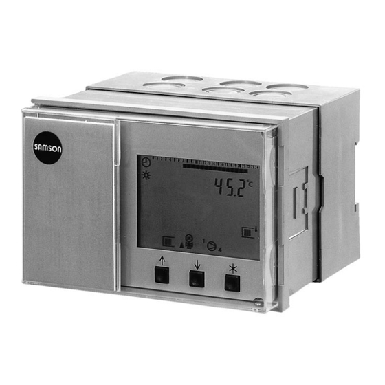
- Page 1 Series 5400 District heating controller TROVIS 5430 Figure 1 ⋅ TROVIS 5430 Mounting and operating instructions Edition July 1997 Firmware release 1.12 EB 5430 EN...
-
Page 2: Table Of Contents
Contents ........Page General ........4 Notes for the user . - Page 3 Operation ....... . . Operating mode selection ......The operating levels .
-
Page 4: General
1. General The digital heating and district heating controller TROVIS 5430 is for weather-sensitive flow temperature control of heating systems, i.e. by way of a heating characteristic the flow tempera- ture of a heating loop is regulated in such a way that the desired room temperature is adjusted, independent of the outside temperature. -
Page 5: Technical Data
1.2 Technical data According to selected system codes, Inputs 2-phase circuit Sensor inputs Maximum of 7 configurable inputs for sensors (PTC or Pt 1000) (Heating/drinking water loop) 2 flow temperature sensors 1 room temperature sensor 1 outdoor temperature sensor 1 return flow temperature sensor 2 storage temperature sensors Binary inputs Storage thermostat... -
Page 6: Resistance Values Of Sensors
1.3 Resistance values of sensors Resistance thermometer with PTC measuring element Sensor resistance elements (with controller disconnected) Sensor for outdoor temperature type 5224, for flow and return flow temperature type 5264, 5265, for storage tank temperature type 5264 °C –20 –10 +90 +100 +110 +120 Ω... -
Page 7: Installation
2. Installation 2.1 Installing the controller The controller consists of the controller housing with electronics and a housing rear panel with terminal strips. The housing rear panel can be ordered as a flat or deep version. To connect electrically, the front screws must be loosened and the controller housing must be se- parated from the rear panel. -
Page 8: Installing The Sensors
Radio interference suppression: The controller type 5430 with SAMSON actuators is interfe- rence-suppressed according to EN 50081 part 1 and 50082 part 1 If other actuators are used,... -
Page 9: Connecting The Actuator
3.4 Connecting the actuator Wire cables as humid area cables with a minimum cross-section of 1.5 mm to the terminals of the controller output. When commissioning, it is necessary to check the direction of rotation, i.e. whether connections have been made correctly by positioning the operating switch to + and - for opening and closing the valve. - Page 10 SF 2 SF 1 RüF GNDF – 12 11 GNDF Option Figure 4 Type 3 1 2 5244 System code number 2 SF 2 SF 1 VF 2 RüF GNDF – 12 11 GNDF Option Figure 5 3 1 2 Type System code number 3 5244...
-
Page 11: Description Of Controller Functions
4. Description of controller functions The following function descriptions are intended to assist comprehension of the settings required for operation. The controller functions depend on the selected system code number, 1, 2, 3, or 4, depicted and described in chapter 5. The tables on pages 37 and 38 can be used to clarify the configuration levels (CO) and function blocks (FB) described in the function descriptions. -
Page 12: Flash Adaptation
4.2 Flash adaptation It is possible to achieve a direct reaction to deviations in room temperature via the function block setting CO1 FB 3 = EIN (linked to FB 1 = ON): so-called flash adaptation counteracts deviations in room temperature within time-controlled rated operation by raising or lowering the heating characteristic by up to 10 °C (parallel adjustment of the heating characteristic). -
Page 13: Delayed Outdoor Temperature Adaptation
mertime operation commences on the second day. If the daytime mean temperature level falls below the outdoor temperature limit on two successive days, then summertime operation is ter- minated on the following day. 4.5 Delayed outdoor temperature adaptation A calculated outdoor temperature is used to determine the flow temperature. This delayed adap- tation occurs a) only if the outdoor temperature falls, or b) independent of outdoor temperature variations. -
Page 14: Thermal Disinfection Of Drinking Water Storage Tank
4.8 Thermal disinfection of drinking water storage tank This function cannot be used in conjunction with a storage tank thermostat. On all systems with heating up of drinking water the function block setting CO2 FB 5 = ON cau- ses the storage tank to be charged at 75 °C every week on a selected day at 0000 hrs. The heat exchanger charging pump TLP is immediately switched on, regardless of the flow tem- perature values which have been measured. -
Page 15: Buildup Of Charging Temperature Via The Return Flow Sensor With
4.10 Buildup of charging temperature via the return flow sensor with the heating loop switched off This function is only active with system code number 2. If, during the usage period, the heating loop is switched off, then in the case of storage tank charging the storage loading pump is only switched on when the temperature at the return flow sensor attains the temperature level measu- red at storage tank sensor 1. -
Page 16: Sensor Failure/Operation Errors
4.15 Sensor failure/operation errors Interruptions or a short circuit of the sensor lines as well as other operational errors are display- ed in the operating level by an ”ERROR” message. If this level is opened, then the controller indi- cates the defective sensors by corresponding combinations of symbols. Operational errors are displayed using the following number codes: Err 1: New reading in of cold start values. -
Page 17: Monitoring Of A Flow Maximum Temperature For Heating Up Of Drinking Water
4.18 Monitoring of a flow maximum temperature for heating up of drinking water If heating up of drinking water with master switchover is selected (possible only on system code number 3), the controller monitors the flow temperature at the flow sensor for the heat exchanger during storage charging. -
Page 18: System Diagrams
5. System diagrams Preliminary remarks: The system diagrams depicted contain only the system components relevant to the control, not however safety relevant system components. If a temperature regulator (TR) or a safety temperature monitor (STW) or additionally a pressure limiter (DB) is required, a control device with a safety function according to DIN 32730 must be used. -
Page 19: System Code Number 2
5.2 System code number 2 Figure 8 ⋅ Anl 2 (System 2) Weather-sensitive flow temperature regulator with variable re- turn flow temperature limiting and heating up of drinking water in the storage tank system Processing heating up of drinking water Four different cases are distinguished: A) The temperature at the flow sensor is higher than the charging temperature setpoint value If the temperature in the storage tank falls below the value for drinking water requirement ON at... - Page 20 B) The temperature at the flow sensor is less than the charging temperature setpoint value, but higher than 40 °C If the temperature in the storage tank falls below the value for drinking water requirement ON at sensor SF1 or if the temperature falls below the value set at the storage tank thermostat, com- mencement of storage tank charging initially only leads to a buildup of the charging temperatu- re via the heating loop.
- Page 21 System code number 2 with CO2 FB 6 = ON selection: 1 (parallel pump operation) Processing heating up of drinking water in the storage tank system with parallel pump operation A) The temperature at the flow sensor is higher than the charging temperature setpoint value If the temperature in the storage tank falls below the value for drinking water requirement ON at sensor SF1 or if the temperature falls below the value set at the storage tank thermostat, com- mencement of storage tank charging initially only leads to a reduction of the excessive flow tem-...
- Page 22 D) Summertime operation or switched off operation A drinking water requirement leads to an immediate buildup of the charging temperature via the storage tank, i.e. the SLP is switched on. The ZP runs according to the function block setting. If CO2 FB 8 = ON, then the SLP is only switched on when the temperature at sensor RüF is higher than the temperature at sensor SF1.
- Page 23 At 5K above the charging setpoint value (measured at flow sensor VF), at the latest after three minutes, the changeover valve begins to conduct the heating medium in the direction of the storage tank. The UP must continue to run for storage tank charging! The ZP runs according to the function block setting.
-
Page 24: System Code Number
5.3 System code number 3 VL RL RüF Zirk. Figure 10 ⋅ Anl 3 (System 3) Weather-sensitive flow temperature regulator with variable return flow temperature limiting and heating up of drinking water in the storage tank char- ging system Processing heating up of drinking water A) The temperature at the flow sensor is higher than the charging temperature setpoint value If the temperature in the storage tank falls below the value for drinking water requirement OFF at sensor SF2 or if the temperature falls below the value set at the storage tank thermostat, com-... - Page 25 tains the temperature at storage tank sensor ON SF1, the SLP is switched on. If the requirement is terminated by exceeding the adjustable differential gap at sensor SF1 or the preset differential gap at the storage tank thermostat, the controller operates again according to the heating char- acteristic;...
- Page 26 B) The temperature at the flow sensor is less than the charging temperature setpoint value, but higher than 40 °C If in the storage tank the temperature falls below the value for warm water requirement ON at sensor SF1 or if the temperature falls below the value set at the storage tank thermostat, com- mencement of storage tank charging initially only leads to a buildup of the charging temperatu- re via the heat exchanger loop parallel to operation of the heating loop;...
-
Page 27: System Code Number 4
5.4 System code number 4 VL RL RüF1 Zirk. Figure 11 ⋅ Anl 4 (System 4) Weather-sensitive flow temperature regulator with variable return flow temperature limiting and heating up of drinking water from the primary loop, as a storage tank heater version Heating up of drinking water with reverse control (with CO2 FB 9 = ON) In case of house stations using a temperature regulator without auxiliary power for heating up of drinking water built into the primary side, priority can be guaranteed for this regulator via rever-... -
Page 29: Operation
6. Operation 6.1 Operating mode selection The operating mode can be selected with the operating switch. The switch is accessible when the door at the front is opened. The default setting is time-controlled operation, the switch positions with their respectively assi- gned symbols are as follows: Time-controlled operation Rated operation... -
Page 30: The Operating Levels
6.2 The operating levels Controller adjustment and operation is via three keys. They enable you to switch from one ope- rating level to another to request data on the display or to enter data. Entry keys: For adjusting and requesting displays and values in ascending and descending or- Accept key: Operating level: for displaying setpoint values entered Parameter level: for selecting and accepting values and data which have been ente-... - Page 31 Date 10:00 Temperatures INFO 1 INFO Error heating loop Operating level with displays Pumps Temperatures INFO 2 manual level drinking water COPA INFO System Parameter data Anl . PA 1 code heating loop number COPA Configuration and parameter level Configuration Parameter data PA 2 CO-SYS...
- Page 32 In the case of an operation error, e.g. a sensor failure, the assigned symbol blinks in the bottom lefthand corner and the menu field Err appears. After entering this level the error is displayed, see chapter 4.15. After connecting the power supply, the basic display with all symbols, the device type 5430, the firmware release, e.g.
- Page 33 Symbol and display value Meaning Remark Hold key down °C Outdoor temperature delayed outdoor temperature when CO1 FB 05 = ON Setpoint value display: Flow temperature °C Hold key down heating (blinks for return flow limiting) Setpoint value display: °C Charging system 2 Hold...
- Page 34 Symbol and display value Meaning Remark On system 2 and 3 with two °C Storage tank storage tank sensors temperature top Display value followed by drinking water requirement ON: Hold key down Display value Storage tank °C drinking water requirement OFF: temperature Hold key down...
-
Page 35: Commissioning And Adjusting The Controller
7. Commissioning and adjusting the controller To commission, switch on the power supply. After brief intermediate displays, the controller switches to the operating level with the time dis- play. To adjust the controller, it must first be configured. The desired user data must then be entered under parameter entries in chapter 7.2. -
Page 36: Code Number Setting
Press and adjust the number of the function block in which an alteration is to be made. Press the function block number blinks. Press to switch the function block on F 01x -1 or Press to switch the function block off F0x - 0 Press the setting is accepted, the next function block appears Carry out adjustment of other function blocks in the same way. -
Page 37: Function Block Lists
7.1.3 Function block lists Function block list for the heating loop (CO1) FB – Function block SZ – Code number required WE – FB set by manufacturer Anl – System code number FB Function Remark (values in parentheses are default values) Room sensor (RF) OFF 1,2,3,4 ON: selection 1 = room control device type 5244... - Page 38 Dur. storage tank char- ON: depending on time program ging circul. pump runs acc. to time program Thermal ON: Only when CO2 FB1=ON Disinfection parameter: 0...7 (3) day of disinfection (0 = daily) Parallel pump Selection only for system 2: operation 1 = parallel pump operation with UP + SLP 2 = trigger changeover valve and UP...
-
Page 39: Sensor Calibration
Sensor calibration OFF 1,2,3,4 Parameter: temperature value (measured value ±10 K) for all sensors connected according to current configuration Default values OFF 1,2,3,4 Brief activation of ON position parameter for reset to default values 7.1.4 Sensor calibration The measured values for all connected sensors can be changed or reset. When calibrating a sensor the currently displayed sensor value is to be altered in such a way that it coincides with a temperature value (comparison value) measured directly at the measu- ring location. -
Page 40: Parameter Entries
7.2 Parameter entries Depending on the configuration which has now been set up, only system specific parameter items are displayed on the parameter level. If you are still on the configuration and parameter level COPA , press the key until PA1 appe- ars in the top right corner of the display to access the parameter item for entry of heating loop data. -
Page 41: Entry Or Modification Of User Data - Overview
7.2.2 Entry or modification of user data - overview Parameter items, screen symbols, default values, remarks Press COPA appears in the display Parameter level PA1 Press to access the COPA level, PA1 appears in the display Press to access the parameter level PA1, the first parameter item for the heating characteristic appears. - Page 42 Heating characteristic level Parallel adjustment of the heating characteristic, upwards (positive value) or downwards (negative value) (–30...+30°C). If a modification is desired: Press the parameter blinks Press and enter the desired adjustment value in °C Press the value is accepted Characteristics according to 4 points (CO1 FB 4 = ON) Press to access parameter level PA1, the menu for the characteristic appears...
- Page 43 Max. flow temperature (min. flow temperature up to 130 °C) Min. flow temperature (20 °C up to max. flow temperature) If max. flow temp. = min. flow temp. is set, this results in fixed value control. Reduction of flow temperature in reduction operation Description, see (0 to 50 °C) Reduced operation, chapter 4.4...
-
Page 44: Heating Utilization Periods
Limiting value of outdoor temperature for summer operation (0 to 50 °C) Room setpoint value Only with optimizing, when Reduced room setpoint value settings CO1 F 02 = 1 and for (10 to 40 °C) flash adaptation F 03 = 1. Optimizing mode 2, 3 Description, optimizing... - Page 45 For rated operation, periods must be entered alternatively between START and STOP. If the 2nd and 3rd time periods are not required, 00:00 should be entered at START and STOP respectively (default setting). If START and STOP are set to the same time value, this results in continuous reduction or standby operation (non-usage).
- Page 46 Pump lag time (60 to 600 secs) Press the symbol blinks Press to alter lag time Press and accept the value entered End appears in the display, heating loop data entry in the parameter level PA1 is complete Press PA2 appears in the display, the parameter level for entry of data for heating up of drinking water Parameter level PA2 entries Drinking water requirement ON...
-
Page 47: Time Data, Heating Up Drinking Water
Charging temperature (return flow setpoint value during heating up of drinking water) On system 2, on system 3, 4 without "storage tank" symbol (20 to 90 °C) Stop charging Max. value for switching off the storage loading pump on system 2 or TLP on system 3) (20 to 90 °C) Max. -
Page 48: Adjustment Of Current Time, Date And Year
Entering current time, date, year as well as public holidays and vacations After pressing the accept key, from the PA2 level directly to the PA-SYS level or from the COPA le- Press until PA-SYS appears Entries in parameter level PA-SYS Press a time value is displayed Press... -
Page 49: Vacations
Vacations (max. of 10 periods may be entered) Default: – – – – Entering vacation periods: Deleting vacation periods: Press start – – – – is displayed Press start of 1st vacation period is displayed Press vacation symbol blinks Press until start of vacation period Press and enter start of vacation... -
Page 50: Data Sheets
8. Data sheets Station User Responsible SAMSON office System code number Function block settings in the configuration levels CO SYS... - Page 51 Heating loop Characteristics and limiting values Return flow characteristic according to gradient Flow charac. acc. to gradient (0.4 to 3.2) [1.8] Level (–30.0 to 30.0) [0.0] °C Reduction red. oper. (0.0 to 50.0) [20.0] °C Return flow characteristic according to gradient RL charac.
- Page 52 Limiting value (2.0 to 10.0) [2.0] °C Control parameter Kp (0.1 to 50.0) [2.0] Tn (1 to 999) [120] s Valve running period Ty (15 to 240) [120] s Diff. gap 2-point outp. (1.0 to 50.0) [5.0] °C Lag time UP (60 to 600) [240] s Usage times heating loop (0700 to 2200 hrs) Start 1 End 1...
- Page 53 Heating up of drinking water Setpoint values Requirement ON (20 to 90) [40] °C Requirement OFF (20 to 90) [45] °C Differential gap (0 to 30) [5] °C (only when CO2 FB 2 = OFF) Charging/setpoint temperature (20 to 90) [55] °C TLP OFF (20 to 90) [48] °C SLP OFF (20 to 90) [48] °C (only when CO2 FB 3 = ON)
- Page 54 End 2 Start 3 End 3...
- Page 55 Code number 1732...
- Page 56 SAMSON AG ⋅ MESS- UND REGELTECHNIK Weismüllerstraße 3 ⋅ D-60314 Frankfurt am Main Postfach 10 19 01 ⋅ D-60019 Frankfurt am Main EB 5430 EN Telephone (0 69) 4 00 90 ⋅ Telefax (0 69) 4 00 95 07...
Need help?
Do you have a question about the TROVIS 5400 Series and is the answer not in the manual?
Questions and answers