
Related Manuals for Samson TROVIS 6495-2


Summary of Contents for Samson TROVIS 6495-2
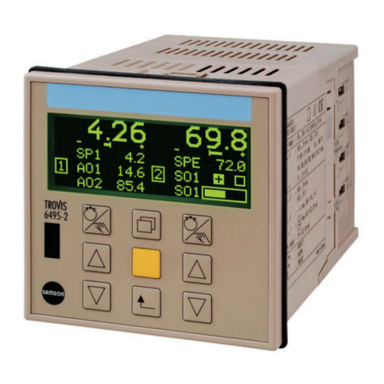
- Page 1 EB 6495-2 EN Translation of original instructions TROVIS 6495-2 Industrial Controller Firmware version 1.11 to 1.21 Edition September 2022...
- Page 2 Note on these mounting and operating instructions These mounting and operating instructions assist you in mounting and operating the device safely. The instructions are binding for handling SAMSON devices. The images shown in these instructions are for illustration purposes only. The actual product may vary.
-
Page 3: Table Of Contents
Contents Safety instructions and measures ..............1-1 Notes on possible severe personal injury ............1-3 Notes on possible property damage .............1-4 Markings on the device ................2-1 Housing inscription ..................2-1 Article code ....................2-2 Firmware versions ..................2-2 Design and principle of operation ...............3-1 Block diagrams ...................3-4 Technical data ..................3-12 Dimensions ....................3-16 Shipment and on-site transport ..............4-1... - Page 4 Memory pen .....................8-21 8.5.3.2 Data transmission between the controller and memory pen......8-22 8.5.4 RS-485/USB interface board ..............8-22 Malfunctions ....................9-1 Troubleshooting ..................9-1 Emergency action ..................9-3 Servicing....................10-1 Decommissioning ..................11-1 Removal ....................12-1 Repairs ....................13-1 13.1 Returning devices to SAMSON ..............13-1 Disposal ....................14-1 EB 6495-2 EN...
- Page 5 Contents Certificates ....................15-1 Annex A (configuration guide) ..............16-1 16.1 Abbreviations ...................16-1 16.2 Configuration list · Functions and parameters ..........16-2 Annex B ....................17-1 17.1 Accessories ....................17-1 17.2 After-sales service ..................17-2 EB 6495-2 EN...
- Page 6 EB 6495-2 EN...
-
Page 7: Safety Instructions And Measures
SAMSON. SAMSON does not assume any liability for damage resulting from the failure to use the de- vice for its intended purpose or for damage caused by external forces or any other external factors. - Page 8 No personal protective equipment is required for the direct handling of the controller. Revisions and other modifications Revisions, conversions or other modifications of the product are not authorized by SAMSON. They are performed at the user's own risk and may lead to safety hazards, for example. Fur- thermore, the product may no longer meet the requirements for its intended use.
-
Page 9: Notes On Possible Severe Personal Injury
Safety instructions and measures Referenced standards, directives and regulations The TROVIS 6495-2 Industrial Controller with a CE marking fulfills the requirements of the Directives 2014/30/EU and 2014/35/EU. The TROVIS 6495-2 Industrial Controller with an EAC marking fulfills the requirements of the Regulations TR CU 004/2011 and TR CU 020/2011. The 'Certificates' section contains this declaration of conformity and TR CU certificate. -
Page 10: Notes On Possible Property Damage
Safety instructions and measures 1.2 Notes on possible property damage NOTICE Risk of damage to the controller due to the supply voltage exceeding the permissible tolerances. The controller is designed for use in low voltage installations. Î Observe the permissible tolerances of the supply voltage. Controller damage caused by water. -
Page 11: Markings On The Device
2 Markings on the device 2.1 Housing inscription The details on the device version are lasered onto the side of the controller housing (see Fig. 2-1). No nameplate is used. SAMSON TROVIS 6495-2 Made in Germany Supply voltage Firmware Analog inputs (AI 1 to 4) -
Page 12: Article Code
Markings on the device 2.2 Article code TROVIS 6495-2 Industrial Controller Supply voltage 85 to 264 V AC 24 V AC/DC 2.3 Firmware versions Firmware revisions 1.11.064 1.11.066 (09-2009) O.1.6 'Constant output value 1 with DI' now also functions in combination with C.4.1-6 'Operation mode after restart, Manual, start AO = AO.K1'. In firmware version 1.11.066, the use of 1.C.2.2.3-1 to 1.C.2.2.3-4 'Open cascade with DI' results in a memory error. - Page 13 Markings on the device Firmware revisions 1.11.070 Section C.3.1.3 Error signal: − E.TZ Operating threshold [0.00 to 110.00 %], firmware version 1.11 and lower [0.0 to 110.0 %] Section C.3.2.9 Arithmetic operation output YPID: − In firmware version 1.21 and higher, the disturbance variable B is linked to YPID over C.3.2.9 as an unscaled value.
- Page 14 Markings on the device Firmware revisions 1.11.070 Section D.1.1 Communication monitoring: − An entry is made in the error list and event list in the event of timeout in firmware version 1.21 and higher. The fault indication icon is also indicated in the display. −...
-
Page 15: Design And Principle Of Operation
TROVIS-VIEW provides a uniform user nent control) interface that allows users to configure and − Operation with up to four internal set parameterize various SAMSON devices points and one external set point, either using device-specific database modules. The analog or via interface (SPC mode) device module for TROVIS 6495-2 can be... - Page 16 Design and principle of operation Inputs − Invert digital input − 4 analog inputs (AI1 to AI4) − Switchover between internal set points DIP switches at the side of the housing to − Switchover to external set point select current or resistance inputs. The −...
- Page 17 Design and principle of operation − 7 digital outputs (4 relay outputs and 3 − RS-232/USB interface board transistor outputs) − One RS-232 interface with RJ-12 The relay outputs can be used as follows: jack − SO1 and SO2 as on/off or three- −...
-
Page 18: Block Diagrams
Design and principle of operation TROVIS 6495-2 mA, V, Pt 100, Pt 1000 mA,V mA, V, Pt 100, Pt 1000, Analog outputs mA,V Analog Potentiometers inputs mA, V, Pt 100, Pt 1000 mA,V Digital outputs mA, V, Pt 100, Pt 1000... - Page 19 Design and principle of operation EB 6495-2 EN...
- Page 20 Design and principle of operation EB 6495-2 EN...
- Page 21 Design and principle of operation EB 6495-2 EN...
- Page 22 Design and principle of operation EB 6495-2 EN...
- Page 23 Design and principle of operation EB 6495-2 EN...
- Page 24 Design and principle of operation Î 3-10 EB 6495-2 EN...
- Page 25 Design and principle of operation EB 6495-2 EN 3-11...
-
Page 26: Technical Data
Design and principle of operation 3.2 Technical data Table 3-1: Technical data · TROVIS 6495-2 Inputs mA, V, Pt 100, Pt 1000, input 2 also for resistance 4 analog inputs transmitter (potentiometer) Version Differential input Nominal signal range 0 to 20 mA, 4 to 20 mA, 0 to 10 V, 2 to 10 V Resolution <0.007 %, relating to nominal signal range Current or... - Page 27 300 V AC, in parallel to each relay contact 3 electrically isolated transistor outputs Transistor outputs External supply 3 to 42 V DC, max. 30 mA Interfaces Transmission protocol SAMSON-specific protocol (SSP) Data that can be trans- Controller settings, process variables, operating mitted status Infrared Transmission rate 9600 bit/s...
- Page 28 Design and principle of operation RS-232 with electrical insulation, USB (slave) USB: 5-pin mini-B Connection RS-232: RJ-12 RS-232/USB USB: SAMSON-specific protocol (SSP) (accessories) Transmission protocol RS-232: SSP and Modbus RTU Data that can be trans- Controller settings, process variables, operating...
- Page 29 Design and principle of operation IP 65 (front), IP 30 (housing), IP 00 (terminals) Degree of protection according to EN 60529 According to EN 61010-1: Protection class II, Device safety overvoltage category II, degree of contamination 2 Requirements according to EN 61000-6-2, Electromagnetic compatibility EN 61000-6-3 and EN 61326-1 Sinusoidal vibration according to IEC 60068-2-6: 2 to 9 Hz;...
-
Page 30: Dimensions
Design and principle of operation 3.3 Dimensions 150 (5.90") 96 (3.78") 156 (6.14") Fig. 3-2: Dimensions in mm (inch) 3-16 EB 6495-2 EN... -
Page 31: Shipment And On-Site Transport
(Important Product Information) 2. Check the shipment for transportation Fig. 4-1: Scope of delivery damage. Report any damage to SAMSON and the forwarding agent (re- 4.3 Transporting the industrial fer to delivery note). controller 4.2 Removing the packaging Transport instructions from the industrial con- −... -
Page 32: Storing The Industrial Controller
Risk of controller damage due to improper storage. Î Observe the storage instructions. Î Avoid long storage times. Î Contact SAMSON in case of different storage conditions. Note We recommend regularly checking the in- dustrial controller and the prevailing storage conditions during long storage periods. -
Page 33: Installation
Installation 5 Installation 5.3 Mounting the industrial controller The work described in this section is only to be performed by personnel appropriately The TROVIS 6495-2 Industrial Controller is qualified to carry out such tasks. designed for panel mounting (see Fig. 5-2 and the 'Design and principle of operation' 5.1 Installation conditions section). -
Page 34: Installing The Interface Board
Installation Immersion depth with terminals (without wiring): 151 (5.95") +0,8 +0,3 (3.62" Mounting clamp Seal >15 Panel cut-out on install- ing several controllers Fig. 5-2: Installation · Dimensions in mm (inch) 5.4 Installing the interface 1. Switch off the supply voltage. board 2. -
Page 35: Electrical Connection
Installation rails intended for it and that the cover Notes on electric wiring engages. Î Install the power supply lines and the sig- nal lines separately. Do not install them parallel to each other. Î To improve noise immunity, observe a minimum distance of 10 cm between the power line and the measuring input line. - Page 36 Installation Potentiometers The analog input AI2 is designed for the connection of a potentiometer with two-wire or three-wire connection. Potentiometers be- tween 50 and 1200 Ω can be connected. A potentiometer is used, for example for po- sition feedback of an electrical actuator or for input of an external set point.
- Page 37 Installation Terminal Current Current Voltage Resistance Potentiometers Two-wire thermometer block 1 transmitter 0/4 ... 20 mA 4 ... 20 mA 0/2 ... 10 V Pt 100/Pt 1000 100/200/500/1000 Three-wire Two-wire Three-wire Two-wire DIP switches Supply – output 1) – – Input AI1 –...
- Page 38 Installation Terminal block 2 Current Voltage Digital input powered Digital input externally by the controller powered 0/4...20 mA 0/2...10 V Supply output 21 V DC – max. 90 mA Analog output AO1 – – Digital input DI1 24 V DC – – Digital input DI2 Analog output AO2 –...
- Page 39 Installation Terminal block 3 Power supply 3 to 42 V DC, max. 30 mA – Digital output DO5 – Digital output DO6 – Digital output DO7 Terminal block 4 L (+) Supply voltage 85...264 V AC 24 V AC/DC (20...30 V) N (–) Terminal block 5 Three-step output for On/off output with...
- Page 40 Installation Galvanic isolation Analog inputs Analog outputs Digital outputs (relay) Digital inputs for three-step, on/off, limit alarms Internal supply Digital outputs (transistor) Digital inputs for fault and status alarms External supply Interface Transmitter supply Electrical isolation Supply voltage Fig. 5-8: Galvanic isolation EB 6495-2 EN...
-
Page 41: Operation
Operation 6 Operation 6.1 Device overview Display Key panel with operator keys Infrared interface DIP switches (at the side of the housing) DIP switches Fig. 6-1: Display and operating controls (the controller is in the operating level) EB 6495-2 EN... - Page 42 Operation Infrared adapter COM port (RS-232, D-sub 9-pin) for computer or USB to RS-232 adapter Fixture for infrared adapter USB to RS232 adapter Fig. 6-2: Connecting the infrared interface EB 6495-2 EN...
-
Page 43: Operating Controls
Operation 6.2 Operating controls Key panel with operator keys − Left and right row: Display Manual/automatic key While in operation, the controller is in the Cursor key (up) operating level. Cursor key (down) The display is divided into two sections. Each −... -
Page 44: Operating Structure
Operation 6.3 Operating structure The controller has the following levels: Operating level Î See Fig. 6-1. The controller is in this level while in opera- tion. Key information on the control process is displayed in this level. Info menu Î See the 'Operation' section. Information on the running process and firm- ware version can be viewed in the info menu. - Page 45 Operation Table 6-1: Overview: Function of keys depending on the level Operator Operating level Info menu Operating menu Configuration menu − Switch between − No function − No function − Edit individual manual and items of parameters Manual/ automatic control automatic mode −...
- Page 46 EB 6495-2 EN...
-
Page 47: Start-Up And Configuration
Start-up and configuration 7 Start-up and configuration The work described in this section is only to Settings at the controller can also be be performed by personnel appropriately performed on a computer using the TROVIS- qualified to carry out such tasks. VIEW software: Each menu of the configuration menu has its Before start-up, make sure the following con-... - Page 48 Start-up and configuration 5. Determine the control algorithm, e.g. Two DIP switches are assigned to each ana- log input AI1 to AI4. C.3.1.1. 6. Assign the output, e.g. O.1.1-1. − Both DIP switches on the right: Current signal (mA or V) 7.
- Page 49 Start-up and configuration Digital inputs The following functions that have been defined over the C Controller, O Output and A General settings menus can be assigned to a digital input. Function Menu item Invert digital input I.1.5…I.1.8 Switchover between internal set points C.2.2.1 Switchover to external set point C.2.2.2...
- Page 50 Start-up and configuration Configuration menu ----------------- ---------------------------------- → Operating Operating menu Configuring the controller (see level Contr. [1] section 7.1.2) Configuration M Control mode Setting the control mode This menu contains the I Input configuration of analog inputs AI1 to AI4 and digital inputs DI1 to DI4.
-
Page 51: Entering The Configuration Menu
Start-up and configuration 7.1.1 Entering the 7.1.2 Configuring the configuration menu controller The controller is currently in the operating The controller is configured by setting the level: configuration items and associated parame- ters. Each configuration item has its own code, which gives information on its position in the configuration menu. -
Page 52: Setting Configuration Items
Start-up and configuration Setting configuration items … If the configuration item that you want to set is not in the M Control mode menu, select the menu required: − I Input − C Controller [1]/[2] − O Output − D Communication Note −... -
Page 53: Configuration Example
Start-up and configuration Return to the operating level Note … Return to the operating level stepwise. The analog input AI1 can only be configured as a Pt 1000 input when the DIP switches are positioned for “Pt 100/Pt 1000“. Both DIP switches AI1 (at the side of the controller housing) must set to the position “Pt 100/Pt 1000“... -
Page 54: Adapting The Display Direction
Start-up and configuration 1x Enter I.1 Analog input AI1 sub- 1x Select AI1.MAX Upper range val- menu. ue parameter. The I.1.1 Input signal configuration 1x Activate AI1.MAX Upper range item is displayed together with its cur- value parameter. rent setting: I.1.1-6 = Pt 100. The upper range value setting is high- lighted: 100.0 °C 1x Activate the I.1.1 Input signal con-... -
Page 55: Changing The Controller Display
Start-up and configuration − Switching Controller [1] and Controller The controller is currently in the operating [2] displays level: Î See section 7.1.3.3. 7.1.3.1 Changing the controller display The controller display is adapted in the C.5 Î Enter the configuration menu (see sec- Controller display submenu of the corre- tion 7.1.1). - Page 56 Start-up and configuration The 1C.5.1 Row 1 configuration item The currently active setting is displayed: is displayed together with the current 1C.5.7-1 = Numerical setting: 1C.5.1-1 = Actual value PV0 1x Activate 1C.5.7 configuration item. at comparator The currently active setting is highlight- 5x Select 1C.5.6 Row 5 configuration ed: Numerical.
-
Page 57: Setting Up Additional Display
Start-up and configuration 7.1.3.2 Setting up additional Example: Based on the example in sec- tion 7.1.3.1, an additional display is to be display set up If rows 1 to 5 in the display are all assigned for Controller [1] in the right display section. and further variables are to be displayed, an Its fourth row is to display the output AO2 additional display can be added. - Page 58 Start-up and configuration Set up additional display 2x Exit O Output menu. 1x Select 1C Controller [1] menu. The O.1 Analog output AO1 sub- menu is highlighted. 1x Select O.2 Analog output AO2 sub- menu. 1x Activate 1C Controller [1] menu. 1x Enter O.2 Analog output AO2 sub- The 1C.1 Input variables submenu menu.
- Page 59 Start-up and configuration The currently active setting is displayed: 1x Confirm setting. 1C.6.7-0 = Off Activate additional display 1x Activate 1C.6.7 Row 4 configuration item. 2x Return to menu list. The currently active setting is highlight- ed: Off. 3x Change setting to C.6.7-3 (Output AO2).
- Page 60 Start-up and configuration 1x Confirm setting. 1x Enter A.2 Operation display sub- menu. The A.2.1 Left display configuration item is displayed together with its cur- rent setting: A.2.1-1 = Controller [1] 1x Select A.2.2 Right display submenu. The currently active setting is displayed: Right display = Off.
-
Page 61: Switching Controller [1] And Controller [2] Displays
Start-up and configuration Return to the operating level Note 4x Return to the operating level. Before Controller [1] can be assigned to the right display, it must first be removed from the left display as one controller cannot be assigned to both displays at the same time. The controller is currently in the operating In the additional reading on the right level:... - Page 62 Start-up and configuration Configure right display 1x Select A.2 Operation display sub- menu. 1x Select A.2.2 Right display configu- ration item. 1x Enter A.2 Operation display sub- menu. 1x Activate A.2.2 Right display config- uration item. The currently active setting is highlight- ed: Controller [2] 2x Change setting to A.2.2-1 (Controller [1]).
-
Page 63: Configuration Using The Trovis-View Software
TROVIS-VIEW provides a uniform user AI1 and Pt100 (see Annex A). interface that allows users to configure and parameterize various SAMSON devices 2. Set the signal source to the initial value. using device-specific database modules. The If the input value is within the range that TROVIS 6495-2 device module can be... -
Page 64: Calibrating Analog Outputs
Start-up and configuration End value End value 1. Activate End menu item depending on 1. Activate End menu item depending on the analog input and signal type. the analog output and signal type. Example: A.20.1.10 for Analog input Example: A.20.5.2 for Analog output AI1 and Pt 100 (see Annex A). -
Page 65: Operation
Operation 8 Operation Default reading on display: Row 1 Actual value PV0 at 8.1 Operating level comparator Row 2 Error signal +/–e While in operation, the controller is in the Row 3 Set point SP1 ... SP4, SPE, SPC operating level. Key information on the con- Row 4 Output according to priority trol process is displayed in this level. -
Page 66: Adjusting The Set Point
Operation 8.1.1 Adjusting the set point The display in the operating level is ar- ranged depending on the control mode se- Change the set point in automatic mode us- lected. For control modes with two control- ing the cursor keys: lers, the default display has two sections: Controller [1] on the left display section and Increase the set point. -
Page 67: Opening/Closing Cascade
Operation The hand icon appears above the Note controller designation [1]/[2]. In the following example, the master control- The currently active manipulated vari- ler [2] is shown on the right display (default). able (output) is highlighted: AO1 = As a result, the manual/automatic key on the 46.5 % right is used to open/close the cascade. -
Page 68: Info Menu
Operation 8.2 Info menu Enter info menu 1x Change to the info menu. Information on the running process and the controller can be viewed in the info menu. Usually, there are the following menu items Controller [1], possibly Controller [2], Inputs/outputs, Last events, Diagno- sis and Versions. - Page 69 Operation Info menu ---------------- ---------------- Operating level Info menu Contr. [1] Set point Input variable PV, … 2) Output If an error message exists, the Contr. [2] See Controller [1] corresponding menu item is added to the info menu. The Error message submenu Inputs/ Analog inputs AI1…4...
- Page 70 Operation Notes concerning the readings in the info menu − Inputs/outputs menu item Directly after the digital inputs and outputs, the state of the input/output is indicated: (0) or (1) In the case of a reversed digital input or output, the state of the input/output in reversed form is additionally indicated: inv.(1) or inv.(0) The controller assigned to the input/output is indicated on the right of the display ([1] or [2])
- Page 71 Operation − Diagnosis - 1 menu item Operating time indicates the time the controller has been operating since the last start-up of the controller in days.hours:Minutes:Seconds. The total operating time refers to how long the controller has been supplied with voltage (Days. Hours:Minutes:Seconds).
-
Page 72: Operating Menu
Operation 8.3 Operating menu The operating menu consists of the Control parameters and Set point menu items. The following actions can be performed: − Changing control parameters Operating menu Contr. [1] is Î See section 8.3.2. highlighted. − Switching over internal/external set point 1x Enter Operating menu Contr. - Page 73 Operation Operating menu ---------------- ---------------- ------------------------------ € Operating Operating Control KP (prop.-action coefficient) level menu Contr. [1] parameters Change the control TN (reset time) Operating parameters (see menu Contr. [2] section 8.3.2) TV (derivative-action time) Y0 (operating point) TV.K (der.-action gain TV.K1) 1.P+ (PWM duty cycle SO1.P+) 1.P–...
-
Page 74: Changing The Control Parameters
Operation 8.3.2 Changing the control Change the reset time TN parameters 1x Activate Control parameters menu item. After entering the operating menu (see sec- tion 8.3.1), the control parameters are changed in the Control parameters menu item. Depending on the control behavior, the proportional-action coefficient KP, reset time TN, derivative-action time TV, derivative-ac- The actual value at the comparator... -
Page 75: Switching Over Internal/External Set Point
Operation Î Enter the operating menu (see sec- The current value of the reset time is tion 8.3.1). highlighted: 120 s. Switchover to the internal set point SPI … Keep pressed and change the reset time TN to 100 s. 1x Select Set point menu item. 1x Confirm the reset time. -
Page 76: Switching Over And Changing Internal Set Points
Operation − The set point SP1 is to be switched over to set point SP2. Note Determining and changing the internal set − The set point SP1 is to be kept at 70 point is described in section 8.3.4. while the set point SP2 is to be changed to 100. - Page 77 Operation The actual value at the comparator The set point SP1 has the required val- PV0 ( ), the set point at the compara- ue of 70.0 and therefore does not need tor SP0 ( ) and the manipulated vari- to be changed.
-
Page 78: Locking The Controller
Operation 8.4.1 Locking the operating with holding register 55 (Controller [1]) and 115 (Controller [2]) u KH 6495-2. level − Value 1 = Set point SP1 active − Value 2 = Set point SP2 active Switchover between manual and automatic − Value 3 = Set point SP3 active mode as well as changes to the set point for −... -
Page 79: Locking All Keys Over A Digital Input
Operation Activate locking 2x Select 1C Controller [1] menu. 1x Confirm setting. 4x Return to the operating level. 1x Activate 1C Controller [1] menu. Set point adjustment is locked in auto- The 1C.1 Input variables submenu matic mode in the operating level. is highlighted. -
Page 80: Activating Key Number Operation
Operation 1x Enter A General settings menu. 1x Confirm setting. 4x Return to the operating level. The operator keys are locked when the digital input DI2 is active. Settings cannot be changed. The A.1 Language / Sprache 8.4.3 Activating key number submenu is highlighted. - Page 81 Operation The controller is currently in the operating The A.4.1 Key number operation level. configuration item is displayed togeth- Î Enter the configuration menu (see the er with the currently active setting: 'Start-up and configuration' section). A.4.1-0 = Off Activating key number operation 1x Activate A.4.1 Key number opera- tion configuration item.
-
Page 82: Data Transmission
From now on, changes to control pa- interface that allows users to configure and rameter settings in the operating menu parameterize various SAMSON devices and changes in the configuration menu using device-specific database modules. The can only be performed after the key TROVIS 6495-2 device module can be... -
Page 83: Infrared Interface
RJ-12 jack cessed from the front of the controller. It is lo- or over the USB port. In addition, a memory cated above the SAMSON logo (see pen (see Annex B) can be inserted into the Fig. 6-1). - Page 84 Operation The RS-232/USB interface board includes transmission between the RS-232 interface one of the following interfaces: and the COM port of the computer. − RS-232 interface (RJ-12 jack) A connecting cable RJ-12/D-sub 9 pin and the USB to RS-232 adapter (see the 'Opera- −...
-
Page 85: Memory Pen
Operation 8.5.3.1 Memory pen Note The memory pen-64 can only be used when the controller is fitted with a RS-232/USB in- terface board. The memory pen-64 (see Fig. 8-2) serves as a data carrier and is able to load and save data (configuration, parameters) in its non-volatile memory. -
Page 86: Data Transmission Between The Controller And Memory Pen
Operation 8.5.3.2 Data transmission Memory pen >> 6495: Data are down- loaded from the memory pen to the con- between the troller. controller and 3. Confirm setting ( ). memory pen Data transmission starts. 1. Insert the memory pen into the RJ-12 The following display appears when da- jack at the RS-232/USB board of the ta transmission is completed:... - Page 87 Operation A USB cable (see the 'Operation' section) is TROVIS 6495-2 EIA-485 standard Signal used for data transmission between the USB interface and the USB port of the computer. Rx– Tx– A two-pin or four-pin shielded cable is used for data transmission between the RS-485 interface and a RS-485 port of a computer.
- Page 88 Operation TROVIS 6495 1 RJ-12 jack (RS-232/USB interface board) 2 Infrared interface 3 USB port (RS-232/USB and RS-485/USB inter- face boards) 4 USB cable (mini-B, 5-pin USB type A) USB to RS232 adapter 5 Infrared adapter (RS-232) 6 Connecting cable RJ-12/D-sub, 9 pin (RS-232) 7 Memory pen-64, RJ-12 connector (only with RS- 232/USB interface board) 8 Modular adapter RJ-12/D-sub 9 pin (RS-232)
- Page 89 Operation Network structure We recommend not to connect more than three repeaters in series. As a result, Fig. 8-5 shows an example for the setup of lines of 4800 m can be achieved. Ten of an automation system with data exchange such lines can be connected in parallel using Modbus protocol.
- Page 90 8-26 EB 6495-2 EN...
-
Page 91: Malfunctions
Malfunctions 9 Malfunctions DANGER Risk of electric shock while performing electrical connection. For electrical installation, you are required to observe the relevant electrotechnical regula- tions of the country of use as well as the regulations of the local power suppliers. Î... - Page 92 − We recommend for any errors not described in detail to switch off the power supply and to wait approx. five seconds before switching it on again. − Contact SAMSON's After-sales Service for malfunctions not listed in the table. The digital outputs DO5 and DO6 can be configured so that they are activated when a sen- sor/signal error or communication failure occurs.
-
Page 93: Emergency Action
Malfunctions Error Possible reasons Recommended action Internal temperature The permissible ambient tem- Î Check the ambient tempera- Temperature too low perature range between 0 and ture. (–5 °C) 50 °C has not been kept. Î Check location of installa- tion. Internal temperature Temperature too high (65 °C) Communication failure... - Page 94 EB 6495-2 EN...
-
Page 95: Servicing
− The product warranty becomes void if service or repair work not described in these instruc- tions is performed without prior agreement by SAMSON's After-sales Service. − Only use original spare parts by SAMSON, which comply with the original specifications. Table 10-1: Recommended inspection and testing... - Page 96 10-2 EB 6495-2 EN...
-
Page 97: Decommissioning
Decommissioning 11 Decommissioning The work described in this section is only to be performed by personnel appropriately qualified to carry out such tasks. DANGER Risk of electric shock while performing electrical connection. For electrical installation, you are required to observe the relevant electrotechnical regulations of the country of use as well as the regulations of the local power suppliers. - Page 98 11-2 EB 6495-2 EN...
-
Page 99: Removal
Removal 12 Removal The work described in this section is only to be performed by personnel appropriately qualified to carry out such tasks. 1. Pull off terminal strips. 2. Unscrew the threaded rods of the mount- ing clamps using a screwdriver. 3. - Page 100 12-2 EB 6495-2 EN...
-
Page 101: Repairs
Risk of controller damage due to incorrect service or repair work. Î Do not perform any repair work on your own. Î Contact SAMSON's After-sales Service for service and repair work. 13.1 Returning devices to SAMSON Defective industrial controllers can be re- turned to SAMSON for repair. - Page 102 13-2 EB 6495-2 EN...
-
Page 103: Disposal
Disposal 14 Disposal SAMSON is a producer registered at the following European institution u https://www.ewrn.org/ national-registers/national- registers. WEEE reg. no.: DE 62194439/FR 025665 Î Observe local, national and internation- al refuse regulations. Î Do not dispose of components, lubricants and hazardous substances together with your other household waste. - Page 104 14-2 EB 6495-2...
- Page 105 Certificates 15 Certificates The following certificates are included on the next pages: − EU declaration of conformity − TR CU certificate The certificates shown were up to date at the time of publishing. The latest certificates can be found on our website: u www.samsongroup.com >...
- Page 106 LVD 2014/35/EU EN 60730-1:2016, EN 61010-1:2010 RoHS 2011/65/EU EN 50581:2012 Hersteller / Manufacturer / Fabricant: SAMSON AKTIENGESELLSCHAFT Weismüllerstraße 3 D-60314 Frankfurt am Main Deutschland/Germany/Allemagne Frankfurt / Francfort, 2017-07-29 Im Namen des Herstellers/ On behalf of the Manufacturer/ Au nom du fabricant.
- Page 107 Certificates TR CU certificate EB 6495-2 15-3...
- Page 108 Certificates 15-4 EB 6495-2...
- Page 109 Certificates EB 6495-2 15-5...
- Page 110 15-6 EB 6495-2...
- Page 111 Annex A (configuration guide) 16 Annex A (configuration guide) 16.1 Abbreviations Abbreviation Meaning Analogeingang (Analog Input) Analogausgang (Analog Output) Digitaleingang (Digital Input) Digitalausgang (Digital Output) Auxiliary variable, disturbance variable or leading process variable in ratio control Error Position feedback Proportional-action coefficient Process variable Actual value at comparator Process Variable Ratio...
- Page 112 Annex A (configuration guide) 16.2 Configuration list · Functions and parameters Information on the configuration list Some functions and parameters can only be selected after certain initial settings have been made beforehand. The initial settings required are specified in angle brackets in the follow- ing list.
- Page 113 Annex A (configuration guide) Analog input AI1 Default Setting setting I.1.2 Decimal point I.1.2-1 -0 XXXX No decimal place -1 XXX.X 1 decimal place -2 XX.XX 2 decimal places -3 X.XXX 3 decimal places I.1.3 Physical unit I.1.3-1 -0 Off <not with I.1.1-6/-7>...
- Page 114 Annex A (configuration guide) Analog input AI1 Default Setting setting I.1.6 Manual mode Controller [1] upon signal failure <I.1.5≠0> I.1.6-0 -0 Off -1 Constant output value at AO1 <O.1.1-1> -2 Constant output value at AO2 <O.2.1-1> -3 Constant output value at AO3 <O.3.1-1>...
- Page 115 Annex A (configuration guide) Analog input AI2 Default Setting setting I.2.1 Input signal I.2.1-6 -1 4–20 mA <both DIP switches on right: mA/V> -2 0–20 mA <both DIP switches on right: mA/V> -3 0–10 V <both DIP switches on right: mA/V> -4 2–10 V <both DIP switches on right: mA/V>...
- Page 116 Annex A (configuration guide) Analog input AI2 Default Setting setting -16 mmFS Filling level <not with I.2.1-6/-7> -17 inH Filling level (inch water <not with I.2.1-6/-7> column) -18 %rF Relative humidity <not with I.2.1-6/-7> -19 kg/m³ Density <not with I.2.1-6/-7> -20 pH <not with I.2.1-6/-7>...
- Page 117 Annex A (configuration guide) Analog input AI2 Default Setting setting -6 With last output value <O.1.1-2/O.2.1-2/O.3.1-2/ O.4.1-2/O.5.1-2> AO1.K1 Constant output value at AO1 <I.2.7-1> [–10.0 ... 110.0 %] 0.0 % AO2.K1 Constant output value at AO2 <I.2.7-2> [–10.0 ... 110.0 %] 0.0 % AO3.K1 Constant output value at AO3 <I.2.7-3>...
- Page 118 Annex A (configuration guide) Analog input AI3 Default Setting setting -12 t/h Mass flow <not with I.3.1-6/-7> -13 lb/h Mass flow <not with I.3.1-6/-7> -14 % <not with I.3.1-6/-7> -15 mFS Filling level <not with I.3.1-6/-7> -16 mmFS Filling level <not with I.3.1-6/-7>...
- Page 119 Annex A (configuration guide) Analog input AI3 Default Setting setting I.3.7 Manual mode Controller [2] upon signal failure I.3.7-0 <M.1-5/-6, I.3.5≠0> -0 Off -1 Constant output value at AO1 <O.1.1-2> -2 Constant output value at AO2 <O.2.1-2> -3 Constant output value at AO3 <O.3.1-2>...
- Page 120 Annex A (configuration guide) Analog input AI4 Default Setting setting I.4.3 Physical unit I.4.3-0 -0 Off <not with I.4.1-6/-7> -1 °C Temperature -2 °F Temperature -3 K Temperature <not with I.4.1-6/-7> -4 bar Pressure <not with I.4.1-6/-7> -5 mbar Pressure <not with I.4.1-6/-7>...
- Page 121 Annex A (configuration guide) Analog input AI4 Default Setting setting I.4.6 Manual mode Controller [1] upon signal failure <I.4.5≠0> I.4.6-0 -0 Off -1 Constant output value at AO1 <O.1.1-1> -2 Constant output value at AO2 <O.2.1-1> -3 Constant output value at AO3 <O.3.1-1>...
- Page 122 Annex A (configuration guide) Digital input DI2 Default Setting setting I.6.1 Invert I.6.1-0 -0 Off -1 On Digital input DI3 Default Setting setting I.7.1 Invert I.7.1-0 -0 Off -1 On Digital input DI4 Default Setting setting I.8.1 Invert I.8.1-0 -0 Off -1 On C Controller Note...
- Page 123 Annex A (configuration guide) C.1.1 Input variable PV Default Setting Con- setting troller C.1.1.4 Function generation <C.1.1.1≠0> C.1.1.4-0 [1] [2] -0 Off [1] [2] -1 On [1] [2] PV.MIN Lower range value output func- tion generation <C.1.1.4-1> [–999.0 ... 9999.0] [1] [2] PV.MAX Upper range value output func- tion generation <C.1.1.4-1>...
- Page 124 Annex A (configuration guide) C.1.1 Input variable PV Default Setting Con- setting troller [1] [2] -15 mFS Filling level [1] [2] -16 mmFS Filling level [1] [2] -17 inH Filling level (inch water column) [1] [2] -18 %rF Relative humidity [1] [2] -19 kg/m³...
- Page 125 Annex A (configuration guide) C.1.2 Input variable SPE Default Setting Con- setting troller [1] [2] SPE.O5 Output value 5 <C.1.2.4-1> [–999.0 ... 9999.0] [1] [2] SPE.I6 Input value 6 <C.1.2.4-1> [–999.0 ... 9999.0] [1] [2] SPE.O6 Output value 6 <C.1.2.4-1> [–999.0 ...
- Page 126 Annex A (configuration guide) C.1.3 Input variable DV Default Setting Con- setting troller C.1.3.2 Filter <C.1.3.1≠0> C.1.3.2-0 [1] [2] -0 Off [1] [2] -1 On [1] [2] DV.T Time constant <C.1.3.2-1> [0.1 ... 100.0 s] 1.0 s C.1.3.3 Root extraction <C.1.3.1≠0> C.1.3.3-0 [1] [2] -0 Off...
- Page 127 Annex A (configuration guide) C.1.3 Input variable DV Default Setting Con- setting troller [1] [2] -8 m³/h Flow rate [1] [2] -9 l/h Flow rate [1] [2] -10 ft³/h Flow rate [1] [2] -11 kg/h Mass flow [1] [2] -12 t/h Mass flow [1] [2] -13 lb/h...
- Page 128 Annex A (configuration guide) C.1.4 Input variable TR Default Setting Con- setting troller [1] [2] TR.I2 Input value 2 <C.1.4.4-1> [–999.0 ... 9999.0] [1] [2] TR.O2 Output value 2 <C.1.4.4-1> [–999.0 ... 9999.0] [1] [2] TR.I3 Input value 3 <C.1.4.4-1> [–999.0 ...
- Page 129 Annex A (configuration guide) C.1.5 Input variable FB Default Setting Con- setting troller C.1.5.1 Assign source C.1.5.1-0 [1] [2] -0 Off [1] [2] -1 Analog input AI1 [1] [2] -2 Analog input AI2 [1] [2] -3 Analog input AI3 [1] [2] -4 Analog input AI4 C.1.5.2 Filter <C.1.5.1≠0>...
- Page 130 Annex A (configuration guide) C.2.1 Set point adjustment Default Setting Con- setting troller [1] [2] SP3.MAX Upper adjustment limit <C.2.1.1-3/-4> [–999.0 ... 9999.0] 100.0 [1]<M.1-2/-6>: [0.0 ... 9999.0] [1] [2] SP4 Set point <C.2.1.1-4> [–999.0 ... 9999.0] [1]<M.1-2/-6>: [0.0 ... 9999.0] [1] [2] SP4.MIN Lower adjustment limit <C.2.1.1-4>...
- Page 131 Annex A (configuration guide) C.2.1 Set point adjustment Default Setting Con- setting troller C.2.1.5 Physical unit for set points C.2.1.5-1 [1] [2] -0 Off The unit is already set [1] [2] -1 °C Temperature depending [1] [2] -2 °F Temperature on PV.
- Page 132 Annex A (configuration guide) C.2.1 Set point adjustment Default Setting Con- setting troller -5 Constant output value at SO2 <O.1.5-1/-38/-39> -6 With last output value <O.1.1-1/-38/-39/O.2.1-1/-38/-39/O.3.1-1/-38/-39/ O.4.1-1/-38/-39/O.5.1-1/-38/-39> -1 Constant output value at AO1 <O.1.1-2/-38/-39> -2 Constant output value at AO2 <O.1.2-2/-38/-39> -3 Constant output value at AO3 <O.1.3-2/-38/-39>...
- Page 133 Annex A (configuration guide) C.2.2 Set point switchover Default Setting Con- setting troller C.2.2.2 Changeover to external set point with DI C.2.2.2-0 <C.2.1.2≠0>; M.1-3: Controller [2] only [1] [2] -0 Off [1] [2] -1 With digital input DI1 [1] [2] -2 With digital input DI2 [1] [2] -3 With digital input DI3...
- Page 134 Annex A (configuration guide) C.2.3 Set point ramp function Default Setting Con- setting troller C.2.3.1 Set point ramp C.2.3.1-0 [1] [2] -0 Off [1] [2] -1 Start with DI1, SP=PV [1] [2] -2 Start with DI2, SP=PV [1] [2] -3 Start with DI3, SP=PV [1] [2] -4 Start with DI4, SP=PV [1] [2]...
- Page 135 Annex A (configuration guide) C.2.4 Additional set point functions Default Setting Con- setting troller C.2.4.2 Linking up external/internal set point C.2.4.2-0 <C.2.1.2≠0> [1] [2] -0 Off [1] [2] -1 Min. selection (SPI, SPE) [1] [2] -2 Max. selection (SPI, SPE) [1] [2] -3 SPI + SPE [1] [2]...
- Page 136 Annex A (configuration guide) C.3.1 Control response Default Setting Con- setting troller [1] [2] KP Proportional-action coefficient [0.01 ... 100.0] 1.00 [1] [2] TN Reset time <C.3.1.1-1/-4/-5> [1 ... 9999 s] 120 s [1] [2] TV Derivative-action time [1 ... 9999 s] 10 s <C.3.1.1-3/-4>...
- Page 137 Annex A (configuration guide) C.3.1 Control response Default Setting Con- setting troller [1] [2] E.SMAX Max. limit for PI(D) behavior 10.0 % <C.3.1.5-5> [–999.0 ... 999.0 %] [1] [2] KP.S Prop.-action coefficient for 1.00 P(D) behavior <C.3.1.5≠0> [0.01 ... 100.0] C.3.1.6 Function generation KP C.3.1.6-0...
- Page 138 Annex A (configuration guide) C.3.1 Control response Default Setting Con- setting troller [1] [2] FTN.I1 Input value 1 <C.3.1.7≠0> [–999.0 … 9999.0] 0.00 [1] [2] FTN.O1 Output value 1 <C.3.1.7≠0> [0.01 … 100.0] 1.00 [1] [2] FTN.I2 Input value 2 <C.3.1.7≠0> [–999.0 …...
- Page 139 Annex A (configuration guide) C.3.1 Control response Default Setting Con- setting troller C.3.1.10 Operating point 2 with DI C.3.1.10-0 [1] [2] -0 Off [1] [2] -1 With digital input DI1 [1] [2] -2 With digital input DI2 [1] [2] -3 With digital input DI3 [1] [2] -4 With digital input DI4 [1] [2] Y0.2...
- Page 140 Annex A (configuration guide) C.3.2 Feedforward control Default Setting Con- setting troller C.3.2.4 Valuate input variable DV, TR <C.3.2.3≠0> C.3.2.4-1 M.1-2: Link input variable TR [1] [2] -1 Result pos./neg. [1] [2] -2 Result>= 0 [1] [2] -3 Result <= 0 [1] [2] K5 Constant, formula: [–100.0 ...
- Page 141 Annex A (configuration guide) C.3.2 Feedforward control Default Setting Con- setting troller [1] [2] -6 Min (PV, A) <C.1.1.1-1/-2/-3/-4, C.3.2.1-1/C.3.2.3-1> [1] [2] -7 Max (PV, A) <C.1.1.1-1/-2/-3/-4, C.3.2.1-1/C.3.2.3-1> [1] [2] -8 PV – SPE <C.1.1.1-1/-2/-3/-4, C.1.2.1-1/-2/-3/-4> [1] [2] -9 (PV + SPE) / 2 <C.1.1.1-1/-2/-3/-4, C.1.2.1-1/-2/-3/-4>...
- Page 142 Annex A (configuration guide) C.3.2 Feedforward control Default Setting Con- setting troller C3.2.7 Arithmetic operation input variable DV <M.1-2/- C.3.2.7-0 6, C.3.2.3-5> [1] [2] -0 Off [1] [2] -1 DV + B [1] [2] -2 DV – B [1] [2] -3 DV * B [1] [2] -4 DV / B...
- Page 143 Annex A (configuration guide) C.3.3 Additional control functions Default Setting Con- setting troller C.3.3.3 Output tracking <C.1.4.1-1/-2/-3/-4> C.3.3.3-0 M.1-1/-2/-3/-5/-6; M.1-4: Controller [1] only [1] [2] -0 Off [1] [2] -1 With input TR, DI1 [1] [2] -2 With input TR, DI2 [1] [2] -3 With input TR, DI3 [1] [2]...
- Page 144 Annex A (configuration guide) Restart conditions Default Setting Con- setting troller C.4.1 Operation mode after restart C.4.1-0 [1] [2] -0 Auto [1] [2] -1 Auto, start AO1 = AO1.K1 <O.1.1-1/-2/-38/-39> [1] [2] -2 Auto, start AO2 = AO2.K1 <O.2.1-1/-2/-38/-39> [1] [2] -3 Auto, start AO3 = AO3.K1 <O.3.1-1/-2/-38/-39>...
- Page 145 Annex A (configuration guide) Controller display Default Setting Con- setting troller C.5.3 Row 3 C.5.3-1 Ratio con- [1] [2] -0 Off troller: [1] [2] -1 SP1 … SP4, SPE, SPC · SPM with M.1-3 Controller [2] C.5.3-3 [1] [2] -2 Set point SP0 at comparator -3 Set point ratio SPR <M.1-2/-6>...
- Page 146 Annex A (configuration guide) Controller display Default Setting Con- setting troller [1] [2] -33 Set point SP [1] [2] -34 Set point SP0 at comparator -35 Set point ratio SPR <M.1-2/-6> [1] [2] -36 Error signal +/–e [1] [2] -37 Digital outputs DO1…4 <O.6.1≠0/O.7.1≠0/O.8.1≠0/O.9.1≠0>...
- Page 147 Annex A (configuration guide) Controller display Default Setting Con- setting troller [1] [2] -20 Input TR after function generation <C.1.4.1≠0> [1] [2] -22 Input FB before filter <C.1.5.1≠0> [1] [2] -23 Input FB after filter <C.1.5.1≠0> [1] [2] -24 Signal A <C.3.2.1≠0/C.3.2.3≠0> [1] [2] -25 Signal B <C.3.2.3≠0>...
- Page 148 Annex A (configuration guide) Additional display Default Setting Con- setting troller [1] [2] -5 Output SO1 <O.4.1≠0> [1] [2] -6 Output SO2 <O.5.1≠0> -7 Controller [1] output Y -8 Controller [2] output Y -10 Output master controller YM <M.1-3> [1] [2] -11 Input PV before filter <C.1.1.1≠0>...
- Page 149 Annex A (configuration guide) Additional display Default Setting Con- setting troller C.6.2 Row 1 representation <C.6.1≠0> C.6.2-1 [1] [2] -1 Numerical C.6.2-5, if C.6.1-5/-6 [1] [2] -2 Numerical, inverted C.6.2-6, if [1] [2] -3 Bar graph C.6.1-37/ [1] [2] -4 Bar graph, inverted -38/-39 [1] [2] -5 Switching signal...
- Page 150 Annex A (configuration guide) Additional display Default Setting Con- setting troller -31 Set point SPM <M.1-3> [1] [2] -32 Set point SPC <C.2.1.2-2> [1] [2] -33 Set point SP [1] [2] -34 Set point SP0 at comparator -35 Set point ratio SPR <M.1-2/-6> [1] [2] -36 Error signal +/–e -37 Digital outputs DO1…4...
- Page 151 Annex A (configuration guide) Additional display Default Setting Con- setting troller [1] [2] -18 Input DV after function generation <C.1.3.1≠0> [1] [2] -19 Input TR before filter <C.1.4.1≠0> [1] [2] -20 Input TR after function generation <C.1.4.1≠0> [1] [2] -22 Input FB before filter <C.1.5.1≠0> [1] [2] -23 Input FB after filter <C.1.5.1≠0>...
- Page 152 Annex A (configuration guide) Additional display Default Setting Con- setting troller [1] [2] -5 Output SO1 <O.4.1≠0> [1] [2] -6 Output SO2 <O.5.1≠0> -7 Controller [1] output Y -8 Controller [2] output Y -10 Output master controller YM <M.1-3> [1] [2] -11 Input PV before filter <C.1.1.1≠0>...
- Page 153 Annex A (configuration guide) Additional display Default Setting Con- setting troller C.6.8 Row 4 representation <C.6.7≠0> C.6.8-1 [1] [2] -1 Numerical C.6.8-5, if C.6.7-5/-6 [1] [2] -2 Numerical, inverted C.6.8-6, if [1] [2] -3 Bar graph C.6.7-37/ [1] [2] -4 Bar graph, inverted -38/-39 [1] [2] -5 Switching signal...
- Page 154 Annex A (configuration guide) Additional display Default Setting Con- setting troller -31 Set point SPM <M.1-3> [1] [2] -32 Set point SPC <C.2.1.2-2> [1] [2] -33 Set point SP [1] [2] -34 Set point SP0 at comparator -35 Set point ratio SPR <M.1-2/-6> [1] [2] -36 Error signal +/–e [1] [2]...
- Page 155 Annex A (configuration guide) O Output Analog output AO1 Default Setting setting O.1.1 Assign source O.1.1-1 -0 Off -1 Controller [1] output Y -2 Controller [2] output Y <M.1-3/-4/-5/-6> -4 Constant positioning value -5 [1] Input PV before filter <1C.1.1.1≠0> -6 [1] Input PV after function generation <1C.1.1.1≠0>...
- Page 156 Annex A (configuration guide) Analog output AO1 Default Setting setting -36 [2] Abs. error signal |e| <M.1-3/-4/-5/-6> -37 Output master controller YM <M.1-3> -38 Y1*Y2*AO1.KM/100 <M.1-5/-6> -39 (100–Y1)*Y2*AO1.KM/100 <M.1-5/-6> AO1.FX Constant output value <O.1.1-4> [–10.0 ... 110.0 %] 0.0 % A01.KM Constant, mixing operation <O.1.1-38/- [0.0 …...
- Page 157 Annex A (configuration guide) Analog output AO1 Default Setting setting O.1.5 Limit output rate <O.1.1≠0, O.1.4-0> O.1.5-0 -0 Off -1 Increasing, continuously active -2 Decreasing, continuously active -3 Increasing and decreasing -4 Increasing. Start with DI1 -5 Increasing. Start with DI2 -6 Increasing.
- Page 158 Annex A (configuration guide) Analog output AO1 Default Setting setting O.1.9 Function generation <O.1.1≠0> O.1.9-0 -0 Off -1 Setting as required -2 Equal percentage -3 Reverse equal percentage AO1.I1 Input value 1 <O.1.9-1> [–9999.0 ... 9999.0] AO1.O1 Output value 1 <O.1.9-1> [–10.0 ...
- Page 159 Annex A (configuration guide) Analog output AO2 Default Setting setting -17 [1] Set point SP0 -18 [1] Error signal +/–e -19 [1] Abs. error signal |e| -20 [1] Set point ratio SPR <M.1-2/-6> -21 [1] Actual ratio PVR <M.1-2/-6> -22 [2] Input PV before filter <M.1-3/-4/-5/-6, 2C.1.1.1≠0> -23 [2] Input PV after function generation <M.1-3/-4/-5/-6, 2C.1.1.1≠0>...
- Page 160 Annex A (configuration guide) Analog output AO2 Default Setting setting O.2.3 Operating direction <O.2.1≠0> O.2.3-1 -1 Increasing -2 Decreasing AO2.P1 Y value for AO2=AO2.MIN <O.2.3-1> [–10.0 ... 110.0 %] 0.0 % Y value for AO2=AO2.MAX <O.2.3-2> The default value of AO2.P1 is the same as AO2.MIN. If AO2.MIN is changed, AO2.P1 is set to AO2.MIN.
- Page 161 Annex A (configuration guide) Analog output AO2 Default Setting setting O.2.6 Constant output value 1 with DI (auto mode) <O.2.1≠0> O.2.6-0 -0 Off -1 With digital input DI1 -2 With digital input DI2 -3 With digital input DI3 -4 With digital input DI4 AO2.K1 Constant output value 1 <O.2.6≠0>...
- Page 162 Annex A (configuration guide) Analog output AO3 Default Setting setting O.3.1 Assign source O.3.1-1 -0 Off -1 Controller [1] output Y -2 Controller [2] output Y <M.1-3/-4/-5/-6> -4 Constant positioning value -5 [1] Input PV before filter <1C.1.1.1≠0> -6 [1] Input PV after function generation <1C.1.1.1≠0> -7 [1] Actual value PV0 <1C.1.1.1≠0>...
- Page 163 Annex A (configuration guide) Analog output AO3 Default Setting setting -37 Output master controller YM <M.1-3> -38 Y1*Y2*AO3.KM/100 <M.1-5/-6> -39 (100–Y1)*Y2*AO3.KM/100 <M.1-5/-6> AO3.FX Constant output value <O.3.1-4> [–10.0 ... 110.0 %] 0.0 % A03.KM Constant, mixing operation <O.3.1-38/- [0.0 … 100.0] 39>...
- Page 164 Annex A (configuration guide) Analog output AO3 Default Setting setting -5 Increasing. Start with DI2 -6 Increasing. Start with DI3 -7 Increasing. Start with DI4 -8 Decreasing. Start with DI1 -9 Decreasing. Start with DI2 -10 Decreasing. Start with DI3 -11 Decreasing.
- Page 165 Annex A (configuration guide) Analog output AO3 Default Setting setting AO3.I3 Input value 3 <O.3.9-1> [–9999.0 ... 9999.0] AO3.O3 Output value 3 <O.3.9-1> [–10.0 ... 110.0 %] 0.0 % AO3.I4 Input value 4 <O.3.9-1> [–9999.0 ... 9999.0] AO3.O4 Output value 4 <O.3.9-1> [–10.0 ...
- Page 166 Annex A (configuration guide) Switching output SO1 Default Setting setting SO1. Maximum on-time (+) signal [0.1 ... 100.0 %] TMAX+ <O.4.2-3/-4/-5/-6> SO1. Maximum on-time (–) signal [0.1 ... 100.0 %] TMAX– <O.4.2-5/-6> SO1.MIN Minimum output value <O.4.2≠0> [0.0 ... 100.0 %] 0.0 % SO1.MAX Maximum output value <O.4.2≠0>...
- Page 167 Annex A (configuration guide) Switching output SO1 Default Setting setting -4 With digital input DI4 SO1.K2 Constant output value 2 <O.4.7≠0> [–10.0 ... 110.0 %] 0.0 % O.4.8 Limit output by input TR <O.4.1≠0> O.4.8-0 -0 Off -1 To minimum value -2 To maximum value O.4.9 Function generation <O.4.1≠0>...
- Page 168 Annex A (configuration guide) Switching output SO2 Default Setting setting O.5.2 Output signal DO3/DO4 <O.5.1≠0> O.5.2-0 -0 Off -1 Three-step -2 Three-step with external feedback -3 On-off PWM "+" display -4 On-off PWM "–" display -5 Three-step PWM with internal feedback -6 Three-step PWM with external feedback SO2.TY Transit time <O.5.2-1/-5>...
- Page 169 Annex A (configuration guide) Switching output SO2 Default Setting setting O.5.4 Output ramp <O.5.1≠0> O.5.4-0 -0 Off -1 Start with DI1 -2 Start with DI2 -3 Start with DI3 -4 Start with DI4 SO2.GD Gradient <O.5.4≠0> [0.1 ... 100.0 %] 1.0 % SO2.TB Time base <O.5.4≠0>...
- Page 170 Annex A (configuration guide) Switching output SO2 Default Setting setting SO2.I4 Input value 4 <O.5.9-1> [–10.0 ... 110.0 %] 0.0 % SO2.O4 Output value 4 <O.5.9-1> [–10.0 ... 110.0 %] 0.0 % SO2.I5 Input value 5 <O.5.9-1> [–10.0 ... 110.0 %] 0.0 % SO2.O5 Output value 5 <O.5.9-1>...
- Page 171 Annex A (configuration guide) Digital output DO1 <O.4.2-0> Default Setting setting -16 Output SO2 <O.5.1≠0> -17 Actual ratio PVR <M.1-2/-6 Controller [1], O.6.1-1> -18 Difference PV[1] – PV[2] <M.1-3/-4/-5/-6, C.1.1.1≠0, O.6.1-1/-2> O.6.3 Switching function <O.6.2≠0> O.6.3-0 -0 Off -1 Signal under limit -2 Signal above limit DO1.LIM Limit <O.6.3≠0>...
- Page 172 Annex A (configuration guide) Digital output DO2 <O.4.2-0> Default Setting setting O.7.2 Assign signal <O.7.1≠0> O.7.2-0 -0 Off -1 Input PV <C.1.1.1≠0> -2 Input SPE <C.1.2.1≠0> -3 Input DV <C.1.3.1≠0> -4 Input TR <C.1.4.1≠0> -5 Input FB <C.1.5.1≠0> -6 Actual value PV0 <C.1.1.1≠0> -7 Difference PV –...
- Page 173 Annex A (configuration guide) Digital output DO2 <O.4.2-0> Default Setting setting O.7.5 Storage <O.7.1≠0> O.7.5-0 -0 Off -1 Reset with DI1 -2 Reset with DI2 -3 Reset with DI3 -4 Reset with DI4 Digital output DO3 <O.5.2-0> Default Setting setting O.8.1 Assign function O.8.1.-0...
- Page 174 Annex A (configuration guide) Digital output DO3 <O.5.2-0> Default Setting setting O.8.3 Switching function <O.8.2≠0> O.8.3-0 -0 Off -1 Signal under limit -2 Signal above limit DO3.LIM Limit <O.8.3≠0> 0.00 <O.8.2-1/-2/-3/-4/-5/-6/-17>: [–999.00 ... 9999.00] <O.8.2-7/-8/-9/-18>: [–9999.00 … 9999.00] <O.8.2-10>: [–110.00 ... 110.00 %] <O.8.2-11>: [0.00 ...
- Page 175 Annex A (configuration guide) Digital output DO4 <O.5.2-0> Default Setting setting -4 Input TR <C.1.4.1≠0> -5 Input FB <C.1.5.1≠0> -6 Actual value PV0 <C.1.1.1≠0> -7 Difference PV – SPE <C.1.1.1≠0, C.1.2.1≠0> -8 Difference PV – DV <C.1.1.1≠0, C.1.3.1≠0> -9 Difference SPE – DV <C.1.2.1≠0, C.1.3.1≠0> -10 Error signal e -11 Abs.
- Page 176 Annex A (configuration guide) O.10 Digital output DO5 Default Setting setting O.10.1 Assign function O.10.1.-0 -0 Off -1 Digital input DI1 active -2 Digital input DI2 active -3 Digital input DI3 active -4 Digital input DI4 active -5 Sensor/signal error <I.1.5≠0/I.2.5≠0/I.3.5≠0/I.4.5≠0> -6 Communication failure <D.1.1-1>...
- Page 177 Annex A (configuration guide) O.11 Digital output DO6 Default Setting setting -9 [1] Manual mode -10 [1] External set point active <1C.2.1.2≠0> -11 [1] External output value active <1C.3.3.3≠0> -12 [2] Automatic mode <M.1-3/-4/-5/-6> -13 [2] Manual mode <M.1-3/-4/-5/-6> -14 [2] External set point active <M.1-3/-4/-5/-6, 2C.2.1.2≠0> -15 [2] External output value active <M.1-3/-4/-5/-6, 2C.3.3.3≠0>...
- Page 178 Annex A (configuration guide) D Communication NOTICE No function due to missing interface board. The settings of D.2.1 and D.3.1 configuration items are only effective with the corresponding interface board. Î Select the interface board (see the 'Operation' section). General settings Default Setting setting...
- Page 179 Annex A (configuration guide) RS-485 interface Default Setting setting BITRATE Transmission rate <D.3.1-3> [300, 600, 1200, 2400, 9600 4800, 9600, 19200, bit/s 38400, 57600, 115200 bit/s] PARITY Parity <D.3.1-3> [0 = none, 1 = even, 2 = odd] STOPBIT Stop bit <D.3.1-3> 1, 2 RSP.TOUT Response timeout <D.3.1-3>...
- Page 180 Annex A (configuration guide) Operating keys Default Setting setting A.3.1 Lock all keys A.3.1-0 -0 Off -1 With digital input DI1 -2 With digital input DI2 -3 With digital input DI3 -4 With digital input DI4 A.3.2 Manual/automatic dialog A.3.2-0 -0 Off -1 On Key number...
- Page 181 Annex A (configuration guide) A.20 User calibration Default Setting setting A.20.2.2 Current end (20 mA) <I.2.1-1> A.20.2.3 Current zero (0 mA) <I.2.1-2> A.20.2.4 Current end (20 mA) <I.2.1-2> A.20.2.5 Voltage zero (0 V) <I.2.1-3> A.20.2.6 Voltage end (10 V) <I.2.1-3> A.20.2.7 Voltage zero (2 V) <I.2.1-4>...
- Page 182 Annex A (configuration guide) A.20 User calibration Default Setting setting A20.5 Analog output AO1 A.20.5.1 Current zero (0 mA) <O.1.2-2> · (4 mA) <O.1.2-1> A.20.5.2 Current end (20 mA) <O.1.2-1/-2> A.20.5.3 Voltage zero (0 V) <O.1.2-3> · (2 V) <O.1.2-4> A.20.5.4 Voltage end (10 V) <O.1.2-3/-4>...
- Page 183 Annex B 17 Annex B 17.1 Accessories Infrared adapter (RS-232) Order no. 8864-0900 Fixture for infrared adapter Order no. 1400-9769 USB to RS232 adapter Order no. 8812-2001 u www.samsongroup.com > SERVICE & SUPPORT > Driver for USB to RS-232 adapter Download > TROVIS-VIEW > USB/RS-232 adapter (8812-2001) u www.samsongroup.com >...
- Page 184 E-mail contact You can reach our after-sales service at aftersalesservice@samsongroup.com. Addresses of SAMSON AG and its subsid- iaries The addresses of SAMSON, its subsidiaries, representatives and service facilities worldwide can be found on our website (u www.samsongroup.com) or in all...
- Page 186 EB 6495-2 EN SAMSON AKTIENGESELLSCHAFT Weismüllerstraße 3 · 60314 Frankfurt am Main, Germany Phone: +49 69 4009-0 · Fax: +49 69 4009-1507 samson@samsongroup.com · www.samsongroup.com...
Need help?
Do you have a question about the TROVIS 6495-2 and is the answer not in the manual?
Questions and answers