Samson TROVIS 6493 Mounting And Operating Instructions
Compact controller
Hide thumbs
Also See for TROVIS 6493:
- Mounting and operating instructions (98 pages) ,
- Mounting and operating instructions (91 pages)

Subscribe to Our Youtube Channel
Related Manuals for Samson TROVIS 6493


Summary of Contents for Samson TROVIS 6493
- Page 1 EB 6493 EN Translation of original instructions TROVIS 6493 Compact Controller Firmware version 4.03 Edition August 2021...
- Page 2 Note on these mounting and operating instructions These mounting and operating instructions assist you in mounting and operating the device safely. The instructions are binding for handling SAMSON devices. The images shown in these instructions are for illustration purposes only. The actual product may vary.
-
Page 3: Table Of Contents
Contents Safety instructions and measures ..............1-1 Notes on possible severe personal injury ............1-3 Notes on possible property damage .............1-4 Markings on the device ................2-1 Housing inscription ..................2-1 Article code ....................2-2 Firmware versions ..................2-2 Design and principle of operation ...............3-1 Technical data ....................3-5 Dimensions ....................3-8 Values for resistance thermometers ...............3-9 Shipment and on-site transport ..............4-1... - Page 4 Contents Start-up and configuration with TROVIS-VIEW ..........8-1 Communication ..................8-1 8.1.1 Interface .....................8-1 8.1.2 Addressing ....................8-3 8.1.3 Communication readings on the display ............8-3 Folders in TROVIS-VIEW ................8-4 8.2.1 Identification ....................8-4 8.2.2 Operation ....................8-4 8.2.3 Functions and parameters ................8-6 8.2.3.1 Control parameters [PAR] ................8-7 8.2.3.2 Input [IN] ....................8-7 8.2.3.3 Set point [SETP] ..................8-9 8.2.3.4...
- Page 5 Contents Repairs ....................14-1 14.1 Returning devices to SAMSON ..............14-1 Disposal ....................15-1 Certificates ....................16-1 Annex A (configuration guide) ..............17-1 17.1 Abbreviations ...................17-1 17.2 Configuration list..................17-2 17.3 Configuration protocol ................17-20 Annex B ....................18-1 18.1 Accessories ....................18-1 18.2 After-sales service ..................18-2 EB 6493 EN...
- Page 6 Contents EB 6493 EN...
-
Page 7: Safety Instructions And Measures
SAMSON. SAMSON does not assume any liability for damage resulting from the failure to use the de- vice for its intended purpose or for damage caused by external forces or any other external factors. - Page 8 No personal protective equipment is required for the direct handling of the controller. Revisions and other modifications Revisions, conversions or other modifications of the product are not authorized by SAMSON. They are performed at the user's own risk and may lead to safety hazards, for example. Fur- thermore, the product may no longer meet the requirements for its intended use.
-
Page 9: Notes On Possible Severe Personal Injury
Safety instructions and measures Referenced standards, directives and regulations The TROVIS 6493 Compact Controller with a CE marking fulfills the requirements of the Di- rectives 2014/30/EU and 2014/35/EU. The TROVIS 6493 Compact Controller with a EAC marking fulfills the requirements of the Regulations TR CU 004/2011 and TR CU 020/2011. -
Page 10: Notes On Possible Property Damage
Safety instructions and measures 1.2 Notes on possible property damage NOTICE Risk of damage to the controller due to the supply voltage exceeding the permissible tolerances. The controller is designed for use in low voltage installations. Î Observe the permissible tolerances of the supply voltage. Controller damage caused by water. -
Page 11: Markings On The Device
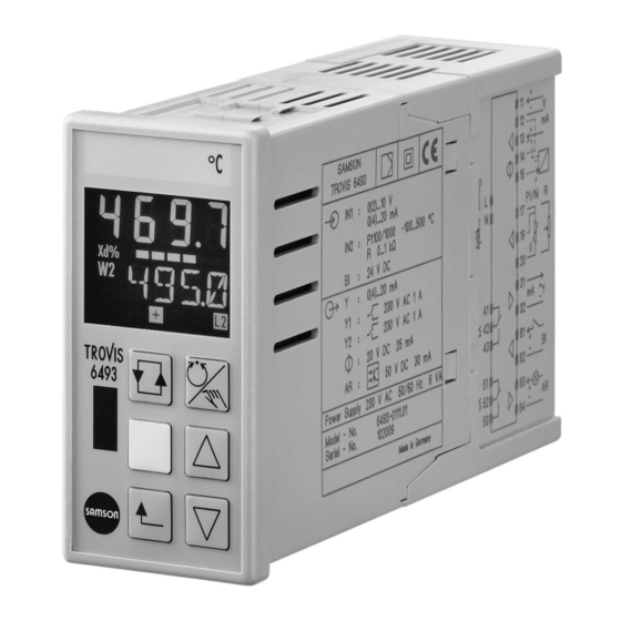
2 Markings on the device 2.1 Housing inscription The details on the device version are lasered onto the nameplate on the side of the controller housing. SAMSON TROVIS 6493 Made in Germany Analog inputs (IN1 and IN2) Binary input (BI) Analog output (Y) -
Page 12: Article Code
Markings on the device 2.2 Article code TROVIS 6493-032 Compact Controller Supply voltage 90 to 250 V AC 24 V AC/DC 2.3 Firmware versions Firmware revisions 4.01 4.02 Internal revisions 4.02 4.03 Internal revisions EB 6493 EN... -
Page 13: Design And Principle Of Operation
Design and principle of operation 3 Design and principle of oper- Analog inputs ation The analog inputs IN1 and IN2 can be ad- justed to the following ranges: The TROVIS 6493 Compact Controller is a − 0 to 20 mA, 4 to 20 mA, 0 to 10 V, 2 to panel-mounted digital controller to automate 10 V the industrial and process plants. - Page 14 Design and principle of operation differential control can be implemented by Binary outputs subtracting two inputs. The binary outputs BO1 and BO2 are de- signed as relays with double-throw contacts. Binary input They can either used as a three-step output, The binary input BI1 is activated by a volt- on/off output or to monitor limit values and age signal (4 to 31 V DC) and can be used...
- Page 15 Design and principle of operation Note TROVIS-VIEW provides a uniform user interface that allows users to configure and parameterize various SAMSON devices using device-specific database modules. The device module 6493 can be downloaded free of charge from our website at u www.samsongroup.com >...
- Page 16 Design and principle of operation EB 6493 EN...
-
Page 17: Technical Data
Design and principle of operation 3.1 Technical data Table 3-1: Technical data · TROVIS 6493 Inputs Analog input IN1 Two analog inputs, optionally for controlled variable Analog input IN2 X or external set point WE 0/4 to 20 mA or 0/2 to 10 V, resistance thermometer Pt 100, Pt 1000, Ni 100, Ni 1000 or potentiometer 1 kΩ... - Page 18 300 V AC, in parallel to each relay contact Isolated transistor output, external supply 3 to Binary output BO3 for fault alarms 50 V DC, max. 30 mA Infrared interface Transmission protocol: SAMSON protocol (SSP) Transmission rate: 9600 bit/s Angle of reflected beam: 50° Distance between infrared adapter and controller: max. 0.7 m...
- Page 19 Design and principle of operation General specifications Display Backlit LCD Display range –999 to +9999; start value, end value and decimal sep- arator can be adjusted Configuration Functions saved in read-only memory for fixed set point and follow-up control, one control circuit Supply voltage 90 to 250 V AC;...
-
Page 20: Dimensions
Design and principle of operation 3.2 Dimensions 158 (6.18) 48 (1.89) 142 (5.59) Fig. 3-2: Dimensions in mm (inch) EB 6493 EN... -
Page 21: Values For Resistance Thermometers
Design and principle of operation 3.3 Values for resistance thermometers Pt 100 sensors (according to DIN EN 60751:2009-05) Temperature °C –100 –90 –80 –70 –60 –50 –40 –30 –20 –10 Resistance Ω 60.26 64.30 68.33 72.33 76.33 80.31 84.27 88.22 92.16 95.09 100.00 Temperature °C +100 +110 Resistance Ω 103.90 107.79 111.67 115.54 119.40 123.24 127.08 130.90 134.71 138.51 142.29 Temperature °C +120 +130... - Page 22 3-10 EB 6493 EN...
-
Page 23: Shipment And On-Site Transport
3. Dispose and recycle the packaging in ac- Risk of damage to the compact controller cordance with the local regulations. due to improper storage. Î Observe the storage instructions. Î Avoid long storage times. Î Contact SAMSON in case of different storage conditions. EB 6493 EN... - Page 24 Shipment and on-site transport Note We recommend regularly checking the com- pact controller and the prevailing storage conditions during long storage periods. Storage instructions − Protect the compact controller against ex- ternal influences (e.g. impact). − Protect the compact controller against moisture and dirt.
-
Page 25: Installation
Installation 5 Installation 5.3 Mounting the compact controller The work described in this section is only to be performed by personnel appropriately The TROVIS 6493 Controller is designed for qualified to carry out such tasks. panel mounting. Î See Fig. 5-1. 5.1 Installation conditions 1. - Page 26 Installation Panel cut-out: 45 x 92 +0.6 +0.8 Dimensions in mm (inch) Mounted depth including terminals: 158 (6.18) Mounting clamps Panel Seal Fig. 5-1: Installation EB 6493 EN...
-
Page 27: Electrical Connection
Installation 5.4 Electrical connection Î Inductances in the control cabinet, e.g. contactor coils, must be equipped with suitable interference suppressors (RC ele- DANGER ments). Risk of fatal injury due to electric shock. Î Control cabinet elements with high field Î For electrical installation, you are re- strength, e.g. - Page 28 Installation Note Generally for potentiometers, we recommend performing a zero and span calibration (see '-CO- ADJ Calibration of analog inputs and analog output' in the 'Operation' section). EB 6493 EN...
- Page 29 Installation Current Current Potentiometers Voltage Resistance Two-wire thermometer transmitter Pt 100/Pt 1000 Ni 100/Ni 1000 1000 0/4...20 mA 4...20 mA 0/2...10 V Three-wire Two-wire Two-wire Three-wire 100 % 100 % – – Analog input – – Supply output 20 V, max. 45 mA 100 % 100 % Analog input...
- Page 30 EB 6493 EN...
-
Page 31: Operation
Operation 6 Operation 6.1 Device overview Controlled variable X W, W2, WE, Y or Xd Limit relay L2 active Three-step output – Limit relay L1 active Three-step output + Fault alarm Hand icon After pressing W2, Y or Xd is dis- played with the value in Bar reading of Xd in % Selector key... -
Page 32: Operating Controls
Operation 6.2 Operating controls The compact controller is operated using the operating keys on the front. Operating keys The function of the keys varies depending on the level/menu which is active. Operating level Configuration level − Open configuration level. − Open menus, functions −... -
Page 33: Display
Operation 6.3 Display Operating level Configuration level Depending on the level selected, the following variables and operating states are shown on the display Controlled variable X Designations, settings and values of functions and parameters (see the 'Design and princi- Value of W, W2, WE, Y or Xd ple of operation' section) Limit relay L2 active No reading... -
Page 34: Infrared Interface
TRO- VIS-VIEW software. It can be accessed from the front of the controller. It is located above the SAMSON logo (see Fig. 6-1). Note Further information on configuration and op- eration using the TROVIS-VIEW software is available in u EB 6661. - Page 35 Operation Holding bracket Order no. 1400-9769 Infrared adapter Order no. 8864-0900 Connector to RS-232 port Fig. 6-2: Connecting the infrared interface Fig. 6-3: USB to RS-232 adapter (order no. 8812-2001) EB 6493 EN...
- Page 36 EB 6493 EN...
-
Page 37: Start-Up And Configuration At The Device
Start-up and configuration at the device 7 Start-up and configuration at the device The work described in this section is only to be performed by personnel appropriately quali- fied to carry out such tasks. Before start-up, make sure the following conditions are met: −... - Page 38 Start-up and configuration at the device Operation in the configuration level Î See Annex A (configuration guide). The settings of the controller in the configuration level are shown in the form of schematic di- agrams: Open configuration level Enter menu Select function/parameter Show setting Activate editing mode for setting/value...
- Page 39 Start-up and configuration at the device EB 6493 EN...
- Page 40 Start-up and configuration at the device EB 6493 EN...
- Page 41 Start-up and configuration at the device EB 6493 EN...
- Page 42 Start-up and configuration at the device EB 6493 EN...
- Page 43 Start-up and configuration at the device EB 6493 EN...
-
Page 44: Configuring The Compact Controller
Start-up and configuration at the device 7.1.1 Configuring the compact controller To set a function or parameter, you need to know the abbreviated code used for the function/ parameter and the menu where it can be found (see example in "Configuration and parame- terization example"... - Page 45 Start-up and configuration at the device Î Open parameter level. Reading: code of the first parameter If you want to configure a different parameter: Î Select parameter. Î Activate editing mode for the parameter. The code of the function parameter blinks. Î...
- Page 46 Start-up and configuration at the device , followed ....Parameter selec- Parameter name Value range 1) tion Proportional-action coefficient [0.1 … 1.0 … 100.0] u KH 6493 Reset time [1 … 120 … 9999 s] [1 … 10 … 9999 s] Derivative-action time TVK1 Derivative-action gain [0.10 …...
- Page 47 Start-up and configuration at the device Î Enter menu. Reading: -CO- and C.PID (first function of CNTR menu) Î Open function. Reading: PI (current setting of C.PID function) Î Activate editing mode for the function. Reading: Prompt for key number Only for operation with key number: Î...
- Page 48 Start-up and configuration at the device Î 2x Change PI to PID control algorithm. Î Confirm setting. The editing mode is exited. Î Change to the parameter level. Reading: -PA- and C.PID/CP.YP blink in alternating sequence Î Open parameter level. Reading: KP (first parameter of C.PID function) 7-12 EB 6493 EN...
- Page 49 Start-up and configuration at the device Î Activate editing mode for the parameter. KP blinks. Î Set proportional-action coefficient KP to 1.5. Î Confirm setting. The editing mode is exited. Note If you want to change other parameters in the func- tion, select the parameters ( ) and repeat the steps (gray background).
-
Page 50: Entering The Key Number
Start-up and configuration at the device 7.2 Entering the key number The TROVIS 6493 Compact Controller can be operated with or without a key number. The controller is set to operate without key number by default. Operation with a key number is only activated after a user-defined key number has been assigned. - Page 51 Start-up and configuration at the device Operation with key number Î Enter valid key number. Î Exit prompt for key number. Note If you enter an incorrect key number, you are prompted again to enter the key number. In this case, 1 appears on the display instead of - - - -.
- Page 52 Start-up and configuration at the device Î Activate prompt for key number. KEY blinks. Î Enter service key number. Note The overriding service key number is specified in the printed document IMPORTANT PRODUCT INFOR- MATION IP 6493, which is supplied with the device. This number allows configuration settings and pa- rameters to be changed regardless of user key num- ber operation.
- Page 53 Start-up and configuration at the device Î Enter your own key number (12 in this example). Î To deactivate operation with key number, select - - - - on the display. Î Exit prompt for key number. The controller returns to the configuration level. Î...
-
Page 54: Tuning The Control Parameters
Start-up and configuration at the device 7.3 Tuning the control parameters The controller must be adapted to the dynamic behavior of the controlled system over the pa- rameters KP, TN and TV to ensure that errors caused by disturbances can be eliminated or largely suppressed. -
Page 55: Tuning According To The Ziegler And Nichols Method
Start-up and configuration at the device Proceed as follows for a P controller 1. Switch to manual mode ( 2. In the CNTR menu, set the function -CO- C.PID = P CP.YP. 3. In the PAR menu, set the parameter KP = 0.1. 4. - Page 56 Start-up and configuration at the device Proceed as follows for a PI controller 1. Switch to manual mode ( 2. In the CNTR menu, set the function -CO- C.PID = PI CP.YP. 3. In the PAR menu, set the parameters KP = 0.1 and TN = 9999 s. 4.
- Page 57 Start-up and configuration at the device 11. Change the set point slightly and check the transient behavior. If necessary, retune KP and TN until the closed loop shows a satisfactory control behavior. Proceed as follows for a P controller 1. Switch to manual mode ( 2.
- Page 58 Start-up and configuration at the device Proceed as follows for a PID controller 1. Switch to manual mode ( 2. In the CNTR menu, set the function -CO- C.PID = PI CP.YP 3. In the PAR menu, set the parameters KP = 0.1 and TN = 9999 s. 4.
-
Page 59: Co- Tune: Start-Up Adaptation
Start-up and configuration at the device 7.3.3 -CO- TUNE: Start-up adaptation The purpose of the adaptation is to quickly determine the best settings for the control param- eters KP, TN and TV with minimum knowledge of the process to be controlled. The control parameters are calculated by the controller from the step response according to the rules introduced by Chien, Hrones and Reswick for the aperiodic control operation and a good reference action. - Page 60 Start-up and configuration at the device 1. In manual mode, set the manipulated variable Y to the operating point so that the con- trolled variable X has the same value as the set point W. 2. Raise the manipulated variable Y, for example by 10 % (with step change value of the manipulated variable Y.JMP = 20 %) and wait until the controlled variable X does not change anymore.
-
Page 61: Start-Up And Configuration With Trovis-View
Start-up and configuration with TROVIS-VIEW 8 Start-up and configuration with TROVIS-VIEW The controller can be configured using the TROVIS-VIEW software. 8.1 Communication 8.1.1 Interface Holding bracket Order no. 1400-9769 Infrared adapter Order no. 8864-0900 Connector to RS-232 port Fig. 8-1: Connecting the infrared adapter Fig. 8-2: USB to RS-232 adapter (order no. - Page 62 Start-up and configuration with TROVIS-VIEW Connecting the infrared adapter 1. Connect the infrared adapter to the computer using the USB to RS-232 adapter. 2. Install the driver for USB to RS-232 adapter. NOTICE An IrDA driver will impair the functioning of TROVIS-VIEW. An IrDA driver must not be installed on the computer on which TROVIS-VIEW is installed.
-
Page 63: Addressing
Start-up and configuration with TROVIS-VIEW 8.1.2 Addressing If there is only one compact controller with an infrared interface in the send/receive range of the infrared adapter, data can be uploaded from the controller or downloaded to it directly. Addressing is not required. If there are several controllers with infrared interfaces at the same point of installation, con- trollers must be addressed using their serial number since only one controller may communi- cate with the computer at one time. -
Page 64: Folders In Trovis-View
Start-up and configuration with TROVIS-VIEW 8.2 Folders in TROVIS-VIEW 8.2.1 Identification The 'Identification' folder contains device-specific data read from the TROVIS 6493 Compact Controller and transferred to the software. The System data (1) and System data (2) fields al- low you to describe a controller by entering short texts comprising a maximum of 30 charac- ters per field (a to z, A to Z, 0 to 9, -). - Page 65 Start-up and configuration with TROVIS-VIEW Set point switchover Conditions for the set point switchover: − The set points involved are activated in the controller (SETP main group), e.g. W = ON and W2 = ON. − If a set point switchover via the binary input BI1 is configured, the binary input must be deactivated during the switchover with TROVIS-VIEW.
-
Page 66: Functions And Parameters
Start-up and configuration with TROVIS-VIEW Note An infrared connection must exist during the switchover of the Current set point. Switchover only functions in offline mode. Manual/automatic switchover To change from manual to automatic operation, set Manual/automatic switch to 'Auto' and transfer the new setting to the controller. -
Page 67: Control Parameters [Par]
Start-up and configuration with TROVIS-VIEW 8.2.3.1 Control parameters [PAR] The Control parameters [PAR] folder corresponds to the PAR main group of the controller. The control parameters KP, TN, TV and Y.PRE are set in this folder. 8.2.3.2 Input [IN] The Input [IN] folder corresponds to the IN main group of the controller. All functions of the two analog inputs IN1 and IN2 are determined in this folder. - Page 68 Start-up and configuration with TROVIS-VIEW Note The units are only intended for documentation and are only saved in the TROVIS-VIEW file and not in the controller itself. Example: User-defined unit for the controlled variable X 1. Double-click Unit X to activate the data point. 2.
-
Page 69: Set Point [Setp]
Start-up and configuration with TROVIS-VIEW 8.2.3.3 Set point [SETP] The Set point [SETP] folder corresponds to the SETP main group of the controller. The set points, set point switchover and set point ramps are set in this folder. In addition, it is possi- ble to assign an input signal to the position feedback of an actuator or to the feedforward control. -
Page 70: Start-Up Adaptation [Tune]
Start-up and configuration with TROVIS-VIEW The 'Reset to default settings' function in the AUX folder causes all parameters, functions and calibration data to be reset to their default settings. The System data (1) and (2) saved in the controller are not cleared. 8.2.3.8 Start-up adaptation [TUNE] The Start-up adaptation [TUNE] folder corresponds to the TUNE main group of the controller. -
Page 71: Process Data [I-O]
Start-up and configuration with TROVIS-VIEW 8.2.3.9 Process data [I-O] The analog and binary input and output variables as well as the controller’s internal vari- ables are displayed in the View process data [I-O] folder. Differences between this folder and the I-O main group of the controller: −... - Page 72 8-12 EB 6493 EN...
-
Page 73: Operation
Operation 9 Operation Operating level While in operation, the controller is in the operating level. Key information on the control process is displayed in this level. The default reading shows the controlled variable X, error Xd, the currently valid set point W, W2 or WE, the active limit relay as well as information on the three-step output, if applicable (see Fig. 9-1). - Page 74 Operation Controlled variable X Cursor key (decrease, After pressing scroll backwards) W2, Y or Xd is displayed W, W2, WE, Y or Xd with the value in 2 Escape key Limit relay L2 active Bar reading of Xd in % Label (exchangeable) Three-step output –...
-
Page 75: Switching Over To Manual Mode And Changing The Manipulated Variable
Operation 9.3 Switching over to manual mode and changing the manipu- lated variable Î Switch to manual mode. icon and the manipulated variable Y are shown on the display. Î Raise the set point. Î Lower the set point. Return to automatic mode. Î... -
Page 76: Aux Menu, -Co- View: Set Viewing Angle Of The Display
Operation 9.5 AUX menu, -CO- VIEW: Set viewing angle of the display The contrast for the top and bottom viewing angle of the display can be changed from Level 1 to Level 10 in the AUX menu. Î See Configuration Manual u KH 6493. The default setting (Level 6) only needs to be changed in extreme installation situations. -CO- VIEW Top/bottom viewing angle of display Level 1... -
Page 77: Co- Ana: Show Analog Inputs And Outputs
Operation 9.6.3 -CO- ANA: Show analog inputs and outputs The analog values are shown in this function. -CO- ANA Analog values Analog input IN1 Analog input IN2 CO.VA Controlled variable before function generation WE.VA WE before function generation FE.CO WE after function generation SP.CO Set point at comparator YPID YPID after limitation YOUT... - Page 78 Operation Calibrating analog inputs: 1. Connect a high-precision meter at the input (IN1, IN2). 2. In the I-O menu, select the ADJ function. 3. Use the cursor keys ( ) to select the input you want to calibrate (AdJ IN1, AdJ IN2). 4.
-
Page 79: Malfunctions
Table 10-1: Error list · Error messages shown on the device Error Possible reasons Recommended action 1 ERR EEPROM access not possible 2 ERR EEPROM cannot be programmed Î Return device to SAMSON for repair. 3 ERR Default calibration lost 4 ERR Functions changed without user interven- Î Check the function settings. tion 5 ERR Parameters changed without user interven- Î... - Page 80 36 ERR Error during adaptation Î Restart start-up adaptation. 256 ERR Basic calibration missing Î Return device to SAMSON for repair. Upper limit violation of rated signal range The error message depends on how -CO- __o1 MEAS is configured (u KH 6493). at analog input IN1 or at analog inputs...
- Page 81 Malfunctions Table 10-2: Error list · Error messages in TROVIS-VIEW Error Possible reasons Recommended action Device does not respond. Interface incorrectly assigned Î Select 'Communication ...' from the 'Options' menu to open the Communication window. Click 'Settings' but- ton and assign a free serial COM port of the computer.
-
Page 82: Error Messages Generated By The Compact Controller
Malfunctions 10.2 Error messages generated by the compact controller Error messages saved in the error memory of the controller can be uploaded and read in TROVIS-VIEW. The internal errors generated by the controller and errors that occurred during a start-up adaptation are shown. The existence of an error message is indicated by the Internal error data point in the 'Oper- ation' and 'Start-up adaptation [TUNE]' folders. -
Page 83: Servicing
− The product warranty becomes void if service or repair work not described in these instruc- tions is performed without prior agreement by SAMSON's After-sales Service. − Only use original spare parts by SAMSON, which comply with the original specifications. Table 11-1: Recommended inspection and testing... - Page 84 11-2 EB 6493 EN...
-
Page 85: Decommissioning
Decommissioning 12 Decommissioning The work described in this section is only to be performed by personnel appropriately qualified to carry out such tasks. DANGER Risk of electric shock while performing electrical connection. For electrical installation, you are required to observe the relevant electrotechnical regula- tions of the country of use as well as the reg- ulations of the local power suppliers. - Page 86 12-2 EB 6493 EN...
-
Page 87: Removal
Removal 13 Removal The work described in this section is only to be performed by personnel appropriately qualified to carry out such tasks. 1. Remove infrared adapter and its bracket, if mounted. 2. Unscrew the threaded rods from the com- pact controller. - Page 88 13-2 EB 6493 EN...
-
Page 89: Repairs
Risk of controller damage due to incorrect service or repair work. Î Do not perform any repair work on your own. Î Contact SAMSON's After-sales Service for repair work. 14.1 Returning devices to SAMSON Defective controllers can be returned to SAMSON for repair. - Page 90 14-2 EB 6493 EN...
-
Page 91: Disposal
Disposal 15 Disposal We are registered with the German national register for waste electric equipment (stiftung ear) as a producer of electrical and electronic equipment, WEEE reg. no.: DE 62194439 Î Observe local, national and internation- al refuse regulations. Î Do not dispose of components, lubricants and hazardous substances together with your other household waste. - Page 92 15-2 EB 6493 EN...
-
Page 93: Certificates
Certificates 16 Certificates The following certificates are included on the next pages: − EU declaration of conformity − TR CU certificate The certificates shown were up to date at the time of publishing. The latest certificates can be found on our website: u www.samsongroup.com >... - Page 94 Für das folgende Produkt / For the following product / Nous certifions que le produit Kompaktregler / Compact Controller / Régulateur compact Typ/Type/Type TROVIS 6493 wird die Konformität mit den einschlägigen Harmonisierungsrechtsvorschriften der Union bestätigt / the conformity with the relevant Union harmonisation legislation is declared with/ est conforme à...
- Page 95 Certificates TR CU certificate EB 6493 EN 16-3...
- Page 96 Certificates 16-4 EB 6493 EN...
- Page 97 Certificates EB 6493 EN 16-5...
- Page 98 16-6 EB 6493 EN...
-
Page 99: Annex A (Configuration Guide)
Annex A (configuration guide) 17 Annex A (configuration guide) The functions and parameters are described in detail in the Configuration Manual u KH 6493. 17.1 Abbreviations Controlled variable Manipulated variable Internal set point W2 Internal set point WE External set point, feedforward control input value, external position feedback Error Minimum value of a variable ... -
Page 100: Configuration List
Annex A (configuration guide) 17.2 Configuration list Î The functions and parameters are described in detail in the Configuration Manual u KH 6493. … …………… or …………………………………… ………………… ……………… Setting Menu Function -CO- options Description of functions Parameter level -PA- 1) Control parameters... - Page 101 Annex A (configuration guide) ……………… …………………… and followed by Parameter selection Parameter name Value range 1) Proportional-action coefficient [0.1 … 1.0 … 100.0] Reset time [1 … 120 … 9999 s] Derivative-action time [1 … 10 … 9999 s] Y.PRE Operating point [–10.0 … 0.0 … +110.0 %] Lower measuring range value [–999.0 … 0.0 … IN1] IN1 Upper measuring range value [ IN1 … 100.0 … 9999] 2) IN1...
- Page 102 Annex A (configuration guide) … …………… or …………………………………… ………………… ……………… Setting Menu Function -CO- options Description of functions Parameter level -PA- 1) off FAIL Switch to manual F01 FAIL With constant output value Y1K1 MAN/FAIL mode in case of F02 FAIL With last manipulated variable value...
- Page 103 Annex A (configuration guide) ……………… …………………… and followed by Parameter selection Parameter name Value range 1) Y1K1 Constant output value [–10.0 … +110 %] parameters parameters TS.X Time constant X filter [0.1 … 1.0 … 100.0 s] TS.WE Time constant WE filter [0.1 … 1.0 … 100.0 s] parameters parameters Lower output signal measuring range value [–999.0 … 0.0 … MAX] 2)
- Page 104 Annex A (configuration guide) … …………… or …………………………………… ………………… ……………… Setting Menu Function -CO- options Description of functions Parameter level -PA- 1) Set point SETP SP.VA on W SP.VA/W Internal set point W Internal set point W2 oFF W2 on W2 P.VA/W2 Input variable WE...
- Page 105 Annex A (configuration guide) ……………… …………………… and followed by Parameter selection Parameter name Value range 1) Internal set point [ WRAN … 0.0 … WRAN] Lower measuring range value W/W2 [–999 … 0.0 … WINT] WINT Upper measuring range value W/W2 [ WINT … 100.0 … 9999] WINT Lower adjustment limit W/W2 [ WINT … 0.0 … WRAN] WRAN Upper adjustment limit W/W2...
- Page 106 Annex A (configuration guide) … …………… or …………………………………… ………………… ……………… Setting Menu Function -CO- options Description of functions Parameter level -PA- 1) Controller CNTR C.PID P CP.YP P behavior C.PID/CP.YP Control algorithm PI CP.YP PI behavior C.PID/CP.YP Pd CP.YP PD behavior...
- Page 107 Annex A (configuration guide) ……………… …………………… and followed by Parameter selection Parameter name Value range 1) Proportional-action coefficient [0.1 … 1.0 … 100.0] Reset time [1 … 120 … 9999 s] Derivative-action time [1 … 10 … 9999 s] TVK1 Derivative-action gain [0.10 … 1.00 … 10.00] Y.PRE Operating point [–10.0 … 0.0 … +110.0] DZXD Dead band error XD [0.0 … 110 %] ...
- Page 108 Annex A (configuration guide) … …………… or …………………………………… ………………… ……………… Setting Menu Function -CO- options Description of functions Parameter level -PA- 1) Output functions SAFE oFF SA.VA Activate constant bi1 SA.VA By binary input BI1 SAFE/SA.VA output value MA.AU...
- Page 109 Annex A (configuration guide) ……………… …………………… and followed by Parameter selection Parameter name Value range 1) Y1K1 Constant output value [–10.0 … 0.0 … +110.0 %] parameters Min. manipulated variable [–10.0 … 0.0 … +110.0 %] Y Max. manipulated variable [–10.0 … +100.0 … +110.0 %] Y TSRA Running time [1 … 9999 s] Y1RA Initial value [–10.0 … 0.0 … +110.0 %] No parameter...
- Page 110 Annex A (configuration guide) … …………… or …………………………………… ………………… ……………… Setting Menu Function -CO- options Description of functions Parameter level -PA- 1) Y.SRC on Y.PID Output YPID noPA Y.SRC/Y.PID Source for analog on Y.X Input X noPA Y.SRC/Y.X output Y on Y.WE...
- Page 111 Annex A (configuration guide) ……………… …………………… and followed by Parameter selection Parameter name Value range 1) parameters CA.K1 Constant 1 [0.0 … 100.0 %] CA.K2 Constant 2 [0.0 … 1.0 … 10.0] CA.K3 Constant 3 [–10.0 … 0.0 … +110.0 %] KPL1 Gain Y+ (BO1) [0.1 … 1.0 … 100.0] KPL2 Gain Y– (BO2) [0.1 … 1.0 … 100.0] TYL1 Cycle duration Y+ (BO1)
- Page 112 Annex A (configuration guide) … …………… or …………………………………… ………………… ……………… Setting Menu Function -CO- options Description of functions Parameter level -PA- 1) Limit relay ALRM LIM1 oFF L1 Limit relay L1 Lo L1.X When X is not reached Hi L1.X When X is exceeded LIM1/L1.X...
- Page 113 Annex A (configuration guide) ……………… …………………… and followed by Parameter selection Parameter name Value range 1) LI.X Limit for X [ IN1 … 100.0 … IN1] 2 3 [ IN2 … 100.0 … IN2] 2 3 LI.WE Limit for WE [ IN1 … 100.0 … IN1] 2 3 [ IN2 … 100.0 … IN2] 2 3 LI.YP Limit for YPID [ Y … 100.0 % … Y] LI.XD Limit for XD [–110.0 … 0.0 … +110.0 %]...
- Page 114 Annex A (configuration guide) … …………… or …………………………………… ………………… ……………… Setting Menu Function -CO- options Description of functions Parameter level -PA- 1) Alarm functions RE.CO F01 MODE Manual, with constant output value RE.CO/MODE Restart conditions F02 MODE Y1K1 RE.CO/MODE...
- Page 115 Annex A (configuration guide) ……………… …………………… and followed by Parameter selection Parameter name Value range 1) Y1K1 Constant output value [–10.0 … 0.0 … +110.0 %] parameters parameters parameters No parameter parameters Default setting is in bold print. EB 6493 EN 17-17...
- Page 116 Annex A (configuration guide) … …………… or …………………………………… ………………… ……………… Setting Menu Function -CO- options Description of functions Parameter level -PA- 1) Start-up adaptation TUNE ADAP oFF ADP.S Adaptation run ADP.S Start ADAP/ADP.S Process data Reading Firmware version S-No...
- Page 117 Annex A (configuration guide) ……………… …………………… and followed by Parameter selection Parameter name Value range 1) Proportional-action coefficient [0.1 … 1.0 … 100.0] Reset time [1 … 120 … 9999 s] Derivative-action time [1 … 10 … 9999 s] Y.JMP Step-change value for adaptation [–100.0 … +20.0 … +100.0 %] Default setting is in bold print. EB 6493 EN 17-19...
-
Page 118: Configuration Protocol
Annex A (configuration guide) 17.3 Configuration protocol Menu Function -CO- Parameters -PA- (see -CO- C.PID) (see -CO- C.PID) (see -CO- C.PID) Y.PRE: (see -CO- C.PID) IN1: IN1: IN1: IN2: IN2: IN2: MEAS: No parameters MAN: Y1K1: (see -CO- SAFE and -CO- RE.CO) CLAS No parameters No parameters... - Page 119 Annex A (configuration guide) Menu Function -CO- Parameters -PA- FUNC K6.X: K6.Y: K7.X: K7.Y: MIN: MAX: K1.X: K1.Y: K2.X: K2.Y: K3.X: K3.Y: K4.X: K4.Y: K5.X: K5.Y: K6.X: K6.Y: K7.X: K7.Y: SETP SP.VA WINT: WINT: WRAN: WRAN: No parameters SP.FU RAMP: TSRA: WIRA: CH.SP:...
- Page 120 Annex A (configuration guide) Menu Function -CO- Parameters -PA- CNTR C.PID: (see PAR) (see PAR) (see PAR) TVK1: (see PAR) DZXD: DZXD: DZXD: SIGN: No parameters D.PID: No parameters CH.CA: CLI.P: CLI.M: M.ADJ: No parameters DIRE: No parameters F.FOR: FC.K1: FC.K2: FC.K3: AC.VA:...
- Page 121 Annex A (configuration guide) Menu Function -CO- Parameters -PA- FUNC: K3.Y: K4.X: K4.Y: K5.X: K5.Y: K6.X: K6.Y: K7.X: K7.Y: Y.VA: No parameters Y.SRC: No parameters CALC: CA.K1: CA.K2: CA.K3: C.OUT: KPL1: KPL2: TYL1: TYL2: TYL1: TYL2: XSDY: B.OUT B.OUT1: No parameters B.OUT2: No parameters ALRM...
- Page 122 Annex A (configuration guide) Menu Function -CO- Parameters -PA- ALRM LIM2: LI.X: LI.WE: LI.YP: LI.XD: LI.HYS: RE.CO: Y1K1: (see -CO- MAN and -CO- SAFE) ST.IN: No parameters KEYL: No parameters VIEW: No parameters FREQ: No parameters No parameters TUNE TUNE: Y.JMP: 17-24 EB 6493 EN...
-
Page 123: Annex B
Annex B 18 Annex B 18.1 Accessories Infrared adapter (RS-232) Order no. 8864-0900 Fixture for infrared adapter Order no. 1400-9769 USB to RS-232 adapter Order no. 8812-2001 Driver for USB to RS-232 adapter u www.samsongroup.com > Service & Support > Download > TROVIS-VIEW > USB/RS-232 adapter (8812-2001) TROVIS-VIEW software (free of charge) u www.samsongroup.com >... -
Page 124: After-Sales Service
E-mail contact You can reach our after-sales service at aftersalesservice@samsongroup.com. Addresses of SAMSON AG and its subsid- iaries The addresses of SAMSON, its subsidiaries, representatives and service facilities world- wide can be found on our website (u www.samsongroup.com) or in all... - Page 128 EB 6493 EN SAMSON AKTIENGESELLSCHAFT Weismüllerstraße 3 · 60314 Frankfurt am Main, Germany Phone: +49 69 4009-0 · Fax: +49 69 4009-1507 samson@samsongroup.com · www.samsongroup.com...
Need help?
Do you have a question about the TROVIS 6493 and is the answer not in the manual?
Questions and answers