Samson TROVIS 5724-8 Series Mounting And Operating Instructions
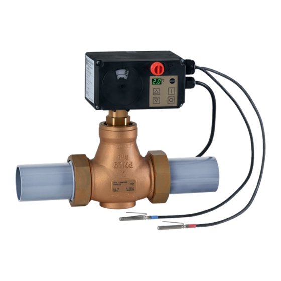
Electric actuator with process controller without failsafe action and with fail-safe action for heating and cooling applications
Hide thumbs
Also See for TROVIS 5724-8 Series:
- Mounting and operating instructions (64 pages) ,
- Mounting and operating instructions (104 pages)
Table of Contents
Advertisement
Quick Links
Advertisement
Table of Contents

Related Manuals for Samson TROVIS 5724-8 Series


Summary of Contents for Samson TROVIS 5724-8 Series
- Page 1 EB 5724-8 EN Translation of original instructions TROVIS 5724-8 Electric Actuator with Process Controller without fail- safe action and TROVIS 5725-8 with fail-safe action For heating and cooling applications Firmware version 1.1x/2.1x Edition August 2019...
- Page 2 Note on these mounting and operating instructions These mounting and operating instructions assist you in mounting and operating the device safely. The instructions are binding for handling SAMSON devices. The images shown in these instructions are for illustration purposes only. The actual product may vary.
-
Page 3: Table Of Contents
Contents Safety instructions and measures ..............5 Notes on possible severe personal injury ............8 Notes on possible personal injury ..............9 Notes on possible property damage ..............10 Markings on the device ................11 Actuator nameplate ..................11 Valve nameplate ..................11 Design and principle of operation ..............12 Fail-safe positions ..................12 Operating controls ..................13 Readings and their meaning .................13... - Page 4 Contents Operation ....................30 Adjusting the set point ..................31 Starting/end closed-loop operation ...............31 Increase/decrease set point ................32 Selecting the external/internal set point ............32 Start and stop program controller ..............33 Manually changing the stem position .............33 Servicing.....................34 Preparation for return shipment ..............34 Malfunctions ....................35 Emergency action ..................35 Decommissioning and removal ..............36...
-
Page 5: Safety Instructions And Measures
Therefore, operators must ensure that the actuator is only used in operating conditions that meet the specifications used for sizing the actuator at the ordering stage. In case operators intend to use the actuator in other applications or conditions than specified, contact SAM- SON. SAMSON does not assume any liability for damage resulting from the failure to use the de- vice for its intended purpose or for damage caused by external forces or any other external factors. Î Refer to the technical data for limits and fields of application as well as possible uses. See section 3.6. - Page 6 − An active blocking protection (A8.3 configuration item = 1, see section 10.2) in the elec- tric actuator with process controller prevents the valve from seizing up. − Upon supply voltage failure, the TROVIS 5725-8 Electric Actuator causes the valve to move to a certain fail-safe position. The fail-safe action of SAMSON actuators is speci- fied on the actuator nameplate. Warning against residual hazards To avoid personal injury or property damage, plant operators and operating personnel must prevent hazards that could be caused in the control valve by the process medium, the operat- ing pressure, the signal pressure or by moving parts by taking appropriate precautions.
- Page 7 The following documents apply in addition to these mounting and operating instructions: − Configuration Manual for TROVIS 5724-8 and TROVIS 5725-8 Electric Actuators with Process Controller u KH 5724-8 − Mounting and operating instructions of the valve on which the electric actuator is mount- ed, e.g. for SAMSON valves: u EB 5861 for Type 3260 Three-way Valve u EB 5863 for Type 3226 Three-way Valve u EB 5866 for Type 3222 Globe Valve u EB 5868 for Type 3213 and Type 3214 Globe Valves...
-
Page 8: Notes On Possible Severe Personal Injury
Safety instructions and measures 1.1 Notes on possible severe personal injury DANGER Risk of fatal injury due to electric shock. Î Before connecting wiring, performing any work on the device or opening the de- vice, disconnect the supply voltage and protect it against unintentional reconnec- tion. Î Only use power interruption devices that are protected against unintentional recon- nection of the power supply. -
Page 9: Notes On Possible Personal Injury
Safety instructions and measures 1.2 Notes on possible personal injury WARNING Crush hazard arising from moving parts. The form-fit version of the electric actuator with process controller contains moving parts (actuator and plug stems), which can injure hands or fingers if inserted into the actuator. Î Do not insert hands or finger into the yoke while the valve is in operation. Î Disconnect the supply voltage before performing any work on the control valve. Î Do not impede the movement of the actuator or plug stem by inserting objects into their path. -
Page 10: Notes On Possible Property Damage
Safety instructions and measures 1.3 Notes on possible property damage NOTICE Risk of actuator damage due to the supply voltage exceeding the permissible tolerances. The electric actuators are designed for use according to regulations for low-voltage in- stallations. Î Observe the permissible tolerances of the supply voltage. Risk of actuator damage due to excessively high tightening torques. -
Page 11: Markings On The Device
Markings on the device 2 Markings on the device 2.2 Valve nameplate See associated valve documentation. 2.1 Actuator nameplate TROVIS 5724-820 Electric Actuator with Process Controller Var.-ID 4150511.04 Serial no. 1085 *000000* F: 500 N s: 12 mm v: 0.18 mm/s U: 230 V f: 50 Hz P: 5 VA... -
Page 12: Design And Principle Of Operation
3.1 Fail-safe positions The electric actuators with process controller are mounted onto SAMSON Types 3222, TROVIS 5724-8 3213, 3214, 2488, 42-36 E, 3226 and The TROVIS 5724-8 Electric Actuator with 3260 Valves as well as Series V2001 Valves Process Controller does not have fail-safe ac- up to valve size DN 50. -
Page 13: Operating Controls
Design and principle of operation 3.2 Operating controls Reading The actual value (process variable) before TROVIS 5724-8: the comparator for controller [1] or [2] is Travel indicator handwheel shown on the display during closed-loop op- eration. The setting is performed in the A3.1 configuration item in TROVIS-VIEW. See sec- tion 10.2. 3.3 Readings and their meaning Non-blinking readings on the display Displayed value (see A.2.2) lower than... -
Page 14: Versions
Design and principle of operation − Programmed function of [O] key activat- No initialization (7) ed by on-site operation. No calibration (8) Stem extension/retraction canceled (9) Manual level active Time Initialization in progress − Program (program controller) active. Update in progress Note Time The number in brackets indicates the priority of the E0 to E9 errors (highest priority = 1). -
Page 15: Accessories
Design and principle of operation 3.5 Accessories − Device version [A] with two-wire con- necting cable (voltage supply) and two Pt 1000 sensors Accessories for communication − Device version [B] with three-wire con- − TROVIS-VIEW software necting cable (voltage supply and switch- The TROVIS-VIEW software can be ing output) and two Pt 1000 sensors downloaded free of charge from our... -
Page 16: Technical Data
Design and principle of operation Accessories for sensors − CrNiMo steel thermowell, G ½, immer- sion length 250 mm, PN 40, order no. − Mounting kit for a Pt 1000 cable sensor 1099-0806 as contact sensor, order no. 8524-0020 − Brass thermowell, G ½, immersion length − Brass thermowell, G ½, immersion length 160 mm, PN 16, order no. 8525-5005 80 mm, PN 16, order no. 1099-0807 − CrNiMo steel thermowell, G ½, immer- − CrNiMo steel thermowell, G ½, immer- sion length 160 mm, PN 40, order no. sion length 80 mm, PN 40, order no. 8525-5011 1099-0805 3.6 Technical data Electric actuator with process 5724-... - Page 17 Design and principle of operation Weight Approx. 1.1 kg · Compliance Operating time Up to 10 years (depending on the operating conditions of the device) We recommend checking whether the device functions properly every 5 years. Intended lifetime Normally 15 years (depending on the operating condi- tions of the device) Maximum storage period 24 months (provided the storage conditions specified in...
- Page 18 Design and principle of operation Switching output Sensors Amperage Max. 1 A Type 5277-2 5277-3 Voltage Depending on the supply volt- Number of Pt 1000 age: 230 V · 120 V resistors Control line Accuracy Class B Version Sensor length 50 mm 50 mm Wire + ↔ Orange + ↔ Red Perm. temperature range –50 to +180 °C coding –...
- Page 19 Design and principle of operation Table 2: Function of the operating keys Function Briefly pressing the key Depending on how A2.1 configuration item is set, a set point, which can be adjust- ed, is displayed (see section 10.2). Briefly pressing the key Depending on how A2.2 configuration item is set, a different value is displayed (see section 10.2). Briefly pressing the key The function depends on how A1.1 configuration item is set (see section 10.2). Key held pressed for three seconds Reading H A Open manual level. Key held pressed for six seconds Reading I n Start initialization (see section 5.4).
-
Page 20: Dimensions In Mm
Design and principle of operation 3.7 Dimensions in mm TROVIS 5724-810/-820 and TROVIS 5725-810/-820 TROVIS 5724-830 and TROVIS 5725-830 Ø15.8 46.5 Ø10 EB 5724-8 EN... -
Page 21: Measures For Preparation
(refer to delivery note). storage. Î Observe the storage instructions. 4.1 Unpacking Î Avoid long storage times. Î Contact SAMSON in case of different storage conditions or longer storage Note times. Do not remove the packaging until immedi- ately before mounting and start-up. -
Page 22: Aligning The Travel Indication Scale
Measures for preparation 4.4 Aligning the travel indica- Î Remove scale, turn it and replace it so that the pin is positioned over the appro- tion scale priate hole (6, 12 or 15) corresponding The travel indication scale has two opposed to the rated travel (6, 1 or 15 mm travel). -
Page 23: Mounting And Start-Up
Mounting and start-up 5 Mounting and start-up 3. Pull plug stem until it reaches the actua- tor stem or extend actuator stem using the handwheel (2). NOTICE 4. Position the clamps of the stem connector Risk of malfunction due to incorrectly per- (16) included in the accessories on the formed start-up. - Page 24 Measures for preparation Force-locking attachment with coupling nut, e.g. Form-fit attachment with stem connector, e.g. with to Type 3222 Valve rod-type yoke on Series V2001 Valve Handwheel (TROVIS 5724-8 on- Actuator stem Coupling nut Rod-type yoke Stem connector Fig. 4: Attaching actuator and valve Fig. 5: Mounting position EB 5724-8 EN...
-
Page 25: Electrical Connection
Mounting and start-up 5.3 Electrical connection Î Install the ready-wired sensors depend- ing on the application. DANGER Risk of fatal injury due to electric shock. All ready-configured applications are de- − Upon installation of the electric cables, you scribed in the Configuration Manual are required to observe the regulations u KH 5724-8. -
Page 26: Starting Initialization
Mounting and start-up 5.4 Starting initialization Pt 1000, The actuator needs to be initialized on start- red marking – ing up the actuator for the first time. Mount Pt 1000, the electric actuator with process controller – blue marking onto the valve before initialization to ensure that the initialization values match the on-site –... -
Page 27: Configuring The Electric Actuator
This configura- The electric actuator with process controller tion manual can be downloaded from the can be connected to a control station over SAMSON website (u www.samsongroup. Modbus and can be configured using TRO- com) and is available in the [?] menu in the VIS-VIEW. Various communications protocol TROVIS-VIEW software. - Page 28 Mounting and start-up Table 3: Communication parameters C P menu Designation Setting Communication unit Bluetooth module not active Bluetooth module active RS-485 module active Communication protocol Modbus RTU slave The following values are automatically set with the 'A P' setting: b d = 96, S t = I n Automatic protocol detection Modbus address 01 ..99 01 to 99 (station address) 00.
-
Page 29: Connection With Control Station
Mounting and start-up No protocol supported Timeout − Setting -2: automatic The external manual level of the communica- The SSP and Modbus protocols are au- tion is monitored by the bus failure monitor- tomatically detected: the interface pa- ing. After a bus failure is detected, automatic rameters are fixed internally to Baud rate operation is reestablished. -
Page 30: Configuration Of The Electric Actuator
Operation 6 Operation Defining Modbus parameters in TROVIS- VIEW software The valve with electric actuator is ready for Î Change parameters in [Service] folder (> use when mounting and start-up have been Communication). completed. 5.6.3 Configuration of the WARNING electric actuator Form-fit version: crush hazard arising from moving parts (actuator and plug stem). -
Page 31: Adjusting The Set Point
Operation 6.1 Adjusting the set point 6.2 Starting/end closed-loop operation Necessary configuration (see section 10.2) − A2.1 = 1 to change the set point at con- Necessary configuration (see section 10.2) troller [1] C1.SP − A1.1 = 1 − A2.1 = 2 to change the set point at con- Start closed-loop operation troller [2] C2.SP Start closed-loop operation. Adjusting the set point Readings: Select the set point reading. 'on' during start-up time. Afterwards, the value resulting from the A3.1 con- Start set point adjustment. -
Page 32: Increase/Decrease Set Point
Operation 6.3 Increase/decrease set 6.4 Selecting the external/in- point ternal set point Necessary configuration (see section 10.2) Necessary configuration (see section 10.2) − A1.1 = 2 And A1.5 = 0 or − A1.1 = 3 And A1.5 = 0 or − A1.1 = 2 and A1.5 = 1 or − A1.1 = 3 and A1.5 = 1 or − A1.1 = 2 and A1.5 = 2 or − A1.1 = 3 and A1.5 = 2 or − A1.1 = 2 and A1.5 = 3 or − A1.1 = 3 and A1.5 = 3 or − A1.1 = 2 and A1.5 = 4 − A1.1 = 3 and A1.5 = 4 Note Note The setting A1.5 = 1, 2, 3 or 4 allows the The setting A1.5 = 1, 2, 3 or 4 allows the operating function to be controlled by the operating function to be controlled by the... -
Page 33: Start And Stop Program Controller
Operation 6.5 Start and stop program 6.6 Manually changing the controller stem position The program controller allows you to define TROVIS 5724-8 only the set point over time (max. 1 week = A manual adjustment of the stem position 10080 min). Additionally, it is possible to only makes sense when the power supply is define the behavior after the program has switched off as the stem position is deter- run. See A0.1 configuration item in sec- mined by the actuator in closed-loop opera- tion 10.2. -
Page 34: Servicing
Servicing 7 Servicing Note The electric actuator with process controller was checked by SAMSON before it left the factory. − The product warranty becomes void if service or repair work not described in these instructions is performed without prior agreement by SAMSON's After-sales Service. -
Page 35: Malfunctions
Î Troubleshooting (see Table 4). Note Emergency action in the event of valve fail- Contact SAMSON's After-sales Service for ure is described in the associated valve doc- malfunctions not listed in the table. umentation. 8.1 Emergency action... -
Page 36: Decommissioning And Removal
Decommissioning and removal 9 Decommissioning and 2. Completely drain the pipelines and valve. removal 3. Disconnect and lock the power supply. 4. If necessary, allow the pipeline and valve DANGER DANGER components to cool down. Risk of fatal injury due to electric shock. 5. -
Page 37: Disposal
You can reach our after-sales service at al refuse regulations. aftersalesservice@samsongroup.com. Î Do not dispose of components, lubricants Addresses of SAMSON AG and its subsid- and hazardous substances together with iaries your other household waste. The addresses of SAMSON, its subsidiaries,... -
Page 38: Configuration And Parameter List
Annex 10.2 Configuration and parameter list Note The default setting depends on the selected system code number. A list of all default settings is available on page 54. CO/PA Function/ Setting/ designation adjustment range I … Inputs and outputs Universal input I1/Universal input I2/Universal input I3 I1/I2/I3 Function 0: None... - Page 39 Annex CO/PA Function/ Setting/ designation adjustment range AI4.COR* Offset AI4 –9.9 to 9.9 % AI4.O1 Output signal, point 1 –50 to 150 °C AI4.I2 Input signal, point 2 0.1 to 100.0 % AI4.O2 Output signal, point 2 –50 to 150 °C Switching output Function None On with LIM1 / Off with lag time On with LIM2 / Off with lag time On at travel > 0 % / Off at 0 % with lag time On at travel < 100 % / Off at 100 % with lag time...
- Page 40 Annex CO/PA Function/ Setting/ designation adjustment range 35: Heating · Follow-up control · Outdoor temperature con- trolled, return flow temperature limitation · External set point decrease with DI4 50: Heating · Override control with minimum selection · System code number Return flow temperature limitation · Internal set point decrease 55: Heating · Override control with minimum selection · Outdoor temperature controlled, return flow tempera- ture limitation · External set point decrease with DI4 60: Cooling · Override control with minimum selection · Differential temperature with two sensors, return flow temperature limitation · Start/stop control sequence 65: Cooling · Override control with minimum selection · Differential temperature with two sensors, return flow temperature limitation · Start/stop control sequence 66: Cooling · Override control for district cooling · Maxi- mum selection of the set point control ·...
- Page 41 Annex CO/PA Function/ Setting/ designation adjustment range Control function Control mode Fixed set point/follow-up Override (MIN selection) Override (MAX selection) Controller [1] active when LIM1 = off / Control- ler [2] active when LIM1 = on Controller [1] active when LIM2 = off / Control- ler [2] active when LIM2 = on Controller [1] active when DI1 = off / Controller [2] active when DI1 = on Controller [1] active when DI2 = off / Controller [2] active when DI2 = on Controller [1] active when DI3 = off / Controller [2] active when DI3 = on Controller [1] active when DI4 = off / Controller [2] active when DI4 = on Cascade >> (increasing/increasing) Direction of action <> (increasing/decreasing) Internal limit LIM1/Internal limit LIM2 LIM1.S/ Source Measured value AI1...
- Page 42 Annex CO/PA Function/ Setting/ designation adjustment range 15: Set point from program controller LIM1.F/ Function None LIM2.F Source (signal) ≤ LIM1 Source (signal) ≤ LIM2 Source (signal) ≥ LIM1 Source (signal) ≥ LIM2 LIM1.P/ Switching point –50 to +150 °C LIM2.P LIM1.H/ Hysteresis 0.5 to 10.0 °C LIM2.H Program controller A0.1 Behavior when program 1: Control active, last set point is retained has elapsed 2: Control active, program is repeated cyclically 3: Control inactive, actuator positioning value is 0 %...
- Page 43 Annex CO/PA Function/ Setting/ designation adjustment range Formula parameters for actual value C1.a/C2.a Factor AI1 –9.0 to +99.0 C1.b/C2.b Factor AI2 –9.0 to +99.0 C1.c/C2.c Factor AI3 –9.0 to +99.0 C1.d/C2.d Factor AI4 –9.0 to +99.0 C1.z/C2.z Divisor 1.0 to 99.0 Set point adjustment C1.2/C2.2 Source...
- Page 44 Annex CO/PA Function/ Setting/ designation adjustment range Error signal C1.3/C2.3 Function 0: Not inverted 1: Inverted by DI1 2: Inverted by DI2 3: Inverted by DI3 4: Inverted by DI4 5: Inverted by LIM1 6: Inverted by LIM2 7: Inverted PID controller C1.KP/ Proportional-action coeffi-...
- Page 45 Annex CO/PA Function/ Setting/ designation adjustment range M ... Actuator Actuator parameters MY.EA End position guiding (stem 0.0 to 49.9 % extends) MY.EE End position guiding (stem 50.0 to 100.0 % retracts) MY.TE Idle time during end posi- 0 to 99 s tion guiding MY.TZ Dead band (switching 0.5 to 5.0 % range) Signal failure...
- Page 46 Annex CO/PA Function/ Setting/ designation adjustment range A ... Operation [I]/[O] setting A1.1 Function No function [I] Start control sequence / [O] Stop control sequence [I] Set point / [O] Set point increase/decrease [I] External set point / [O] Internal set point [I] Start/halt program controller / [O] Cancel pro- gram controller A1.5 Open loop control [I]/[O] keys [I]/[O] keys or DI1 [I]/[O] keys or DI2 [I]/[O] keys or DI3 [I]/[O] keys or DI4 A1.T.ON Start-up time after start 0 to 999 s A1.YP.ON Positioning value during 0.0 to 100.0 % start-up function...
- Page 47 Annex CO/PA Function/ Setting/ designation adjustment range A2.2 [Down] key function Display measured value AI1 Display measured value AI1 after function generation Display measured value AI2 Display measured value AI2 after function generation Display measured value AI3 Display measured value AI3 after function generation Display measured value AI4 Display measured value AI4 after function generation Display actual value before comparator of controller...
-
Page 48: Excerpt From Modbus List
Annex 10.3 Excerpt from Modbus list The firmware version 2.1x of TROVIS 5724-8 and TROVIS 5725-8 Electric Actuators with Process Controller have an integrated RS-485 interface to use the Modbus RTU protocol, which is a master/slave protocol (in which the control station acts as the master and the elec- tric actuator as the slave). The following Modbus functions are supported: Code Modbus function... - Page 49 Annex Transmission range Indicating range Designation Access Start Start Device ID data Device type 5724 5725 5724 5725 Implementation Revision (e.g. rev. 2.00) 9999 1.00 99.99 Serial number, part 1 (four high-order digits) 9999 9999 Serial number, part 2 (four low-order digits) 9999 9999 Firmware version...
- Page 50 Annex Transmission range Indicating range Designation Access Start Start Manual level Manual positioning value (external) 1000 100.0 Set point deviation of the external manual lev- 1000 100.0 Operating values (operating function) Operating function status Operating function cause Program controller set point –500 1500 –50.0...
- Page 51 Annex Transmission range Indicating range Designation Access Start Start Operating values and settings of controller [2] Actual value before comparator of controller –500 1500 –50.0 150.0 [2] (PV[2]) Set point before comparator of controller [2] –500 1500 –50.0 150.0 (SP[2]) Set point deviation of controller [2] (SP[2] – –9999 9999 –999.9 999.9 PV[2]) Positioning value of controller [2] before char- 1000 100.0 acteristic Y[2]...
- Page 52 Annex Designation COILS (1-bit) Access Status 0 Status 1 Limits State of internal limit 1 State of internal limit 2 Limit switches State of limit switch "stem retracted" State of limit switch "stem extended" Switching output Logical state of switching output Switching contact of switching output Enable manual level for switching output Logical state (manual level for switching out-...
- Page 53 Annex Designation COILS (1-bit) Access Status 0 Status 1 EE-Error manufacturing parameters state EE-Error manufacturing parameters cause EE-Error manufacturing parameters state EE-Error transit time cause EE-Error status messages state EE-Error status messages cause EE-Error statistics state EE-Error statistics cause Actions Zero calibration active Initialization active Blocking protection active...
-
Page 54: Default Settings
Annex 10.4 Default settings If a system code number ≠0 is switched to system code number 0, the data of previously se- lected system code number are adopted. Any parameters not used in this configured system are written with the default setting. The electric actuator with process controller is delivered with the system code number 10 (fixed set point control, heating with mean value calculation of two sensors and set point de- crease) set by default. System code number AI1.I1 °C –50 –50 –50 –50 –50 –50 –50... - Page 55 Annex System code number – M4.T – – LIM1.S – – – – – – LIM1.F – – – – – – LIM1.P °C – – – – – – LIM1.H °C – – – – – – LIM2.S – –...
- Page 56 Annex System code number C1.f – – – – – C1.g – – – – – C1.h – – – – – C1.3 C1.KP 40.0 10.0 C1.TN C1.TV C1.Y0 C1.4 C1.YP – – – – – – – C2.1 – –...
- Page 57 Annex System code number C2.3 – – – – – – C2.KP – – – – – – C2.TN – – – – – – C2.TV – – – – – – C2.Y0 – – – – – – C2.4 –...
-
Page 58: Customer-Specific Data
Annex 10.5 Customer-specific data System code number AI1.I1 °C –50 –50 –50 –50 –50 AI1.O1 °C –50 –50 –50 –50 –50 AI1.I2 °C AI1.O2 °C AI2.I1 °C –50 –50 –50 –50 –50 –50 AI2.O2 °C –50 –50 –50 –50 –50 –50 AI2.I2 °C... - Page 59 Annex System code number LIM1.S – – – LIM1.F – – – LIM1.P °C – – – LIM1.H °C – – – LIM2.S – – – LIM2.F – – – LIM2.P °C – – – LIM2.H °C – – – 10.0 C1.1 –...
- Page 60 Annex System code number C1.3 C1.KP 40.0 40.0 10.0 10.0 C1.TN C1.TV C1.Y0 C1.4 C1.YP – – – – – – C2.1 C2.a – – – – – – C2.b – – – – – – C2.c – – – –...
- Page 61 Annex System code number C2.TV C2.Y0 C2.4 C2.YP – – – – – – MY.EA MY.EE 99.0 99.0 99.0 99.0 99.0 99.0 MY.TE MY.TZ A7.1 A7.YP.ERR 100.0 100.0 100.0 100.0 A8.1 A8.2 A8.3 A1.1 A1.5 – – A1.T.ON – – A1.YP.ON 100.0 100.0...
-
Page 62: Electrical Connection
Annex 10.6 Electrical connection UI1 + UI1 – UI2 + UI2 – UI3 + UI3 – UI4 + UI4 – NOTICE The display does not work due to an inter- rupted cable connection. Voltage sup- Î Only open the front housing cover to per- form actions described in these instruc- tions. -
Page 63: Eu Declaration Of Conformity
EN 61000-6-2:2005, EN 61000-6-3:2010, EMC 2014/30/EU (ab/from 2016-04-20) EN 61326:2013 LVD 2006/95/EC (bis/to 2016-04-19) EN 60730-1:2011, EN 61010-1:2010 LVD 2014/35/EU (ab/from 2016-04-20) Hersteller / Manufacturer: SAMSON AKTIENGESELLSCHAFT Weismüllerstraße 3 D-60314 Frankfurt am Main Deutschland/Germany Frankfurt, 2016-04-06 Gert Nahler ppa. Günther Scherer Zentralabteilungsleiter/Head of Department Qualitätssicherung/Quality Managment... - Page 64 EB 5724-8 EN SAMSON AKTIENGESELLSCHAFT Weismüllerstraße 3 · 60314 Frankfurt am Main, Germany Phone: +49 69 4009-0 · Fax: +49 69 4009-1507 samson@samsongroup.com · www.samsongroup.com...
Need help?
Do you have a question about the TROVIS 5724-8 Series and is the answer not in the manual?
Questions and answers