
Related Manuals for Samson TROVIS 5579


Summary of Contents for Samson TROVIS 5579
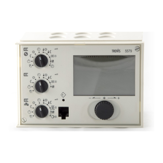
- Page 1 Automation System TROVIS 5500 Heating and District Heating Controller TROVIS 5579 Mounting and Operating Instructions EB 5579 EN Firmware version 1.8x ® Edition April 2009 Electronics from SAMSON...
- Page 2 Moreover, we do not guarantee that the buyer can use the product for an intended purpose. SAMSON rejects any liability for claims by the buyer, especially claims for compensation including lost profits or any other financial loss, except the damage was caused intentionally or by gross negligence.
-
Page 3: Table Of Contents
Contents Contents Operation ....... 7 Operating elements......7 1.1.1 Rotary pushbutton and changeover key . - Page 4 Contents Flash adaptation ......79 5.8.1 Flash adaptation without outdoor sensor (room temperature dependent) . 80 Adaptation .
- Page 5 Contents 7.12.4 Priority over all controllers ..... . 108 7.12.5 Connecting a TROVIS 5570 Room Panel ....108 7.12.6 Display error messages issued by the device bus .
- Page 6 EB 5579 EN...
-
Page 7: Operation
Operation Operation The controller is ready for use with the default temperatures and operating schedules. On start-up, the current time and date need to be set at the controller (–> section 1.5). Operating elements The operating controls are located in the front panel of the controller and protected by a Plexiglas door. -
Page 8: Rotary Switches
Operation 1.1.2 Rotary switches Use the three rotary switches to set the required operating mode (icons on the left) and the relevant parameters (icons on the right) of each control circuit. The top and middle switches are assigned to the heating circuits (see page 161). The rotary switch in the middle is not used in systems without a second heating circuit. -
Page 9: Operating Modes
Operation Rotary switch to set the parameters of the DHW circuit Day set point (DHW temperature) Night set point (DHW temperature sustained value) Times-of-use for heating Party mode Times-of-use for DHW circulation pump Note: If more than one rotary switch is set to position “Parameter“ (right side) at the same time, blinks on the display. -
Page 10: Display
Operation Display During operation, the display indicates the current time as well as information about the op- eration of the controller. The times-of-use are represented by black squares below the row of numbers at the top of the display. Icons indicate the operating status of the controller. STOP 10 11 12 13... -
Page 11: Displaying Data
Operation Displaying data The time, date, public holidays and vacation periods as well as the temperatures measured by the connected sensors and their set points can be retrieved and displayed with the help of the rotary pushbutton. Note: Data can also be viewed in the manual mode. -
Page 12: Setting The Controller Time
Operation Setting the controller time The current time and date need to be set immediately after start-up and after a power failure of more than 24 hours has occurred. This is the case when the time blinks on the display. Proceed as follows: Turn the top rotary switch to position “Controller... -
Page 13: Setting The Times-Of-Use
Operation Setting the times-of-use Three times-of-use can be set for each day of the week. If only one time-of-use is required, the start and stop times of the second time-of-use must be set to identical times. In this case, the third time-of-use is not displayed. If only two times-of-use are required, the start and stop times of the third time-of-use must be set to identical times. - Page 14 Operation Turn appropriate rotary switch to position Proceed as follows: “Times-of-use”. Display shows: 1–7 Select period/day for which the times-of-use are to be 0 1 2 3 4 5 6 7 8 9 10 11 12 13 14 15 16 17 18 19 20 21 22 23 24 valid: 1–7 = every day, 1 = Monday, 2 = Tuesday, ..., 7 = Sunday...
-
Page 15: Setting The Party Mode
Operation Setting the party mode Using the Party mode function, the controller continues or activates the rated operation of the controller during the time when the party timer is active, regardless of the programmed times-of-use. The party timer begins when the rotary switch has been returned to operating mode “Automatic“. -
Page 16: Activating Extended Operating Level
Operation Activating extended operating level After the key number 1999 has been entered, the following information can be viewed and edited after the data points listed in section 1.4 have been displayed: Heat capacity Flow rate Public holidays (can be changed) Vacation periods (can be changed) Valve positions... -
Page 17: Setting Public Holidays
Operation 1.8.1 Setting public holidays On public holidays, the times-of-use specified for Sunday apply. A maximum of 20 public holidays may be entered. Level / Range of values Parameter Public holidays – Extended operating level / 01.01 (1 Jan) to 31.12 (31 Dec) Proceed as follows: In extended operating level, select public holidays. -
Page 18: Setting Vacation Periods
Operation 1.8.2 Setting vacation periods During vacation periods, the controller constantly remains in reduced operation. A maximum of 10 vacation periods can be entered. Each vacation period can be separately assigned to the heating circuits Rk1 to Rk3 and/or the DHW circuit. Level / Range of values Parameter Vacation period (START, STOP) - Page 19 Operation Exit data point for vacation periods. Note: Vacation periods can also be entered in PA5 parameter level (–> section 2.3). Deleting vacation periods: Under data point for vacation periods, select the start date of the period you wish to de- lete.
-
Page 20: Setting Room And Dhw Temperature Set Points
Operation Setting room and DHW temperature set points For the heating circuits, the required room temperatures during the day ( Day set point ) and during the night ( Night set point ) can be set. In the DHW circuit, the temperature you wish the DHW to be heated to can be set. The temperature set points for the different control circuits are set at the rotary switches one after the other: Desired temperature set point... - Page 21 PA2/CO2: Heating circuit Rk2 ( meter bus communication PA3/CO3: Heating circuit Rk3 ( CO7: Device bus PA4/CO4: DHW heating CO8: Initialization of free PA5/CO5: System-wide parameters inputs Anl: System code number Fig. 2 · Level structure of TROVIS 5579 EB 5579 EN...
-
Page 22: Start-Up
Start-up Start-up The modifications of the controller configuration and parameter settings described in this sec- tion can only be performed after the valid key number has been entered. The valid key number for initial start-up can be found on page 179. To avoid unauthorized use of the key number, remove the page or make the key number unreadable. -
Page 23: Activating And Deactivating Functions
Start-up Activating and deactivating functions A function is activated or deactivated in the associated function block. The numbers 0 to 24 in the top row of the display represent the respective function block numbers. When a con- figuration level is opened, the activated function blocks are indicated by a black square on the right-hand side below the function block number. -
Page 24: Changing Parameters
Start-up Deactivate the function block. Display shows: F__ - 0 Confirm settings. If the function block is not closed, further function block parameters can be adjusted. Proceed as follows: Make the required changes and confirm. If applicable, the next function block parameter is displayed. Confirm all parameters to exit the opened function block. -
Page 25: Calibrating The Sensors
Start-up Proceed as follows: Switch to configuration and parameter level. Display shows: 0 0 0 0 Set valid key number. Confirm key number. Display shows: PA1 Select parameter level (-> Fig. 2). Open parameter level. Select desired parameter. Activate editing mode for the parameter. Edit the parameter. - Page 26 Start-up Sensor calibration is to be activated in CO5 via function block F20. An incorrect sensor calibration can be deleted by setting F20 - 0. Proceed as follows: Switch to configuration and parameter level. Display shows: 0 0 0 0 Set valid key number.
-
Page 27: Resetting To Default Values
Start-up Correct measured value. Read the actual temperature directly from the thermometer at the point of measurement and enter this value as the reference temperature. Confirm corrected measured value. Additional sensors are calibrated similarly. Select End . Exit configuration level. Select End . -
Page 28: Manual Operation
Manual operation Manual operation Switch to manual mode to configure all outputs (see wiring diagram in section 11). The manual operation for the different control circuits is set at the rotary switches: Manual operation Rotary switch Position Heating circuit 1* Heating circuit 2* Middle DHW heating/heating circuit 3*... -
Page 29: Systems
Systems Systems 61 different hydraulic schematics are available. The systems can be configured both as primary and secondary systems. The fundamental hy- draulic differences between a primary and a secondary system are illustrated in Fig. 3. 1. A mixing valve replaces the heat exchanger in the heating/DHW circuit 2. - Page 30 Systems Boiler systems: Single-stage boiler systems can be configured to include any system whose heating circuits and DHW circuit include just one heat exchanger. These systems are Anl 1.0, 1.5 to 1.8, 2.x, 3.x, 4.0 to 4.3, 5.x, 6.0, 7.x, 8.x and 9.x. The boiler can be controlled by an on/off output (CO1 ->...
- Page 31 Systems System Anl 1.0 RK1/Y1 RüF1 Default settings CO1 -> F01 - 0 (without RF1) CO1 -> F02 - 1 (with AF1) CO1 -> F03 - 1 (with RüF1) EB 5579 EN...
- Page 32 Systems Systems Anl 1.1 to 1.4 heating Unfold back cover! RK1/Y1 VF1 RüF1 RF1 System Anl 1.1 Anl 1.2 Anl 1.3 Anl 1.4 Type of DHW heating Type 1 Type 2 Type 3 Type 4 XX = Integration of flow sensor VF4 Possible Possible Possible...
- Page 33 Systems Systems Anl 1.5 and 1.7 heating Unfold back cover! RK1/Y1 RüF1 System Anl 1.5 Anl 1.7 Type of DHW heating Type 1 Type 3 Integration of flow sensor VF4 Not possible Not possible Default settings CO1 -> F03 - 1 (with RüF1) CO4 ->...
- Page 34 Systems Systems Anl 1.6 and 1.8 heating Unfold back cover! RK1/Y1 RüF1 Anl 1.6 Anl 1.8 Anl 1.6 Anl 1.8 System With pre-control With pre-control W/o pre-control W/o pre-control Type of DHW heating Type 2 Type 4 Type 2 Type 4 Integration of VF4, UP1 –...
- Page 35 Systems System Anl 1.9 RüF2 RK2/Y2 BE17 System Anl 1.9 with pre-control Anl 1.9 without pre-control Integration of VF4, UP2 Possible Not possible Note – VF2 takes the position of VF4 Default settings CO4 -> F01 - 0 (without SF1) CO4 ->...
- Page 36 Systems System Anl 2.0 RK1/Y1 RüF1 VF1 UP1 Default settings CO1 -> F01 - 0 (without RF1) CO1 -> F02 - 1 (with AF1) CO1 -> F03 - 1 (with RüF1) CO4 -> F01 - 1 (with SF1) CO4 -> F02 - 0 (without SF2) EB 5579 EN...
- Page 37 Systems Systems Anl 2.1 to 2.4 heating Unfold back cover! RK1/Y1 RüF1 System Anl 2.1 Anl 2.2 Anl 2.3 Anl 2.4 Type of DHW heating Type 1 Type 2 Type 3 Type 4 XX = Integration of flow sensor VF4 Not possible Possible Not possible...
- Page 38 Systems System Anl 3.0 RK1/Y1 RK2/Y2 RüF2 RüF1 Default settings CO1 -> F02 - 1 (with AF1) CO1 -> F03 - 1 (with RüF1) CO2 -> F01 - 0 (without RF2) CO2 -> F03 - 0 (without RüF2) EB 5579 EN...
- Page 39 Systems Systems Anl 3.1 to 3.4 heating Unfold back cover! RK1/Y1 RK2/Y2 RüF2 RüF1 System Anl 3.1 Anl 3.2 Anl 3.3 Anl 3.4 Type of DHW heating Type 1 Type 2 Type 3 Type 4 XX = Integration of flow sensor VF4 Not possible Possible Not possible...
- Page 40 Systems System Anl 3.5 RK1/Y1 RüF1 Control and UP1 are only active during the processing for an Note external demand Default settings CO1 -> F03 - 1 (with RÜF1) EB 5579 EN...
- Page 41 Systems System Anl 4.0 RK1/Y1 RK2/Y2 RüF2 RüF1 Default settings CO1 -> F01 - 0 (without RF1) CO1 -> F02 - 1 (with AF1) CO1 -> F03 - 1 (with RüF1) CO2 -> F01 - 0 (without RF2) CO2 -> F02 - 0 (without AF2) CO2 ->...
- Page 42 Systems Systems Anl 4.1 to 4.3 heating Unfold back cover! RK1/Y1 RK2/Y2 RüF2 RüF1 System Anl 4.1 Anl 4.2 Anl 4.3 Type of DHW heating Type 1 Type 2 Type 3 XX = Integration of VF4 Not possible Possible Not possible ZP integration with CO4 ->...
- Page 43 Systems System Anl 4.5 RK1/Y1 RK2/Y2 RüF2 RüF1 Default settings CO1 -> F01 - 0 (without RF1) CO1 -> F02 - 1 (with AF1) CO1 -> F03 - 1 (with RüF1) CO2 -> F01 - 0 (without RF2) CO2 -> F02 - 0 (without AF2) CO2 ->...
- Page 44 Systems System Anl 5.0 RK1/Y1 RK2/Y2 RüF2 RK3/Y3 RüF3 RüF1 Default settings CO1 -> F02 - 1 (with AF1)* CO1 -> F03 - 1 (with RüF1) CO2 -> F01 - 0 (without RF2) CO2 -> F02 - 0 (without AF2 for Rk2)* CO2 ->...
- Page 45 Systems Systems Anl 5.1 and 5.2 heating Unfold back cover! RK1/Y1 RK2/Y2 RüF2 RK3/Y3 RüF3 RüF1 System Anl 5.1 Anl 5.2 Type of DHW heating Type 1 Type 2 XX = Integration of VF4 Not possible Possible ZP integration with CO4 -> F10 –...
- Page 46 Systems System Anl 6.0 RK1/Y1 RK2/Y2 RüF2 RK3/Y3 RüF3 RüF1 Default settings CO1 -> F01 - 0 (without RF1) CO1 -> F02 - 1 (with AF1)* CO1 -> F03 - 1 (with RüF1) CO2 -> F01 - 0 (without RF2) CO2 ->...
- Page 47 Systems Systems Anl 7.1 and 7.2 heating Unfold back cover! RK1/Y1 RK2/Y2 RüF1 RüF2 System Anl 7.1 Anl 7.2 Type of DHW heating Type 1 Type 2 XX = Integration of VF4 Not possible Possible ZP integration with CO4 -> –...
- Page 48 Systems Systems Anl 8.1 and 8.2 DHW heating Unfold back cover! RüF1 RK2/Y2 RK1/Y1 RüF2 System Anl 8.1 Anl 8.2 Type of DHW heating Type 1 Type 2 XX = Integration of VF4 Not possible Possible ZP integration with CO4 -> –...
- Page 49 Systems Systems Anl 9.1 and 9.2 DHW heating Unfold back cover! RK1/Y1 RK3/Y3 RüF3 RK2/Y2 RüF2 RüF1 System Anl 9.1 Anl 9.2 Type of DHW heating Type 1 Type 2 XX = Integration of VF4 Not possible Possible ZP integration with CO4 -> –...
- Page 50 Systems Systems Anl 9.5 and 9.6 heating Unfold back cover! RK1/Y1 RK3/Y3 RüF3 RüF2 RüF1 RF3 UP1 RK2/Y2 System Anl 9.5 Anl 9.6 Type of DHW heating Type 1 Type 2 XX = Integration of VF4 Not possible Possible ZP integration with CO4 -> –...
- Page 51 Systems System Anl 10.0 RK2/Y2 RüF2 RK1/Y1 RüF1 Default settings CO1 -> F01 - 0 (without RF1) CO1 -> F02 - 1 (with AF1) CO1 -> F03 - 1 (with RüF1) CO2 -> F01 - 0 (without RF2) CO2 -> F02 - 0 (without AF2) CO2 ->...
- Page 52 Systems Systems Anl 10.1 to 10.3 DHW heating Unfold back cover! RK1/Y1 RüF1 RK2/Y2 RüF2 System Anl 10.1 Anl 10.2 Anl 10.3 Type of DHW heating Type 1 Type 2 Type 3 XX = Integration of VF4 Possible Possible Possible ZP integration with CO4 ->...
- Page 53 Systems Systems Anl 11.0 and 11.3 DHW heating Unfold back cover! RK2/Y2 RK1/Y1 RüF1 RüF2 System Anl 11.0 Anl 11.3 Type of DHW heating Type 1 Type 3 Integration of VF4 Not possible Not possible ZP integration with CO4 -> –...
- Page 54 Systems System Anl 11.1 RK2/Y2 RüF2 VF2 UP1 RK1/Y1 RüF1 RF1 Default settings CO1 -> F01 - 0 (without RF1) CO1 -> F02 - 1 (with AF1) CO1 -> F03 - 1 (with RüF1) CO4 -> F01 - 1 (with SF1) CO4 ->...
- Page 55 Systems System Anl 11.2 RK2/Y2 RK1/Y1 RüF1 RüF2 Anl 11.2 Anl 11.2 System With pre-control Without pre-control Type of DHW heating Type 2 Type 2 Integration of VF4, UP2 • – ZP integration with CO4 -> Possible Possible F10 - 1 (broken line, see cover) Note –...
- Page 56 Systems System Anl 11.4 RK2/Y2 RK1/Y1 RüF1 RüF2 ZP integration with CO4 -> Possible F10 - 1 (broken line, see cover) Default settings CO1 -> F01 - 0 (without RF1) CO1 -> F02 - 1 (with AF1) CO1 -> F03 - 1 (with RüF1) CO4 ->...
- Page 57 Systems System 11.9 RüF2 RK2/Y2 RK1/Y1 RüF1 BE17 System Anl 11.9 with pre-control Anl 11.9 without pre-control Integration of VF4, UP2 Possible Not possible Note – VF2 takes the position of VF4 Default settings CO1 -> F01 - 0 (without RF1) CO1 ->...
- Page 58 Systems Systems Anl 12.0 and 12.1 RK2/Y2 RK3/Y3 RüF3 VF2 RüF2 RK1/Y1 RüF1 System Anl 12.0 Anl 12.1 Type of DHW heating Type 1 Type 1 Integration of VF2, SLP – • Default settings CO1 -> F02 - 1 (with AF1) - 1 (with AF1) CO1 ->...
- Page 59 Systems System Anl 12.2 RK2/Y2 VF1 UP3 RüF2 RK1/Y1 RüF1 RK3/Y3 RüF3 Anl 12.2 Anl 12.2 System With pre-control Without pre-control Type of DHW heating Type 2 Type 2 Integration of VF4, UP2 – • ZP integration with CO4 -> Possible Possible F10 - 1 (broken line, see cover)
- Page 60 Systems System Anl 12.9 RüF2 RK2/Y2 VF1 UP3 BE17 RK1/Y1 RüF1 RK3/Y3 RüF3 System Anl 12.9 with pre-control Anl 12.9 without pre-control Integration of VF4, UP2 Possible Not possible Note – VF2 takes the position of VF4 Default settings CO1 -> F02 - 1 (with AF1) CO1 ->...
- Page 61 Systems Systems Anl 13.0 and 13.1 RK2/Y2 RK3/Y3 RüF3 RüF2 RK1/Y1 RüF1 System Anl 13.0 Anl 13.1 Type of DHW heating Type 1 Type 1 Integration of VF2, SLP – • Default settings CO1 -> F01 - 0 (without RF1) - 0 (without RF1) CO1 ->...
- Page 62 Systems System Anl 13.2 RK3/Y3 RüF3 RK2/Y2 RüF2 RK1/Y1 RüF1 Anl 13.2 Anl 13.2 System With pre-control Without pre-control Type of DHW heating Type 2 Type 2 Integration of VF4, UP2 • – ZP integration with CO4 -> Possible Possible F10 - 1 (broken line, see cover) Note VF2 takes the position of VF4...
- Page 63 Systems System Anl 13.9 RK2/Y2 RK3/Y3 RüF3 RüF2 BE17 RK1/Y1 RüF1 System Anl 13.9 with pre-control Anl 13.9 without pre-control Integration of VF4, UP2 Possible Not possible Note – VF2 takes the position of VF4 Default settings CO1 -> F01 - 0 (without RF1) CO1 ->...
- Page 64 Systems System Anl 21.0 RK2/Y2 RüF1 RK3/Y3 RK1/Y1 RüF3 RüF2 Default settings CO1 -> F01 - 0 (without RF1) CO1 -> F02 - 1 (with AF1) CO1 -> F03 - 1 (with RüF1) CO3 -> F01 - 0 (without RF3) CO3 ->...
- Page 65 Systems System Anl 21.1 RK1/Y1 RüF1 RK3/Y3 RK2/Y2 RüF2 RüF3 Default settings CO1 -> F01 - 0 (without RF1) CO1 -> F02 - 1 (with AF1) CO1 -> F03 - 0 (without RüF1) CO3 -> F01 - 0 (without RF3) CO3 ->...
- Page 66 Systems System Anl 21.2 RK2/Y2 RüF1 RK3/Y3 RK1/Y1 RüF3 RüF2 System Anl 21.2 with pre-control Anl 21.2 without pre-control Type of DHW heating Type 2 Type 2 Integration of VF4, UP2 • – ZP integration with CO4 -> Possible Possible F10 - 1 (broken line, see cover) Note –...
- Page 67 Systems System Anl 21.9 RK2/Y2 RüF1 RK3/Y3 RK1/Y1 RüF3 RüF2 BE17 System Anl 21.9 with pre-control Anl 21.9 without pre-control Integration of VF4, UP2 Possible Not possible Note – VF2 takes the position of VF4 Default settings CO1 -> F01 - 0 (without RF1) CO1 ->...
- Page 68 Systems System Anl 25.0 RK3/Y3 RüF1 RK2/Y2 RK1/Y1 RüF2 RüF3 Default settings CO1 -> F01 - 0 (without RF1) CO1 -> F02 - 1 (with AF1)* CO1 -> F03 - 1 (with RüF1) CO2 -> F01 - 0 (without RF2) CO2 ->...
-
Page 69: Functions Of The Heating Circuit
Functions of the heating circuit Functions of the heating circuit Which controller functions are available depends on the selected system code number (Anl). Weather-compensated control When weather-compensated control is used, the flow temperature is controlled according to the outdoor temperature. The heating characteristic in the controller defines the flow temper- ature set point as a function of the outdoor temperature (–>... -
Page 70: Gradient Characteristic
Functions of the heating circuit 5.1.1 Gradient characteristic Basically, the following rule applies: a decrease in the outdoor temperature causes the flow temperature to increase. By varying the parameters Gradient and Level , you can adapt the characteristic to your indi- vidual requirements: The gradient needs to be increased if the room temperature [°C]... - Page 71 Functions of the heating circuit Outside the times-of-use, reduced set points are used for control: The reduced flow set point is calculated as the difference between the adjusted values for Day set point (rated room temperature) and Night set point (reduced room temperature). The Max.
-
Page 72: 4-Point Characteristic
Functions of the heating circuit 5.1.2 4-point characteristic The 4-point characteristic allows you to define your own heating characteristic. It is defined by 4 points each for the Outdoor temperature , the Flow temperature, the Reduced flow temperature and the Return flow temperature . The Max. flow temperature and Min. flow temperature parameters mark the upper and lower limits of the flow temperature. -
Page 73: Fixed Set Point Control
Functions of the heating circuit Parameter level / Range of values Parameters Reduced flow temperature Point 1 60 °C PA1, 2, 3 / 5 to 130 °C Point 2 40 °C Point 3 20 °C Point 4 20 °C Return flow temperature Points 1 to 4 65 °C PA1, 2, 3 / 5 to 90 °C Min. -
Page 74: Underfloor Heating/Drying Of Jointless Floors
Functions of the heating circuit Underfloor heating/drying of jointless floors Using function block setting CO1, 2, 3 -> F05 - 1, the respective heating circuit is configured as an underfloor heating circuit. In doing so, the controller at first only limits the value ranges of the heating characteristic gradient and the maximum flow temperature in PA1, 2, 3 pa- rameter levels: Value range of the gradient: 0.2 to 1.0... -
Page 75: Deactivation Depending On Outdoor Temperature
Functions of the heating circuit In systems in which the drying function had to be interrupted due to DHW heating (e.g. Anl 2.1), storage tank charging does not occur while the drying function is active, provided it is not used for frost protection of the storage tank. Note: The function block parameter can only be accessed when the function has started by deactivating the function block and activating it again. -
Page 76: Ot Activation Value In Rated Operation
Functions of the heating circuit temperature of 15 °C to save energy. Nevertheless, remember that the system requires some time in the morning to heat up the building. Parameter level / Range of values Parameter OT deactivation value 15 °C PA1, 2, 3 / –20 to 50 °C in reduced operation 5.4.3 OT activation value in rated operation... -
Page 77: Delayed Outdoor Temperature Adaptation
Terminal 3 Terminal 15 Terminal 16 Terminal 17 Fig. 7 · Wiring plan for Type 5244/5257-5 Room Panel to TROVIS 5579 for Rk1, Rk2 or Rk3 Apart from measuring the room temperature, the Type 5244 Room Panel (PTC sensor) and... -
Page 78: Optimization
Functions of the heating circuit Selection of the operating mode: – Automatic mode – Day mode (rated operation) – Night mode (reduced operation) Set point correction: during rated operation, the room temperature set point can be in- creased or reduced by up to 5 °C using a continuously adjustable rotary knob. When the room sensor is activated, the measured room temperature is displayed with the re- mote operation is connected and activated. -
Page 79: Flash Adaptation
Functions of the heating circuit During the advance heating period and the premature deactivation of the heating system, the icons blink on the display. Outside the times-of-use, the controller monitors the Night set point (reduced room temperature). When the temperature falls below the night set point, the controller heats with the max. -
Page 80: Flash Adaptation Without Outdoor Sensor (Room Temperature Dependent)
Functions of the heating circuit Configuration Functions Room sensors RF1/2/3 CO1, 2, 3 -> F01 - 1 Flash adaptation CO1, 2, 3 -> F09 - 1 20 min Cycle time / 1 to 100 min (gain) / 0 to 25 Rotary switch / Range of values Parameters Day set point... -
Page 81: Adaptation
Functions of the heating circuit Adaptation The controller is capable of automatically adapting the heating characteristic to the building characteristics, provided a gradient characteristic has been set (CO1, 2, 3 -> F11 - 0). The reference room, where the room sensor is located, represents the entire building and is moni- tored to ensure that the room set point ( Day set point) is maintained. - Page 82 Functions of the heating circuit Configuration Functions Pump management – CO5 -> F17 - 1: Speed control released with BA13 = ON switching states of BA13 * CO5 -> F17 - 0: Speed control released with BA13 = OFF Fault indication output CO5 ->...
-
Page 83: Functions Of The Dhw Circuit
Functions of the DHW circuit Functions of the DHW circuit DHW heating in the storage tank system Start storage tank charging Storage tank charging pump Storage tank sensor 1 Circulation pump Hot water Cold water Fig. 8 · Schematics of a storage tank system The controller begins charging the storage tank when the water temperature measured at sensor SF1 falls below the DHW temperature set point by 0.1 °C. - Page 84 Functions of the DHW circuit Time-controlled switchover of storage tank sensors By configuring a second storage tank sensor SF2 over the function block CO4 -> F19 -1, it is possible to determine that the storage tank sensor SF1 is used for day mode in the DHW cir- cuit and that the storage tank sensor SF2 is used for night mode.
-
Page 85: Dhw Circuit Additionally Controlled By A Globe Valve
Functions of the DHW circuit Parameter level / Range of values Parameters Hysteresis** 5 °C PA4 / 0 to 30 °C Charging temperature boost*** 10 °C PA4 / 0 to 50 °C Lag of storage tank charging pump PA4 / 0.1 to 10.0 Parameters serve as limitation of the adjustment range for the DHW temperature to be set at the rotary switch ** Deactivation value T = DHW temperature + hysteresis... -
Page 86: Dhw Heating In The Storage Tank Charging System
Functions of the DHW circuit DHW heating in the storage tank charging system Start storage tank charging Exchanger charging pump Flow sensor Storage tank charging pump Storage tank sensor 1 Storage tank sensor 2 Circulation pump Hot water Cold water Fig. - Page 87 Functions of the DHW circuit Note: The set point in the heat exchanger circuit which is valid at the end of the charging cy- cle will be used again at the beginning of the next cycle. If times-of-use have been set for DHW heating, the DHW temperature set point adjusted at the rotary switch is applied during these times-of-use.
-
Page 88: Dhw Heating In Instantaneous Heating System
Functions of the DHW circuit Parameter level / Range of values Parameters Max. DHW temperature* 60 °C PA4 / 5 to 90 °C Hysteresis** 5 °C PA4 / 0 to 30 °C Charging temperature boost*** 10 °C PA4 / 0 to 50 °C Max. -
Page 89: Dhw Heating With Solar System
Functions of the DHW circuit Note: The Flow temperature set point upstream of the heat exchanger valid after hot water tapping is finished is used as a reference the next time hot water is tapped. Outside the time-of-use of DHW heating, the hot water is regulated to the Sustained DHW temperature . Configuration Functions Water flowmeter... -
Page 90: Intermediate Heating Operation
Functions of the DHW circuit Parameter level / Range of values Parameters Solar pump ON 10 °C PA4 / 1 to 30 °C Solar pump OFF 3 °C PA4 / 0 to 30 °C Max. storage tank temperature 80 °C PA4 / 20 to 90 °C Intermediate heating operation This function is only available in systems Anl 2.x, 4.1 to 4.5, 8.x, 9.5 and 9.6. -
Page 91: Circulation Pump Operation During Storage Tank Charging
Functions of the DHW circuit Circulation pump operation during storage tank charging With the setting CO4 -> F11 - 1, the circulation pump continues operation according to the programmed time schedule even during storage tank charging. With the setting CO4 -> F11 - 0, the circulation pump is switched off as soon as the storage tank charging pump is activated. -
Page 92: Set-Back Operation
Functions of the DHW circuit 6.8.2 Set-back operation In all systems with DHW heating and at least one heating circuit with control valve, DHW heating can be given priority by applying set-back operation. With the setting CO4 -> F08 - 1, the charging temperature can be monitored in the DHW circuit. In systems without the sensor VFx in the DHW circuit (e.g. - Page 93 Functions of the DHW circuit SF1, has reached the adjusted Disinfection temperature, provided disinfection has not been terminated because the Stop time has been reached. The Hold time of disinfection temperature determines how long the disinfection temperature must be maintained within the adjusted time period to rate the process successful. If the Hold time of disinfection temperature is set to a value other than 0, no intermediate heating oper- ation takes place during thermal disinfection.
- Page 94 Functions of the DHW circuit Configuration Functions Storage tank sensor SF1 CO4 -> F01 - 1 Thermal disinfection CO4 -> F14 - 1 Day of the week / 1–7, 1, 2, ..., 7 with 1–7 = every day, 1 = Monday, ..., 7 = Sunday 0:00h Start time / 0:00h to 23:45h;...
-
Page 95: System-Wide Functions
System-wide functions System-wide functions Automatic summer time/winter time changeover The clock is automatically adjusted on the last Sunday in March at 2.00h and on the last Sunday in October at 3.00h. Configuration Functions CO5 -> F08 - 1 Summer time/winter time changeover Frost protection Frost protection measures are taken when the outdoor temperature falls below the Frost pro- tection limit. -
Page 96: Forced Operation Of The Pumps
System-wide functions Forced operation of the pumps When the heating circuit pumps have not been activated for 24 hours, forced operation of the pumps is started between 12.02h and 12.03h. This is done to avoid that the pumps get stuck when they are not operated for a longer period of time. In the DHW circuit, the circula- tion pump is operated between 12.04h and 12.05h, the other pumps between 12.05h and 12.06h. -
Page 97: Condensate Accumulation Control
System-wide functions Note: If CO5 -> F00 - 1 is indicated, access to the return flow, flow rate and heat capacity settings are locked. Configuration Functions Return flow sensors RüF1/2/3 CO1, 2, 3, 4 -> F03 - 1 Limiting factor / 0.1 to 10.0 Return flow temperature CO5 ->... -
Page 98: Three-Step Control
System-wide functions Note: The condensate accumulation control function can only be activated when no on/off control has been configured, i.e. when CO1, 2, 3, 4 -> F12 - 1 applies. Three-step control The flow temperature can be controlled using a PI algorithm. The valve reacts to pulses that the controller sends when a system deviation occurs. -
Page 99: Continuous Control
System-wide functions Continuous control The flow temperature can be controlled using a PID algorithm. The valve receives an analog 0 to 10 V signal. When a system deviation occurs, the proportional component immediately causes the 0 to 10 V signal to change (the greater K , the greater the change). -
Page 100: Processing Of External Demand In Rk1
System-wide functions Release controller at BE15 CO5 -> F15 - 1* *bE = 1, 0 7.10 Processing of external demand in Rk1 The controller can process binary or analog requests for an externally required signal by a more complex secondary system, provided the following requirements are met: the system is configured without solar system and an analog request can be assigned to “0 to 10 V corre- sponds with 0 to 120 °C flow temperature“. -
Page 101: Flow Rate/Capacity Limitation In Rk1
System-wide functions Parameter level / Range of values Parameter Set point for binary demand processing 40 °C PA1 / 5 to 130 °C Processing of external demand with a 0 to 10 V signal Regardless of the operating mode set for control circuit Rk1– except manual mode –, at least the flow temperature corresponding with the 0 to 10 V signal connected to terminals 17/18 is regulated by the controller. -
Page 102: Limitation Using Pulse Input
System-wide functions 7.11.1 Limitation using pulse input Depending on the operating situation, a heat meter with pulse output connected to input WMZ/Bed (terminals 17/19) can be used to limit either the flow rate or the capacity in the system. All limit values are given in the unit “pulses per hour“ [pulse/h]. As a result, the con- troller does not distinguish between a flow rate pulse signal or a capacity pulse signal. -
Page 103: Limitation Using 0/4 To 20 Ma Signal
System-wide functions 7.11.2 Limitation using 0/4 to 20 mA signal Depending on the operating situation, a heat meter at input WMZ/Bed (terminals 17/19) with a 0/4 to 20 mA output (connected in parallel to input WMZ/Bed using 50 Ω) can be used to limit the flow rate in the system. -
Page 104: Limitation Of The Calculated Capacity
System-wide functions Parameter level / Range of values Function Creep feed rate limitation CO5 -> F12 - 1 bE = 0, 1 7.11.4 Limitation of the calculated capacity The controller is able to calculate the heat capacity used in the system and to limit it depend- ing on the operational circumstances. -
Page 105: Device Bus
Using the device bus, it is possible to connect up to 32 device from the Series 55xx. For con- nection, the TROVIS 5579 Controller is, above all, equipped with the terminals 29/30. No attention must be paid to the polarity of the device bus wiring. - Page 106 System-wide functions The primary controller compares the received requested demands and its own requested de- mands and supplies the system with the required flow temperature – if necessary increased by the value of the Set point boost of primary exchanger control parameter. Note: Overheating may occur in heating circuits of the primary controller without control valve.
-
Page 107: Sending And Receiving Outdoor Temperatures
System-wide functions used by the primary controller. Nevertheless, if the Priority for external demand function is activated, the external demand is also processed during storage tank charging. Configuration Function Priority for external demand CO4 -> F16 - 1 7.12.2 Sending and receiving outdoor temperatures Controllers equipped with one (two) outdoor sensor(s) can be configured to supply other controllers with the measured outdoor temperature(s) over the device bus. -
Page 108: Priority Over All Controllers
*Register no. / 5 to 64 7.12.5 Connecting a TROVIS 5570 Room Panel A TROVIS 5570 Room Panel (accessory) can be connected to the TROVIS 5579 Controller to measure the room temperature and for remote operation of a heating circuit. The room panel enables direct access to the operating mode and controller time settings as well as to all relevant parameters of a heating circuit. -
Page 109: Display Error Messages Issued By The Device Bus
System-wide functions TROVIS 5570 TROVIS 5579 Y COM 12...26.5V AC/ 0...10V 15...36V DC 0...10V 0...10V COM BA12, BA13 Pump management - COM BA12 On/off BA13 Speed Fig. 12 · Connecting the TROVIS 5570 Room Panel to the controller Configuration Functions Device bus CO7 ->... -
Page 110: Requesting Demand Over A 0 To 10 V Signal
Anl 10.0. Otherwise, the heating circuit Rk1 of system Anl 10.0 in the controller processing the request would process the request of the second controller. In this case, configure system Anl 5.0 (TROVIS 5579 only) in the controller processing the re- quest. Configuration... -
Page 111: Feeder Pump Operation
System-wide functions Configuration Function Room sensor RF1, 2, 3 CO1, 2, 3 -> F01 - 0 Exceptions: CO1 -> F01 - 1 and CO7 -> F03-1 CO1 -> F01 - 1 and CO7 -> F04-1 CO1 -> F01 - 1 and CO7 -> F05-1 7.15 Feeder pump operation In systems Anl 3.0, 5.0, 7.x and 12.x, the feeder pump UP1 only starts to operate in the de- fault setting when a flow temperature demand of a secondary controller exists. - Page 112 System-wide functions Proceed as follows: Switch to configuration and parameter level. Display shows: 0 0 0 0 Set key number 1995. Confirm key number. Adjust valid key number. Confirm key number. Key number blinks. Adjust desired custom key number. Confirm custom key number. This new key number is now valid.
-
Page 113: Operational Faults
Operational faults Operational faults A sensor failure is indicated by the blinking icon on the display. In addition, the display is illuminated for 1 second in intervals of 10 seconds when a sensor malfunction persists. The “Error“ message is displayed immediately. Press the rotary pushbutton to open the error level. -
Page 114: Sensor Failure
Operational faults Sensor failure According to the error list, sensor failures are indicated by displaying “Err 1“ message in the error level. For detailed information, exit error level and view the different temperature val- ues in the operating level: each sensor icon displayed together with 3 horizontal lines instead of the measured value indicates a defective sensor. -
Page 115: Error Status Register
Operational faults Configuration Functions Fault indication output BA13 CO5 -> F07 - 1 bA = 1, 0 Error status register The error status register is used to indicate controller or system errors. In modem operation mode when the controller connects to the building control system (GLT) both when an error is detected and when it has been corrected, each change in the status of the error status regis- ter causes the controller to dial the control system. -
Page 116: Sending Text Messages In Case Of Error
[Phone no. of the controller] Controller fault TROVIS 5579 # [controller ID of the faulty controller] The time stamp [Date], [Time] is added by the text messaging center, not by the controller. If an error message is transmitted over the device bus to a controller equipped with a dial-up modem, the controller ID of the faulty controller is sent, instead the controller ID of the “mo-... - Page 117 Operational faults Note: The controller ID is indicated in the extended operating level under Info 2 (first value in the sequence). When Modbus is activated and, at the same time, the dial-up in case of error is released, the connection with the building control station is established first, and then the text message is sent.
-
Page 118: Communication
Communication Communication Using the serial system bus interface, the TROVIS 5579 Heating and District Heating Control- ler can communicate with a building control system. In combination with a suitable software for process visualization and communication, a complete control system can be imple- mented. -
Page 119: System Bus Interface
Communication Note: Regardless of whether communication is established using a modem or data cable, the operating software can be updated using the serial system bus interface, provided Modbus has been activated (CO6 -> F01 - 1). RS-232 system bus interface When looking onto the controller front, the system bus connection is located on the left side inside the controller housing (RJ-45 jack). -
Page 120: System Bus Interface With Rs-232/Rs-485 Cable Converters (For Two-Wire And Four-Wire Bus)
Communication Parameter level / Range of values Parameters* Station address (ST.-NR) PA6 / 1 to 247 with CO6 -> F02 - 1: 1 to 32000 Baud rate (BAUD) 9600 PA6 / 19200, 9600 Cyclical initialization (I) 30 min PA6 / 1 to 255 min Modem dialing pause (P) 5 min PA6 / 0 to 255 min... -
Page 121: Description Of Communication Parameter Settings
Communication the control system in dynamic processes can be limited with regard to time using the Control system monitoring function. While valid Modbus requests are registered, the controller resets the time monitoring. Never- theless, after 30 minutes have elapsed, all level bits are re-initialized to “autonomous“ when an error has occurred. -
Page 122: Meter Bus Interface
CO6 -> F04 - 1 is activated. Meter bus interface With the help of an optional, retrofittable meter bus plug-in module, the TROVIS 5579 Heating and District Heating Controller can communicate with up to 6 heat and water meters according to EN 1434-3. A flow rate or capacity limitation is possible on the basis of the values measured at heat meter WMZ1. -
Page 123: Activating The Meter Bus
Communication 9.4.1 Activating the meter bus To successfully transfer data from the heat meter to the controller, the heat meter must use a standardized protocol in accordance with EN 1434-3. It is not possible to make a general statement about which specific data can be accessed in each meter. For details on the differ- ent meter makes, refer to the technical documentation TV-SK 6311. -
Page 124: Flow Rate/Capacity Limitation Using Meter Bus
Communication Configuration Functions Meter bus CO6 -> F10 - 1 Meter bus address WMZ 1 to 6 (ST.-NR) / 0 to 255 1434 Model code WMZ 1 to 6 / 1434, CAL3, APAtO, SLS Reading mode WMZ 1 to 6 / 24h, CONT, CoiL Tariff function option HT/NT, only selectable for WMZ1 on setting “1434”... - Page 125 Communication trol heating and DHW heating – the Max. limit value for heating and the Max. limit value for DHW have to be set. The Limiting factor determines how strongly the controller responds when the limit values are exceeded in either direction. In extended operating level, the data point Flow rate [m /h] is placed first when flow rate limitation is activated.
- Page 126 Communication Configuration Functions Meter bus CO6 -> F10 - 1 Meter bus address WMZ 1 to 6 (ST.-NR) / 0 to 255 1434 Model code WMZ 1 to 6 / 1434, CAL3, APAtO, SLS Reading mode WMZ 1 to 6 / 24h, CONT, CoiL Capacity limitation in Rk1 using CO6 ->...
-
Page 127: Memory Module
The use of a memory module (order no. 1400-9379) is particularly useful to transfer all data from one TROVIS 5579 Controller to several other TROVIS 5579 Controllers. The memory module is plugged into the RJ-45 jack integrated into the front panel. Once the module has been connected, “79 SP“... -
Page 128: Installation
Installation Installation The controller consists of the housing with the electronics and the back panel with the termi- nals. It is suitable for panel, wall and top hat rail mounting (Fig. 15) Panel mounting 1. Remove both screws (1). 2. Pull apart the controller housing and the back panel. 3. - Page 129 Installation Panel mounting Back of the controller Controller housing Wall mounting Top hat rail mounting Dimensions in mm W x H x D = 144 x 98 x 81 Fig. 15 · Installation EB 5579 EN...
-
Page 130: Electrical Connection
Electrical connection Electrical connection Caution! For electrical installation, you are required to observe the relevant electrotechnical regula- tions of the country of use as well as the regulations of the local power suppliers. Make sure all electrical connections are installed by trained and experienced personnel! Notes on installing the electrical connections Install the 230 V power supply lines and the signal lines separately! To increase noise im- munity, observe a minimum distance of 10 cm between the lines. - Page 131 Electrical connection EB 5579 EN...
- Page 132 Cables with a minimum cross-section of 2 x 0.5 mm² can be connected to the terminals at the back panel of the housing. Connecting the water flowmeter (order no. 1400-9246) A power supply unit and a 4.7 kΩ resistor are required for the water flowmeter to function. Water flowmeter TROVIS 5579 brown/ white green black 4.7 kΩ...
-
Page 133: Appendix
Appendix Appendix 12.1 Function block lists CO1: Heating circuit Rk1 (not system Anl 1.9) Comment Function block parameters / Range of values (default) F Function 01 Room sensor RF1 Not in Anl CO1 -> F01 - 1: Temperature display and input FG1 for 1.5-1.8, Type 5244/5257-5 Room Panel active 3.x, 5.x,... - Page 134 Appendix Comment Function block parameters / Range of values (default) F Function 09 Flash adaptation Not in Anl CO1 -> F09 - 1: Only with CO1 -> F01 - 1 1.5-1.8, Function block parameters: 3.x, 7.x, Cycle time / 1 to 100 min (20 min) 9.x, 12.x (gain) / 0 to 25 (0) 10 Reserved...
- Page 135 Appendix Comment Function block parameters / Range of values (default) F Function 17 Processing of CO1 -> F17 - 1: Only with • CO1 -> F15 - 1 Not in external demand, • CO1 -> F16 - 0 systems binary Options bE / 1, 0 (1) with solar circuit or...
- Page 136 Appendix Comment Function block parameters / Range of values (default) F Function 05 Underfloor heating All* CO2 -> F05 - 1: Limitation of the adjustment ranges Drying of jointless Function block parameters: floors Start temperature / 20 to 60 °C (25 °C) Temperature rise / 1 to 10 °C/24 h (5 °C/24 h) Maximum temperature / 25 to 60 °C (45 °C) Maintaining time of max.
- Page 137 Appendix Comment Function block parameters / Range of values (default) F Function 14 Release Rk2 All* CO2 -> F14 - 1: FG2 has no function at BE16 Select bE / 1, 0 (1) F Function block number, WE Default value, Anl System code number CO3: Heating circuit Rk3 (systems Anl 5.x, 6.0, 9.x, 12.x, 13.x, 21.x and 25.0)* Comment Function block parameters / Range of values (default)
- Page 138 Appendix Comment Function block parameters / Range of values (default) F Function 09 Flash adaptation All* CO3 -> F09 - 1: Only with CO3 -> F01 - 1 Function block parameters: Cycle time / 1 to 100 min (20 min) (gain) / 0 to 25 (0) 10 Reserved 11 4-point...
- Page 139 Appendix CO4: DHW heating (Anl 1.1–1.8, 2.x, 3.1–3.4, 4.1–4.5, 5.1–5.2, 7.x, 8.x, 9.x, 10.1–10.3, 11.x, 12.x, 13.x, 21.x )* Comment Function block parameters / Range of values (default) F Function 01 Storage tank CO4 -> F01 - 0 (not in Anl 11.0, 11.3, 12.0, 13.0, 21.0): sensor SF1 Storage tank thermostat, only with CO4 ->...
- Page 140 Appendix Comment Function block parameters / Range of values (default) F Function 06 Parallel pump 2.1–2.4, CO4 -> F06 - 1: Function block parameters: operation 4.1–4.5 Stop parallel pump operation in case of deviation / 0 to 10 min (10 min) 8.x, 9.5, Flow limit temp.
- Page 141 Appendix Comment Function block parameters / Range of values (default) F Function 12 Control mode 1.9, 7.x, CO4 -> F12 - 1: With [Rk2] three-step control three-step [Rk2] 8.x, 9.x, With [Y2] 0 to 10 V control 0 to 10 V [Y2] 11.x, 12.x, Function block parameters: 13.x, 21.x...
- Page 142 Appendix Comment Function block parameters / Range of values (default) F Function 18 BA12 ON during All* CO4 -> F18 - 1: Only with CO4 -> F17 - 0 DHW demand 19 Time-controlled Not Anl CO4 -> F19 - 1 only with CO4 -> F02 - 1 switchover of 1.9, 11.0, SF1 for day mode and SF2 for night mode.
- Page 143 Appendix CO5: System-wide functions (all systems) If CO5 -> F00 - 1 is indicated, access to the return flow, flow rate and heat capacity settings are locked. Comment Function block parameters / Range of values (default) F Function 01 Sensor calibration CO5 ->...
- Page 144 Appendix Comment Function block parameters / Range of values (default) F Function 10 Flow rate limitation Not in CO5 -> F10 - 1: Only with • CO5 -> F11 - 0 (capacity limitation) systems • CO6 -> F12 - 0 in Rk1 with pulses with solar Input “WMZ/Bed“...
- Page 145 Appendix Comment Function block parameters / Range of values (default) F Function 17 Pump management Not Anl CO5 -> F17 - 1: Speed control released when BA13 = ON, - switching state of 1.5-1.9, only when CO5 -> F07 - 0 BA13 3.5, 7.x CO5 ->...
- Page 146 Appendix Comment Function block parameters / Range of values (default) F Function 06 Dial-up also upon CO6 -> F06 - 1: Dial-up to GLT also to indicate that an error corrected error has been corrected, only with CO6 -> F03 - 1 07 Control system CO6 ->...
- Page 147 Appendix CO7: Device bus (all systems, F02, F03, ... only with CO7 -> F01 -1) Comment Function block parameters / Range of values (default) F Function 01 Device bus CO7 -> F01 - 1: Device bus active Function block parameter: Device bus address /Auto*, 1 to 32 (32) *Auto = controller automatically searches for free device bus address in the system...
- Page 148 Appendix Comment Function block parameters / Range of values (default) F Function 10 Send flow set point CO7 -> F10 - 1: In systems Anl 1.5–1.8, 2.x, 3.1–3.4, 4.1–4.3, 7.x, 8.x, the storage tank charging set point is sent during DHW heating Function block parameter: Register no.
- Page 149 Appendix Comment Function block parameters / Range of values (default) F Function 22 Receive release of CO7 -> F22 - 1: Function block parameter: Register no. / 5 to 64 (32) 23 Receive release of CO7 -> F23 - 1: Function block parameter: Register no.
- Page 150 Appendix CO8: Initialization of free inputs (all systems) Comment Function block parameters / Range of values (default) F Function 01 bE1 in ESR CO8 -> F01- 1: Function block parameter: Error message to error status register with bE state / 1, 0; no error message / –...
- Page 151 Appendix Comment Function block parameters / Range of values (default) F Function 15 bE15 in ESR CO8 -> F15 - 1: Function block parameter: Error message to error status register with bE state / 1, 0; no error message / – – – (1)) 16 bE16 in ESR CO8 ->...
-
Page 152: Parameter Lists
Appendix 12.2 Parameter lists PA1 ( ): Parameter level Heating circuit Rk1 PA2 ( ): Parameter level Heating circuit Rk2 PA3 ( ): Parameter level Heating circuit Rk3 Parameter designation Range of values (default) Display Gradient, flow 0 1 2 3 4 5 6 7 8 9 10 11 12 13 14 15 16 17 18 19 20 21 22 23 24 0.2 to 3.2 (1.8) (with CO1, 2, 3 ->... - Page 153 Appendix Parameter designation Range of values (default) Display 0 1 2 3 4 5 6 7 8 9 10 11 12 13 14 15 16 17 18 19 20 21 22 23 24 4-point characteristic Press rotary pushbutton to set the following parameters outdoor temperature, flow temperature, reduced flow temperature and...
- Page 154 Appendix Parameter designation Range of values (default) Display 0 1 2 3 4 5 6 7 8 9 10 11 12 13 14 15 16 17 18 19 20 21 22 23 24 OT deactivation value in rated operation °C 0 to 50 °C (22 °C) STOP 0 1 2 3 4 5 6 7 8 9 10 11 12 13 14 15 16 17 18 19 20 21 22 23 24...
- Page 155 Appendix Parameter designation Range of values (default) Display 0 1 2 3 4 5 6 7 8 9 10 11 12 13 14 15 16 17 18 19 20 21 22 23 24 Return flow temperature foot °C 5 to 90 °C (65 °C) 0 1 2 3 4 5 6 7 8 9 10 11 12 13 14 15 16 17 18 19 20 21 22 23 24 Max.
- Page 156 Appendix PA4: Parameters DHW heating Display Parameter designation Range of values (default) 0 1 2 3 4 5 6 7 8 9 10 11 12 13 14 15 16 17 18 19 20 21 22 23 24 Min. DHW temperature °C 5 to 90 °C (40 °C) Max.
- Page 157 Appendix Display Parameter designation Range of values (default) 0 1 2 3 4 5 6 7 8 9 10 11 12 13 14 15 16 17 18 19 20 21 22 23 24 Max. charging temperature (only with VF4) °C 20 to 130 °C (80 °C) Lag of storage tank charging pump 0 1 2 3 4 5 6 7 8 9 1 0 11 12 13 14 15 16 17 18 19 20 21 22 23 24...
- Page 158 Appendix Display Parameter designation Range of values (default) 0 1 2 3 4 5 6 7 8 9 10 11 12 13 14 15 16 17 18 19 20 21 22 23 24 Max. storage tank temperature °C 20 to 90 °C (80 °C) STOP PA5: System-wide parameters (all systems) Display...
- Page 159 Appendix PA6: Modbus parameters (all systems) Display Parameter designation Range of values (default) Station address 0 1 2 3 4 5 6 7 8 9 10 11 12 13 14 15 16 17 18 19 20 21 22 23 24 1 to 247 (255) ST.-NR (with CO6 ->...
- Page 160 Appendix Display Parameter designation Range of values (default) 0 1 2 3 4 5 6 7 8 9 10 11 12 13 14 15 16 17 18 19 20 21 22 23 24 Modem time-out (t) 1 to 255 min (5 min) 0 1 2 3 4 5 6 7 8 9 10 11 12 13 14 15 16 17 18 19 20 21 22 23 24 Number of redialing attempts to building control station (C) 1 to 255 (15)
-
Page 161: Assignment Of The Rotary Switches
Appendix 12.3 Assignment of the rotary switches System Anl Top rotary switch Middle rotary switch Bottom rotary switch Heating circuit Rk1 – – 1.1 to 1.4 Heating circuit Rk1 – DHW heating DHW heating Primary heat exchanger – 1.5 to 1.8 circuit Rk1 –... - Page 162 Appendix 10.x Heating circuit Rk1 Heating circuit Rk2 DHW heating 11.x Heating circuit Rk1 – DHW heating Rk2 12.x Primary heat exchanger circuit Rk1 + supplemen- – DHW heating Rk2 tary heating circuit Rk3 13.x Heating circuit Rk1 Supplementary heat. circuit Rk3 DHW heating Rk2 21.x Heating circuit Rk1 Heating circuit Rk3...
-
Page 163: Sensor Resistance Tables
Appendix 12.4 Sensor resistance tables Resistance values with PTC resistors Type 5224 Outdoor Temperature Sensors, Type 5264 and Type 5265 Flow and Return Flow Temperature Sensors, Type 5264 Storage Tank Temperature Sensors –20 –10 °C Ω 694 757 825 896 971 1010 1050 1132 1219 1309 1402 1500 1601 1706 1815 1925 °C 10 Type 5244 Sensor Ω... -
Page 164: Technical Data
Appendix 12.5 Technical data Inputs 17 configurable inputs for temperature sensor Pt 1000/Pt 100, PTC/Pt 100, NTC/Pt 100, Ni 1000/Pt 100 or Pt 500/Pt 100 and binary inputs, Input 17 alternatively for flow rate signal from the heat meter or demand signal from supplementary circuits, 4(0) to 20 mA with 50 Ω... -
Page 165: Customer Data
Appendix 12.6 Customer data Station Operator Relevant SAMSON office System code number Function block settings in configuration levels EB 5579 EN... - Page 166 Appendix Parameters in levels 1 and 2 (heating circuits Rk1, Rk2 and Rk3) Parameters (PA1, PA2 and PA3) Level 1 Level 2 Level 3 Range of values Gradient, flow 0.2 to 3.2 Level, flow –30 to 30 °C Min. flow temperature 5 to 130 °C Max.
- Page 167 Appendix Function block parameters (CO1, CO2, CO3) Level 1 Level 2 Level 3 Range of values Limiting factor (F03 - 1) 0.1 to 10.0 Start temperature (F05 - 1) 20 to 60 °C Temperature rise (F05 - 1) 1 to 10 °C/24 h Maximum temperature (F05 - 1) 25 to 60 °C Maintaining time of max.
- Page 168 Appendix Solar pump OFF 0 to 30 °C Max. storage tank temperature 20 to 90 °C Function block parameters (CO4) Level 4 Range of values Limiting factor (F03 - 1) 0.1 to 10.0 Stop parallel operation in case of deviation (F06 - 1) 0 to 10 min Flow limit temp.
- Page 169 Appendix Parameters (PA5) Level 5 Range of values Vacation periods, start 01.01 to 31.12 Vacation periods, stop Assignment to control circuit Rk1, Rk2, Rk3, Rk4 Vacation periods, start 01.01 to 31.12 Vacation periods, stop Assignment to control circuit Rk1, Rk2, Rk3, Rk4 Function block parameters (CO5) Start summer mode (F04 - 1) 01.01 to 31.12...
- Page 170 Appendix Parameters (PA5) Level 5 Range of values Binary input (F15 - 1) 0, 1 Lower transmission range (F23 - 1) –30 to 100 °C Upper transmission range (F23 - 1) –30 to 100 °C EB 5579 EN...
- Page 171 Appendix Parameters in level 6 Parameters (PA6) Level 6 Range of values Station address (ST-NR) to 247 to 32000 Baud rate (BAUD) 9600, 19200 Cyclical initialization (I) 1 to 255 min Modem dialing pause (P) 0 to 255 min Modem time-out (t) 1 to 255 min Number of redialing attempts (C) 1 to 255...
- Page 172 Appendix Parameters in level 7 Function block parameters (CO7) Level 7 Range of values Device bus address (F01 - 1) Auto, 1 to 32 Device bus address (F03 - 1, room panel Rk1) Auto, 1 to 32 Device bus address (F04 - 1, room panel Rk2) Auto, 1 to 32 Device bus address (F05 - 1, room panel Rk3) Auto, 1 to 32...
- Page 173 Appendix Initialization of free inputs Function block F Binary input Error message when bE = ON/bE = OFF No error message / – – – Function block F Binary input Error message when bE = ON/bE = OFF No error message / –...
- Page 174 Appendix Rotary switch settings Parameters Top rotary switch Range of values to 40 °C Day set point to 130 °C to 40 °C Night set point to 130 °C Times-of-use Start of first time-of-use 0:00 to 24:00h End of first time-of-use 0:00 to 24:00h Start of second time-of-use 0:00 to 24:00h...
- Page 175 Appendix Parameters Bottom rotary switch Range of values Day set point 0 to 40 °C 5 to 130 °C DHW temperature 20 to 90 °C Night set point 0 to 40 °C 5 to 130 °C Sustained DHW temperature 20 to 90 °C Times-of use DHW heating Start of first time-of-use...
-
Page 176: Index
Index Default settings....27 Index Demand processing 4-point characteristic ....72 external . - Page 177 Index Modem time-out....122 Gradient characteristic ... 69, 70 Night mode ..... . . 9 Night set point .
- Page 178 Index Return flow temperature limitation ..96 Steam pressure control ....96 P-action ..... . 96 Summer mode .
- Page 179 Index 1732 Key number EB 5579 EN...
- Page 180 Type 1 Type 2 Type 3 Type 4 Solar Solar collector collector...
-
Page 181: Frequently Used Abbreviations
Frequently used abbreviations Frequently used abbreviations Outdoor sensor Control circuit System RüF Return flow sensor Binary output Storage tank sensor Binary input Storage tank charging pump Configuration level Time Mounting and Operating Instructions Temperature Function block Exchanger charging pump Error status register Domestic hot water (DHW) Heating circuit TWE DHW heating... - Page 182 SAMSON AG ⋅ MESS- UND REGELTECHNIK Weismüllerstraße 3 ⋅ 60314 Frankfurt am Main ⋅ Germany Phone: +49 69 4009-0 ⋅ Fax: +49 69 4009-1507 EB 5579 EN Internet: http://www.samson.de...
Need help?
Do you have a question about the TROVIS 5579 and is the answer not in the manual?
Questions and answers