
Related Manuals for Samson TROVIS 5575


Summary of Contents for Samson TROVIS 5575
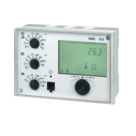
- Page 1 Automation System TROVIS 5500 Heating and District Heating Controller TROVIS 5575 Mounting and Operating Instructions EB 5575 EN Firmware version 1.6x ® Edition January 2007 Electronics from SAMSON...
- Page 2 Moreover, we do not guarantee that the buyer can use the product for an intended purpose. SAMSON rejects any liability for claims by the buyer, especially claims for compensation including lost profits or any other financial loss, except the damage was caused intentionally or by gross negligence.
-
Page 3: Table Of Contents
Contents Table of contents Operation ....... 7 Operating elements......7 1.1.1 Rotary pushbutton and changeover key . - Page 4 Contents Flash adaptation ......60 5.8.1 Flash adaptation without outdoor sensor (room temperature dependent) . 61 Adaptation .
- Page 5 Contents 7.12 Feeder pump operation ......88 7.13 Locking manual level ......88 7.14 Locking the rotary switches .
- Page 6 Controller versions Controller versions The TROVIS 5575 Heating Controller is available in various versions. The type designation registered on the nameplate of the controller indicates the controller version: Type designation (nameplate) Version TROVIS 5575-000x Standard controller with illuminated display background and with...
-
Page 7: Operation
Operation Operation The controller is ready for use with the temperatures and operating schedules preset by the manufacturer. On start-up, the current time and date need to be set at the controller (–> section 1.5). Operating elements The operating controls are located in the front panel of the controller and protected by a Plexiglas door. -
Page 8: Rotary Switches
Operation 1.1.2 Rotary switches Use the three rotary switches to adjust the desired operating mode (icons on the left) and the relevant parameters (icons on the right). The top and middle switches are assigned to the heating circuits (see page 121). The rotary switch in the middle is not used in systems without a second heating circuit. -
Page 9: Operating Modes
Operation Rotary switch to adjust the parameters of the DHW circuit Set point for DHW temperature Times-of-use for DHW heating Times-of-use for DHW circulation pump Party mode Note! If several rotary switches are set to “Parameter“ (right side), blinks on the display. The controller cannot be operated. -
Page 10: Display
* UP1, UP2, SLP, UP5, bA9 indicate possible choices for pump selection in manual operating mode. Fig. 1 · Icons The controller status can be displayed in operating level (–> section 1.4). TROVIS 5575-000x and TROVIS 5575-001x: An illuminated display indicates that the controller is being operated or a fault exists. TROVIS 5575-002x:... -
Page 11: Displaying Data
Operation Displaying data The time, date, public holidays and vacation periods as well as the temperatures of con- nected sensors and their set points can be retrieved and displayed with the help of the rotary pushbutton. Note! Data can also be viewed in manual operating mode To do so, select Info, confirm and proceed as described below. -
Page 12: Setting The Controller Time
Operation Setting the controller time The current time and date need to be set immediately after start-up and after a power failure of more than 24 hours has occurred. This is the case when the time blinks on the display. Proceed as follows: Turn the top rotary switch to position “Controller... -
Page 13: Setting The Times-Of-Use
Operation Setting the times-of-use Three times-of-use can be set for each day of the week. If only one time-of-use is required, the start and stop times of the second time-of-use must be adjusted to identical values. In this case, the third time-of-use is not displayed. If only two times-of-use are required, the start and stop times of the third time-of-use must be adjusted to identical values. - Page 14 Operation Turn appropriate rotary switch to position Proceed as follows: “Times-of-use”. Display shows: 1–7 0 1 2 3 4 5 6 7 8 9 10 11 12 13 14 15 16 17 18 19 20 21 22 23 24 Select period/day for which the times-of-use are to be valid: 1–7 = every day, 1 = Monday, 2 = Tuesday, ..., 7 = Sunday...
-
Page 15: Setting Party Mode
Operation Setting party mode Using the Party mode function, the controller continues or activates rated operation of the controller during the time when the party timer is active, regardless of the adjusted times-of-use. The party timer begins when the rotary switch has been returned to operating mode “Automatic“. -
Page 16: Activating Extended Operating Level
Operation Activating extended operating level After the key number 1999 has been adjusted, the following information can be viewed and edited after the data points listed in section 1.4 have been displayed: Flow rate Heat capacity Public holidays “ “ (editable) Vacation periods “... -
Page 17: Setting Public Holidays
Operation 1.8.1 Setting public holidays On public holidays, the times-of-use specified for Sunday apply. A maximum of 20 public holidays may be entered. Parameter Level / Range of values Public holidays – Extended operating level / 01.01 (1 Jan) to 31.12 (31 Dec) Proceed as follows: In extended operating mode, select “Public holidays“. -
Page 18: Setting Vacation Periods
Operation 1.8.2 Setting vacation periods During vacation periods, the controller constantly remains in reduced operating mode. A maximum of 10 vacation periods can be entered. Each vacation period can be assigned separately to the heating circuits Rk1 to Rk2 and/or to the DHW circuit. Level / Range of values Parameter Vacation period (START, STOP) - Page 19 Operation Exit data point “Vacation periods“. Note! Vacation periods can also be adjusted in parameter level PA5 (–> section 2.3). Deleting vacation periods: Under “Vacation periods“, select the start date of the period you wish to delete. Confirm selection. Select – – – – . Delete vacation period.
-
Page 20: Presetting Room And Dhw Temperature Set Points
Operation Presetting room and DHW temperature set points For the heating circuits, the desired room temperatures during the day ( Day set point ) and during the night ( Night set point ) can be preset. In the DHW circuit, the temperature you wish the DHW to be heated to can be adjusted. The temperature set points for the different control circuits are adjusted at the rotary switches one after the other: Desired temperature set point... - Page 21 PA2/CO2: Heating circuit Rk2 ( PA4/CO4: DHW heating PA5/CO5: System-wide CO7: Device bus Anl: System code number Fig. 2 · Level structure of TROVIS 5575 TROVIS 5575-002x: Version without device bus: Settings in CO7 level do not apply. EB 5575 EN...
-
Page 22: Start-Up
Setting the system code number 21 different hydraulic schemes are available in the TROVIS 5575-000x standard version and in the TROVIS 5575-002x version. The TROVIS 5575-001x version has two additional hydraulic schemes. Each system configuration is represented by a system code number. The different schematics are dealt with in section 4. -
Page 23: Activating And Deactivating Functions
Start-up Activating and deactivating functions A function is activated via the associated function block. The numbers 0 to 24 in the top row of the display represent the respective function block numbers. When a configuration level is opened, the activated function blocks are indicated by a black square on the right-hand side below the function block number. - Page 24 Start-up Deactivate the function block. Display shows: F__ - 0 Confirm settings. If the function block is not closed, further function block parameters can be adjusted. Proceed as follows: Make the desired changes and confirm. If applicable, the next function block parameter is displayed. Confirm all parameters to exit the opened function block.
-
Page 25: Changing Parameters
Start-up Changing parameters Depending on the adjusted system code number and the activated functions, not all parame- ters listed in the parameter list in the Appendix (–> section 12.2) might be available. The parameters are grouped by topics: PA1: Heating circuit Rk1 ( PA2: Heating circuit Rk2 ( PA3: Not used PA4: DHW heating... -
Page 26: Calibrating The Sensors
Start-up Calibrating the sensors The connected sensors are calibrated in configuration level CO5. The following applies: CO5 -> F01 - 1 and CO5 -> F02 - 0: Pt 1000 (Pt 100) sensors (default setting) CO5 -> F01 - 0 and CO5 -> F02 - 0: PTC (Pt 100) sensors CO5 ->... -
Page 27: Resetting To Default Values
Start-up Return flow sensor RüF Storage sensor SF1 Storage sensor SF2 Storage sensor SF2 for solar circuit Flow sensor VF4 Display measured value. Measured value blinks. Correct measured value. Read the actual temperature directly from the thermometer at the point of measurement and enter this value as reference temperature. -
Page 28: Manual Operation
Manual operation Manual operation Switch to manual operating mode to configure all outputs (see wiring diagram in sec- tion 11). Manual operation for the different control circuits is adjusted at the rotary switches: Manual operation Rotary switch Position Heating circuit 1* Heating circuit 2* Middle DHW circuit*... -
Page 29: Systems
Systems Systems 21 (23 in TROVIS 5575-001x) different hydraulic schemes are available. The systems can be designed as primary or secondary systems. The fundamental hydraulic differences between a primary and a secondary system are illustrated in Fig. 3. 1. A mixing valve replaces the heat exchanger in the heating/DHW circuit 2. - Page 30 Systems Boiler systems: Single-stage boiler systems can be configured to include any system whose heating circuits and DHW circuit include just one heat exchanger. These systems are Anl 1.0, 1.5, 1.6, 2.x, 3.0, 4.0 and 4.1. The boiler can be controlled by an on/off output (CO1 -> F12 - 0). Boiler single-stage RüF1...
- Page 31 Systems System Anl 1.0 (all versions of TROVIS 5575-00xx) RüF1 RüF1 Default settings CO1 -> F01 - 0 (without RF1) CO1 -> F02 - 1 (with AF1) CO1 -> F03 - 1 (with RüF1) EB 5575 EN...
- Page 32 Systems Systems Anl 1.1 to 1.3 (all versions of TROVIS 5575-00xx) heating Unfold back cover! RüF1 RF1 System Anl 1.1 Anl 1.2 Anl 1.3 Type of DHW heating Type 1 Type 2 Type 3 XX = Integration of flow sensor VF4...
- Page 33 Systems System Anl 1.5 (all versions of TROVIS 5575-00xx) RüF1 Default setting CO1 -> F03 - 1 (with RüF1) CO4 -> F01 - 1 (with SF1) CO4 -> F02 - 0 (without SF2) EB 5575 EN...
- Page 34 Systems System Anl 1.6 (all versions of TROVIS 5575-00xx) RüF1 System Anl 1.6 Anl 1.6 With pre-control Without pre-control Integration of VF4, UP1 Possible Not possible ZP integration with CO4 -> Possible Possible F10 - 1 (broken line, see cover) –...
- Page 35 Systems System Anl 1.9 (all versions of TROVIS 5575-00xx) Default setting CO4 -> F01 - 0 (without SF1) CO4 -> F03 - 0 (without RüF2) CO4 -> F04 - 0 (without water flowmeter connected to terminals 03/13) EB 5575 EN...
- Page 36 Systems System Anl 2.0 (all versions of TROVIS 5575-00xx) RüF1 Default setting CO1 -> F01 - 0 (without RF1) CO1 -> F02 - 1 (with AF1) CO1 -> F03 - 1 (with RüF1) CO4 -> F01 - 1 (with SF1) CO4 ->...
- Page 37 Systems Systems Anl 2.1 to 2.3 (all versions of TROVIS 5575-00xx) heating Unfold back cover! RüF1 System Anl 2.1 Anl 2.2 Anl 2.3 Type of DHW heating Type 1 Type 2 Type 3 XX = Integration of flow sensor VF4...
- Page 38 Systems System Anl 3.0 (all versions of TROVIS 5575-00xx) RüF2 RüF1 Default setting CO1 -> F02 - 1 (with AF1) CO1 -> F03 - 1 (with RüF1) CO2 -> F01 - 0 (without RF2) CO2 -> F03 - 0 (without RüF2)
- Page 39 Systems System Anl 3.1 (TROVIS 5575-001x version only) RüF2 RüF1 Default setting CO1 -> F02 - 1 (with AF1) CO1 -> F03 - 1 (with RüF1) CO2 -> F01 - 0 (without RF2) CO2 -> F03 - 0 (without RüF2) CO4 ->...
- Page 40 Systems System Anl 3.2 (TROVIS 5575-001x version only) RüF2 RüF1 Default setting CO1 -> F02 - 1 (with AF1) CO1 -> F03 - 1 (with RüF1) CO2 -> F01 - 0 (without RF2) CO2 -> F03 - 0 (without RüF2) CO4 ->...
- Page 41 Systems System Anl 3.5 (all versions of TROVIS 5575-00xx) RK1/Y1 RüF1 Control and UP1 are only active during the processing of an external Note demand. Default setting CO1 -> F03 - 1 (with RüF1) EB 5575 EN...
- Page 42 Systems System Anl 4.0 (all versions of TROVIS 5575-00xx) RüF2 RüF1 Default setting CO1 -> F01 - 0 (without RF1) CO1 -> F02 - 1 (with AF1) CO1 -> F03 - 1 (with RüF1) CO2 -> F01 - 0 (without RF2) CO2 ->...
- Page 43 Systems System Anl 4.1 (all versions of TROVIS 5575-00xx) RüF2 RüF1 ZP* SF1 The circulation pump ZP can only be controlled with the * Note TROVIS 5575-001x version. Default setting CO1 -> F01 - 0 (without RF1) CO1 -> F02 - 1 (with AF1) CO1 ->...
- Page 44 Systems System Anl 4.5 (all versions of TROVIS 5575-00xx) RüF2 RüF1 The circulation pump ZP can only be controlled with the * Note TROVIS 5575-001x version. Default setting CO1 -> F01 - 0 (without RF1) CO1 -> F02 - 1 (with AF1) CO1 ->...
- Page 45 Systems System Anl 10.0 (all versions of TROVIS 5575-00xx) RüF2 RüF1 Default setting CO1 -> F01 - 0 (without RF1) CO1 -> F02 - 1 (with AF1) CO1 -> F03 - 1 (with RüF1) CO2 -> F01 - 0 (without RF2) CO2 ->...
- Page 46 Systems System Anl 11.0 (all versions of TROVIS 5575-00xx) RK1 RK2 RüF1 RüF2 VF1 UP1 Default setting CO1 -> F01 - 0 (without RF1) CO1 -> F02 - 1 (with AF1) CO1 -> F03 - 1 (with RüF1) CO4 -> F03 - 0 (without RüF2)
- Page 47 Systems System Anl 11.1 (all versions of TROVIS 5575-00xx) RüF2 VF2 UP1 RK1 RüF1 RF1 Default setting CO1 -> F01 - 0 (without RF1) CO1 -> F02 - 1 (with AF1) CO1 -> F03 - 1 (with RüF1) CO4 -> F01 - 1 (with SF1) CO4 ->...
- Page 48 Systems System Anl 11.2 (all versions of TROVIS 5575-00xx) RüF1 RüF2 Default setting CO1 -> F01 - 0 (without RF1) CO1 -> F02 - 1 (with AF1) CO1 -> F03 - 1 (with RüF1) CO4 -> F01 - 1 (with SF1) CO4 ->...
- Page 49 Systems System Anl 11.9 (all versions of TROVIS 5575-00xx) Default setting CO1 -> F01 - 0 (without RF1) CO1 -> F02 - 1 (with AF1) CO1 -> F03 - 1 (with RüF1) CO4 -> F01 - 0 (without SF1) CO4 -> F03 - 0 (without RüF2)
-
Page 50: Functions Of The Heating Circuit
Functions of the heating circuit Functions of the heating circuit Which controller functions are available depends on the selected system code number (Anl). Weather-compensated control When weather-compensated control is used, the flow temperature is adjusted depending on the outdoor temperature. The heating characteristic in the controller defines the flow temper- ature set point as a function of the outdoor temperature (–>... -
Page 51: Gradient Characteristic
Functions of the heating circuit TROVIS 5575-000x and TROVIS 5575-001x: The outdoor temperature is alternatively received over the device bus when the following configurations are made: CO7 -> F01- 1 and CO7 -> F07 - 1 An outdoor temperature input independent from AF1 can be sent over the device bus for a second heating circuit following configurations are made: CO2 ->... -
Page 52: 4-Point Characteristic
Functions of the heating circuit Configuration Functions 4-point characteristic CO1, 2 -> F11 - 0 Rotary switch / Range of values Parameters Day set point 20 °C Top, middle / 0 to 40 °C Night set point 15 °C Top, middle / 0 to 40 °C Parameter level / Range of values Parameters Gradient, flow... -
Page 53: Fixed Set Point Control
Functions of the heating circuit Note! The parameters Day set point and Night set point s are no longer available when the 4-point characteristic has been selected, provided no additional functions (e.g. Optimization, Flash adaptation) have been selected. Functions Configuration 4-point characteristic CO1, 2 ->... -
Page 54: Underfloor Heating/Drying Of Jointless Floors
Functions of the heating circuit Configuration Functions Outdoor sensor AF1 CO1 -> F02 - 0 Rotary switch / Range of values Parameter Day set point 50 °C Top, middle / Min. to max. flow temperature Night set point 30 °C Top, middle / Min. - Page 55 Functions of the heating circuit The drying function is activated by changing the setting STOP to START after Temperature re- duction . The course of the drying process can be monitored in the information level over the icon of flow temperature display ( ) of the associated heating circuit: Temperature build-up phase Temperature maintaining phase...
-
Page 56: Deactivation Depending On Outdoor Temperature
Functions of the heating circuit Deactivation depending on outdoor temperature 5.4.1 OT deactivation value in rated operation If the outdoor temperature exceeds the limit entered in OT deactivation value in rated opera- tion , the heating circuit concerned is put out of service immediately. The valve is closed and the pump is switched off after t = 2 x valve transit time. -
Page 57: Summer Mode
Functions of the heating circuit 5.4.4 Summer mode Summer mode is activated depending on the mean daytime temperature (measured between 7.00h and 22.00h) during the desired period. If the mean daytime temperature exceeds the OT limit value in summer mode on n successive days, summer mode is activated on the following day. -
Page 58: Remote Operation
Terminal 12 Terminal 12 Terminal 3 Terminal 9 Terminal 10 Fig. 7 · Wiring plan for Type 5244/5257-5 Room Panels to TROVIS 5575 for Rk1 or Rk2 Configuration Function Rooms sensors RF1/2 CO1, 2 -> F01 - 1 EB 5575 EN... -
Page 59: Optimization
Functions of the heating circuit TROVIS 5575-000x and TROVIS 5575-001x: Alternatively, the TROVIS 5570 Room Panel can be connected when the following configu- rations are made: CO7 -> F01 -1 and CO7 -> F03 - 1 and CO7 -> F04 - 1 (see section 7.11.5) The Day set point set by the rotary switch remains unaffected by set point corrections per- formed at the room panel. -
Page 60: Flash Adaptation
Functions of the heating circuit Configuration Functions Room sensors RF1/2 CO1, 2 -> F01 - 1 Outdoor sensors AF1 CO1 -> F02 - 1 Optimization CO1, 2 -> F07 - 1 Parameters Rotary switch / Range of values Day set point 20 °C Top, middle / 0 to 40 °C Night set point... -
Page 61: Flash Adaptation Without Outdoor Sensor (Room Temperature Dependent)
Functions of the heating circuit 5.8.1 Flash adaptation without outdoor sensor (room temperature dependent) The flow temperature control starts with Flow day set point in rated operation or with Flow night set point in reduced operation as no set points calculated using characteristics exist without an outdoor sensor. -
Page 62: Adaptation
Functions of the heating circuit Adaptation The controller is capable of automatically adapting the heating characteristic to the building characteristics, provided a gradient characteristic has been set (CO1, 2 -> F11 - 0). The ref- erence room, where the room sensor is located, represents the entire building and is moni- tored to ensure that the room set point ( Day set point) is maintained. -
Page 63: Functions Of The Dhw Circuit
Functions of the DHW circuit Functions of the DHW circuit DHW heating in the storage tank system Start storage tank charging Storage tank charging pump Storage sensor 1 Circulation pump Hot water Cold water Fig. 8 · Schematics of a storage tank system The controller begins charging the storage tank when the water temperature measured at sensor SF1 falls below the DHW temperature set point by 0.1 °C. - Page 64 Functions of the DHW circuit Time-controlled switchover of storage tank sensors By configuring a second storage tank sensor SF2 over the function block CO4 -> F19 -1, it is possible to determine that the storage tank sensor SF1 is used for day mode in the DHW cir- cuit and that the storage tank sensor SF2 is used for night mode.
-
Page 65: Dhw Circuit Additionally Controlled By A Globe Valve
Functions of the DHW circuit Parameter level / Range of values Parameters Lag of storage tank charging pump PA4 / 0 to 10.0 Sustained DHW temperature 40 °C PA4 / 20 to 90 °C Parameters serve as limitation of the adjustment range for the DHW temperature to be set at the rotary switch ** Deactivation value T = DHW temperature + hysteresis *** Charging temperature T = DHW temperature + charging temperature boost... -
Page 66: Dhw Heating In The Storage Tank Charging System
Functions of the DHW circuit DHW heating in the storage tank charging system Start storage tank charging Exchanger charging pump Flow sensor Storage tank charging pump Storage sensor 1 Storage sensor 2 Circulation pump Hot water Cold water Fig. 10 · Schematics of a storage tank charging system The controller begins charging the storage tank when the water temperature measured at sensor SF1 falls below the DHW temperature set point by 0.1 °C. - Page 67 Functions of the DHW circuit Note! The set point in the heat exchanger circuit which is valid at the end of the charging cycle will be used again at the beginning of the next cycle. If times-of-times have been set for DHW heating, the Set point DHW temperature adjusted at the rotary switch is applied during these times-of-use.
-
Page 68: Dhw Heating In Instantaneous Heating System
System-wide functions Parameter level / Range of values Parameters Hysteresis** 5 °C PA4 / 0 to 30 °C Charging temperature boost*** 10 °C PA4 / 0 to 50 °C Max. charging temperature 80 °C PA4 / 20 to 130 °C (only with VF4) Lag of storage tank charging pump PA4 / 0 to 10.0 Sustained DHW temperature... -
Page 69: Dhw Heating With Solar System
Appendix Parameter level / Range of values Parameters Min. DHW temperature 40 °C PA4 / 5 to 90 °C Max. DHW temperature 60 °C PA4 / 5 to 90 °C DHW heating with solar system The systems Anl 1.3 and 2.3 include a solar system for DHW heating. In these systems, the difference between the temperatures measured at storage sensor SF2 and the sensor at the solar collector VF3 is determined. -
Page 70: Parallel Pump Operation
Appendix Parallel pump operation This function is only available in systems Anl 2.1 to 2.3, 4.1 and 4.5. With the setting CO4 -> F06 - 1, the circulation pump UP1 remains switched on during DHW heating unless certain operating situations occur. These situations include, for example, those when the cur- rent flow temperature demand of the pump circuit is lower than the adjusted Flow limit tem- perature for parallel pump operation . -
Page 71: Reverse Control
Appendix 6.8.1 Reverse control In all systems with DHW heating and at least one heating circuit with control valve, DHW heating can be given priority by applying reverse control. With the setting CO4 -> F08 - 1, the temperature at the sensor VFx in the DHW circuit can be monitored. In systems without the sensor VFx in the DHW circuit (e.g. -
Page 72: Thermal Disinfection Of The Dhw Storage Tank
Appendix T = DHW temperature + hysteresis . The forced charging of the storage tank does not take place when the DHW circuit is not used at the beginning of the time-of-use set for the heating circuit(s). Note! This function is not available when a storage tank thermostat is used. 6.10 Thermal disinfection of the DHW storage tank In all systems with DHW heating, the DHW storage tank is thermally disinfected on a se- lected Day of the week or every day. - Page 73 Appendix Note! This function is not available when a storage tank thermostat is used. Controllers that are linked over a device bus are subjected to return flow temperature limita- tion in the primary control circuit even during the thermal disinfection in a secondary control- ler.
-
Page 74: System-Wide Functions
System-wide functions System-wide functions Automatic summer time/winter time changeover The clock is automatically adjusted on the last Sunday in March at 2.00h and on the last Sunday in October at 3.00h. Configuration Function CO5 -> F08 - 1 Summer time/winter time changeover Frost protection Frost protection measures become effective whenever the outdoor temperature falls below the Frost protection limit. -
Page 75: Forced Operation Of The Pumps
System-wide functions Forced operation of the pumps When the heating circuit pumps have not been activated for 24 hours, forced operation of the pumps is started between 12.02h and 12.03h. This is done to avoid that the pumps get stuck when they are not operated for a longer period of time. In the DHW circuit, the circula- tion pump is operated between 12.04h and 12.05h, the other pumps between 12.05h and 12.06h. -
Page 76: Condensate Accumulation Control
System-wide functions Configuration Function Return flow sensors RüF1/2 CO1, 2, 4 -> F03 - 1 Limiting factor/ 0.1 to 10.0 Return flow temperature CO5 -> F16 limitation with P algorithm Parameters Parameter level/Range of values Gradient, return flow PA1, 2 / 0.2 to 3.2 Level, return flow 0.0 °C PA1, 2 / –30 to 30 °C... -
Page 77: Three-Step Control
System-wide functions Three-step control The flow temperature can be controlled using a PI algorithm. The valve reacts to pulses that the controller emits upon an existing system deviation. The length of the first pulse, in particu- lar, depends on the extent of the system deviation and the selected Proportional gain K (the pulse length increases as K increases). -
Page 78: Processing Of External Demand In Rk1
System-wide functions It remains active, however, in any case for processing of external demand. The control circuit can be released via the binary input when the binary input is either open (bE = 0) or closed (bE = 1). Note! In systems with supplementary heating circuit without a valve (Anl 2.x, 4.x), BE1 only influen- ces the operation of this heating circuit. - Page 79 System-wide functions Processing of external demand, binary Regardless of the operating mode set for control circuit Rk1 – except manual mode –, the flow temperature specified as Set point for binary demand processing is adjusted in control circuit Rk1 when the binary input (terminals 03/12) is either open (bE = 0) or closed (bE = 1).
-
Page 80: Flow Rate/Heat Capacity Limitation In Rk1
System-wide functions 7.10 Flow rate/heat capacity limitation in Rk1 Flow rate/heat capacity limitation can be implemented based on a pulse or standardized signal of 0/4 to 20 mA provided by the heat meter. This only applies in plants without SF2, RF2 and without processing of an external demand 0 to 10 V. -
Page 81: Limitation Using 0/4 To 20 Ma Signal
System-wide functions Example to determine the limit value: If a capacity of 30 kW is to be limited, the following limit value must be set for a heat meter with an output of one pulse per kilowatt-hour: 30 kW 30 pulse / h 1 kWh / pulse Note! If CO5 ->... -
Page 82: Creep Feed Rate Limitation Over Binary Input
System-wide functions Configuration Functions Flow rate limitation (capacity limi- CO5 -> F10 - 0 tation) in Rk1 with pulses at input Flow rate limitation in Rk1 using CO5 -> F11 - 1 0/4 to 20 mA at input WMZ Lower measuring range value / 0, 4 mA Upper meas. -
Page 83: Device Bus
Using the device bus, it is possible to connect up to 32 device (from Series 55xx). For con- nection, the TROVIS 5575 Controller is, above all, equipped with the terminals 14/15. No attention must be paid to the polarity of the device bus wiring. -
Page 84: Requesting And Processing An External Demand
System-wide functions Requesting and processing an external demand (–> page 84) Sending and receiving outdoor temperatures (–> page 85) Synchronizing the clock (–> page 86) Priority over all controllers (–> page 86) Connecting a TROVIS 5570 Room Panel (–> page 87) Display error alarms issued by the device bus (–>... -
Page 85: Sending And Receiving Outdoor Temperatures
System-wide functions Secondary controller: Functions Configuration Device bus CO7 -> F01 - 1 Device bus address Send flow set point Rk1 CO7 -> F10 - 1* Send flow set point Rk2 CO7 -> F11 - 1* Send flow set point DHW CO7 ->... -
Page 86: Synchronizing The Clock
System-wide functions Configuration Functions Receive value AF1 CO7 -> F07 - 1 Register no. / 1 to 4 Receive value AF2 (receive an outdoor temp. CO7 -> F09 - 1 independent of Rk1) Register no. / 2 to 4 Note! The register no. -
Page 87: Connecting A Trovis 5570 Room Panel
*Register no. / 5 to 64 7.11.5 Connecting a TROVIS 5570 Room Panel A TROVIS 5570 Room Panel (accessory) can be connected to the TROVIS 5575 Controller to measure the room temperature and for remote operation of a heating circuit. The room panel enables direct access to the operating mode and controller time settings as well as to all relevant parameters of a heating circuit. -
Page 88: Feeder Pump Operation
System-wide functions 7.12 Feeder pump operation In system Anl 3.0, the feeder pump UP1 only starts to operate in the default setting when a flow temperature demand of a secondary controller exists. If CO7 -> F14 - 1 is configured in the primary controller in addition to CO7 -> F15 - 1, the function is also active when the controller’s own secondary circuit requires heat. -
Page 89: Setting A Customized Key Number
System-wide functions 7.15 Setting a customized key number To avoid that unauthorized personnel modify functions and parameters of the controller, the default key number can be replaced with an individual key number. Choose your custom key number between 0100 and 1900. Proceed as follows: Switch to configuration and parameter level. -
Page 90: Operational Faults
In addition, the display is illuminated for 1 second in intervals of 10 seconds when a fault persists. TROVIS 5575-000x and TROVIS 5575-001x: The display is illuminated approximately every 10 seconds for one second when opera- tional faults occur. -
Page 91: Temperature Monitoring
Operational faults Outdoor sensors AF1: When the outdoor sensor fails, the controller adjusts a flow tem- perature set point of 50 °C or the Max. flow temperature when the Max. flow tempera- ture (adjusted under PA1, 2) is smaller than 50 °C. Flow sensor(s) heating circuit(s): When the flow sensors in the heating circuits are defec- tive, the associated valve moves to 30 % travel. -
Page 92: Memory Module
RJ45 connector integrated into the front panel. Once the module has been connected, “75 SP“ is displayed. If the memory module already contains data from a different TROVIS 5575 Controller, turn the rotary pushbutton until “SP 75" is displayed Pressing the rotary pushbutton to confirm “75 SP“... -
Page 93: Installation
Installation Installation Dimensions in mm (W x H x D) TROVIS 5575-000x and TROVIS 5575-001x Controller with standard housing base: 144 x 98 x 60 TROVIS 5575-002x The controller can be fitted with a standard housing base or a high base. - Page 94 Installation Top hat rail mounting 1. Fasten the spring-loaded hook (4) at the bottom of the top hat rail (3). 2. Slightly push the controller upwards and pull the upper hook (5) over the top hat rail. 3. Remove both screws (1). 4.
- Page 95 Installation Panel mounting Housing base Controller housing Wall mounting Top hat rail mounting Fig. 12 · Installation EB 5575 EN...
-
Page 96: Electrical Connection
Electrical connection Electrical connection Caution! For electrical installation, you are required to observe the relevant electrotechnical regula- tions of the country of use as well as the regulations of the local power suppliers. Make sure all electrical connections are installed by trained and experienced personnel! Notes on installing the electrical connections Install the 230 V power supply lines and the signal lines separately! To increase noise im- munity, observe a minimum distance of 10 cm between the lines. - Page 97 Electrical connection Connecting the water flowmeter (order no. 1400-9246) A power supply unit and a 4.7 kΩ resistor are required for the water flowmeter to function. Water Flowmeter TROVIS 5575 Power supply unit 4.5 ... 24 V DC brown/ white...
- Page 98 Electrical connection EB 5575 EN...
- Page 99 Electrical connection EB 5575 EN...
- Page 100 Electrical connection EB 5575 EN...
- Page 101 Electrical connection EB 5575 EN...
-
Page 102: Appendix
Appendix Appendix 12.1 Function block lists CO1: Heating circuit Rk1 (not system Anl 1.9)* Comments Function block parameters/Range of values (default setting) F Function 01 Room sensor RF1 Not in Anl CO1 -> F01 - 1: Temperature display and input FG1 for 1.5, 1.6, Type 5244/5257-5 Room Panel active TROVIS 5570 Room Panel:... - Page 103 Appendix Comments F Function Function block parameters/Range of values (default setting) 11 4-point Not in Anl CO1 -> F11 - 1: 4-point characteristic, only with characteristic 1.5, 1.6, CO1 -> F08 - 0 CO1 -> F11 - 0: Gradient characteristic 12 Control type All* CO1 ->...
- Page 104 Appendix CO2: Heating circuit Rk2 (Systems Anl 3.0-3.4, 4.x and 10.0)* Comments F Function Function block parameters/Range of values (default setting) 01 Room sensor RF2 All* CO2 -> F01 - 1: Temperature display and input FG2 for Type 5244/5257-5 Room Panel active TROVIS 5570 Room Panel: CO2 ->...
- Page 105 Appendix Comments F Function Function block parameters/Range of values (default setting) 12 Control type All* CO2 -> F12 - 1: Three-step control three-step Function block parameters: (proportional gain) / 0.1 to 50.0 (2.0) (reset time) / 1 to 999 s (120 s) (derivative-action time) / 0 s;...
- Page 106 Appendix CO4: DHW circuit (Systems Anl 1.1–1.3, 1.5, 1.6, .19, 2.x, 3.1, 3.2, 4.1, 4.5, 11.x )* Comments F Function Function block parameters/Range of values (default setting) 01 Storage tank sensor CO4 -> F01 - 0 (not Anl 11.0): Storage tank thermostat, only with CO4 ->...
- Page 107 Appendix Comments F Function Function block parameters/Range of values (default setting) 08 Priority through 1.1–1.3, CO4 -> F08 - 1 Only withCO4 -> F09 - 0 reverse control 3.1, 3.2, Function block parameters: 4.1, 4.5, Activate priority in case of deviation / 11.x 2 to 10 min (2 min) Correction factor / 0.1 to 10.0 (1.0)
- Page 108 Appendix Comments F Function Function block parameters/Range of values (default setting) 14 Thermal All* CO4 -> F14 - 1 only with CO4 -> F01 - 1 disinfection Function block parameters: Day of the week/ 1, 2, …, 7, 1–7 (3) Start time / 00:00 h to 23:45 h (00:00) Stop time / 00:00 h to 23:45 h (04:00) Disinfection temperature / 60 to 90 °C (70 °C)
- Page 109 Appendix CO5: System-wide functions (all systems) If CO5 -> F00 - 1 is indicated, access to the return flow, flow rate and heat capacity settings are locked. Comments F Function Function block parameters/Range of values (default setting) 01 Sensor initialization CO5 ->...
- Page 110 Appendix Comments F Function Function block parameters/Range of values (default setting) 10 Flow rate limitation Not in Anl CO5 -> F10 - 1 only with CO5 -> F11 - 0 (capacity limitation) 1.9, 10.0; Input “WMZ/Bed“ (terminals 03/13) in Rk1 with pulses Function block parameters: not in pulse...
- Page 111 Appendix Comments F Function Function block parameters/Range of values (default setting) 22 Locking the rotary CO5 -> F22 - 1: All rotary switches are locked switches 23 Test mode Only for internal use! *Not in systems Anl 1.0, 1.5, 1.6, 3.0, 3.5, 4.0, 11.x F Function block number, WE Default setting, Anl System code number EB 5575 EN...
- Page 112 Appendix CO7: Device bus (all systems; F02, F03, … only with CO7 -> F01 -1) Settings in CO7 level do not apply for TROVIS 5575-002x version. Comment F Function Function block parameters/Range of values (default setting) 01 Device bus CO7 -> F01 - 1: Device bus active...
- Page 113 Appendix Comment F Function Function block parameters/Range of values (default setting) 12 Reserved 13 Send flow set point CO7 -> F13 - 1: In level PA4, the Charging temperature boost parameter is generated Function block parameter: Register no. / 5 to 64 (5) 14 Send maximum CO7 ->...
-
Page 114: Parameter Lists
Appendix 12.2 Parameter lists PA1 ( ): Parameter level Rk1 PA2 ( ): Parameter level Heating circuit Rk 2 Parameter designation Display Range of values (default setting) 0 1 2 3 4 5 6 7 8 9 10 11 12 13 14 15 16 17 18 19 20 21 22 23 24 Gradient, flow 0.2 to 3.2 (1.8) (with CO1, 2 ->... - Page 115 Appendix Parameter designation Display Range of values (default setting) 0 1 2 3 4 5 6 7 8 9 10 11 12 13 14 15 16 17 18 19 20 21 22 23 24 4-point characteristic Press rotary pushbutton to adjust the parameters outdoor temperature, flow temperature, reduced flow temperature and...
- Page 116 Appendix Parameter designation Display Range of values (default setting) 0 1 2 3 4 5 6 7 8 9 10 11 12 13 14 15 16 17 18 19 20 21 22 23 24 OT deactivation value rated operation ˚C 0 to 50 °C (22 °C) STOP 0 1 2 3 4 5 6 7 8 9 10 11 12 13 14 15 16 17 18 19 20 21 22 23 24...
- Page 117 Appendix Parameter designation Display Range of values (default setting) 0 1 2 3 4 5 6 7 8 9 10 11 12 13 14 15 16 17 18 19 20 21 22 23 24 Return flow temperature foot ˚C 5 to 90 °C (65 °C) 0 1 2 3 4 5 6 7 8 9 10 11 12 13 14 15 16 17 18 19 20 21 22 23 24 Max.
- Page 118 Appendix PA4: Parameters DHW heating (Systems Anl 1.1 to 1.3, 1.5, 1.6, 1.9, 2.x, 4.1, 4.5 and 11.x) Parameter designation Range of values (default setting) Display 0 1 2 3 4 5 6 7 8 9 10 11 12 13 14 15 16 17 18 19 20 21 22 23 24 Min.
- Page 119 Appendix Parameter designation Display Range of values (default setting) 0 1 2 3 4 5 6 7 8 9 10 11 12 13 14 15 16 17 18 19 20 21 22 23 24 Max. charging temperature ˚C 20 to 130 °C (80 °C) Lag of storage tank charging pump 0 1 2 3 4 5 6 7 8 9 1 0 11 12 13 14 15 16 17 18 19 20 21 22 23 24 0 to 10.0 (0.5)
- Page 120 Appendix Parameter designation Display Range of values (default setting) 0 1 2 3 4 5 6 7 8 9 10 11 12 13 14 15 16 17 18 19 20 21 22 23 24 Solar pump OFF ˚C 0 to 30 °C (3 °C) STOP 0 1 2 3 4 5 6 7 8 9 10 11 12 13 14 15 16 17 18 19 20 21 22 23 24 Max.
-
Page 121: Assignment Of The Rotary Switches
Appendix 12.3 Assignment of the rotary switches System Anl Top rotary switch Middle rotary switch Bottom rotary switch Heating circuit Rk1 – – 1.1 to 1.3 Heating circuit Rk1 – DHW heating Primary heat exchanger 1.5, 1.6 – DHW heating circuit Rk1 –... -
Page 122: Sensor Resistance Tables
Appendix 12.4 Sensor resistance tables Resistance values with PTC resistors Type 5224 Outdoor Temperature Sensors, Type 5264 and Type 5265 Flow and Return Flow Temperature Sensors, Type 5264 Storage Tank Temperature Sensors –20 –10 °C Ω 694 757 825 896 971 1010 1050 1132 1219 1309 1402 1500 1601 1706 1815 1925 °C 10 Type 5244 Room Panel Ω... -
Page 123: Technical Data
Appendix 12.5 Technical data Inputs 8 inputs for temperature sensor Pt 1000/Pt 100, PTC/Pt 100, NTC/Pt 100 or Ni 1000/Pt 100 and 2 binary inputs, Input terminal 03 alternatively for flow rate signal from heat meters or demand signal from supplementary control circuits, 4(0) to 20 mA with 50 Ω... -
Page 124: Customer Data
Appendix 12.6 Customer data Station Operator Responsible SAMSON office System code number Function block settings in the configuration levels CO 1 CO 2 CO 4 CO 5 CO 7 EB 5575 EN... - Page 125 Appendix Parameters in level 1 and level 2 (control circuit 1 and 2) Parameters (PA1 and PA2) Level 1 Level 2 Range of values Gradient, flow 0.2 to 3.2 Level, flow –30 to 30 °C Min. flow temperature 5 to 130 °C Max.
- Page 126 Appendix Function block parameters (CO1 and CO2) Level 2 Range of values Limiting factor (F03 - 1) 0.1 to 10.0 Temperature rise (F05 - 1) 1 to 10 °C/24 h Maximum temperature (F05 - 1) 25 to 60 °C Maintaining time of max. temp. (F05 - 1) 1 to 10 days Temperature reduction (F05 - 1) 0 to 10 °C/24 h...
- Page 127 Appendix Function block parameters (CO4) Limiting factor (F03 - 1) 0.1 to 10.0 Analysis to terminals 03/13 (F04 - 1) AnA, bin Stop parallel operation in case of deviation (F06 - 1) 0 to 10 min Flow limit temp. f. parallel pump operation (F06 - 1) 20 to 90 °C Activate priority in case of deviation (F08 - 1) 2 to 10 min...
- Page 128 Appendix Parameters in level 5 Parameter (PA5) Level 5 Range of values Vacation 01.01 to 31.12 Vacation period, Start 01.01 to 31.12 Vacation period, Stop Assignment to control circuit Rk1, Rk2, Rk4 Vacation period, Start 01.01 to 31.12 Vacation period, Stop Assignment to control circuit Rk1, Rk2, Rk4 Function block parameters (CO5)
- Page 129 Appendix Max. limit value (F13 - 1) 0.1 to 6500 kW Max. limit value heating (F13 - 1) 0.1 to 6500 kW Max. limit value DHW (F13 - 1) 0.1 to 6500 kW Limiting factor (F13 - 1) 0.1 to 10.0 Parameters in level 7 Function block parameters (CO7) Level 7...
- Page 130 Appendix Rotary switch settings Parameters Top rotary switch Range of values to 40 °C Day set point to 130 °C to 40 °C Night set point to 130 °C Times-of-use Start of first time-of-use 0:00 to 24:00 h End of first time-of-use 0:00 to 24:00 h Start of second time-of-use 0:00 to 24:00 h...
- Page 131 Appendix Parameter Bottom rotary switch Range of values DHW temperature 20 to 90 °C Times-of use DHW heating Start of first time-of-use 0:00 to 24:00 h End of first time-of-use 0:00 to 24:00 h Start of second time-of-use 0:00 to 24:00 h End of second time-of-use 0:00 to 24:00 h Start of third time-of-use...
-
Page 132: Index
Index Index Deactivation depending on outdoor 4-point characteristic ....52 temperature ..... . 56 Default settings. - Page 133 Index Gradient characteristic ....51 On/off control ....77 Operating elements .
-
Page 134: Key Number
Index Rotary pushbutton ....7 Rotary switch Technical data ....123 DHW circuit . - Page 135 EB 5575 EN...
- Page 136 Type 1 Type 2 SF2 ZP Type 3 Solar collector...
-
Page 137: Frequently Used Abbreviations
Frequently used abbreviations Outdoor sensor Terminal Exchanger charging System Cold water pump Binary output Outdoor temperature TWE Domestic hot water Binary input Parameter level Circulation pump Configuration level Room sensor Flow sensor DHW Domestic hot water Control circuit Default setting RüF Mounting and Return flow sensor... - Page 138 SAMSON AG · MESS- UND REGELTECHNIK Weismüllerstraße 3 · 60314 Frankfurt am Main · Germany Phone +49 69 4009-0 · Fax +49 69 4009-1507 EB 5575 EN Internet: http://www.samson.de...
Need help?
Do you have a question about the TROVIS 5575 and is the answer not in the manual?
Questions and answers