Samson Trovis 6400 Mounting And Operating Instructions
Automation system, process control stations
Hide thumbs
Also See for Trovis 6400:
- Mounting and operating instructions (38 pages) ,
- Mounting and operating instructions (46 pages) ,
- Mounting and operating instructions (91 pages)

Related Manuals for Samson Trovis 6400


Summary of Contents for Samson Trovis 6400
- Page 1 Automation System TROVIS 6400 Process Control Stations TROVIS 6412 and 6442 Edition July 2007 Mounting and Operating Instructions Firmware C 1.3 EB 6412 EN Firmware Si 1.4...
-
Page 3: Table Of Contents
Contents Notes on these mounting and operating instructions........5 1.1. Documentation ..................... 5 1.2. Abbreviations used in this manual..............5 Description....................6 2.1. Features ....................... 6 2.2. Versions ....................... 6 2.3. The process control station (overview)............. 7 2.4. Technical data ....................8 Installing the process control stations ............ - Page 4 6.10. level (code number for the PARAMETER level) ......44 6.11. level (code number for the CONFIGURATION level)....44 6.12. Ini level (resetting the process control station to its default values) ....45 6.13. AdP level (adaptation of the control parameters) ..........46 6.13.1. Single adaptation (adaptation during the start-up phase)........48 6.13.2.
-
Page 5: Notes On These Mounting And Operating Instructions
Notes on these mounting and operating instructions Documentation 1. Notes on these mounting and operating instructions 1.1.Documentation Two manuals constitute the documentation for the TROVIS 6412 and 6442 Process Control Stations: Mounting and Operating Instructions EB 6412 EN and Configuration Manual KH 6412 EN. -
Page 6: Description
Features Description 2.Description 2.1. Features The TROVIS 6412 and 6442 Process Control Stations are microprocessor-controlled devices used to automate industrial and process engineering plants. They are suitable not only for constructing simple control loops, but for solving complex control problems as well. The TROVIS 6412 and TROVIS 6442 Process Control Stations only differ from each other in their design (see section 2.2.). -
Page 7: The Process Control Station (Overview)
Description The process control station (overview) 2.3.The process control station (overview) Fig. 1 ⋅ Block diagram of the process control station... -
Page 8: Technical Data
Technical data Description 2.4. Technical data Inputs Input board Input 1 mA, V, Thermocouple potentiometer, Pt 100 in 2/3 or 4-wire (int./ext. transmitter circuit reference supply junction) Input 2 Pt 100 mA, V, mA, V input, in 2/3 transmitter transmitter supply or 4-wire supply circuit... - Page 9 Binary outputs 2; floating contacts; maximum 42 V AC (0.1 A AC); 42 V DC (0.05 A DC) Interfaces Serial RS-232 in conjunction w. SAMSON cable no. 1170-1141 interface Communications protocol TROVIS 6482 SAMSON Protocol on the Number of stations...
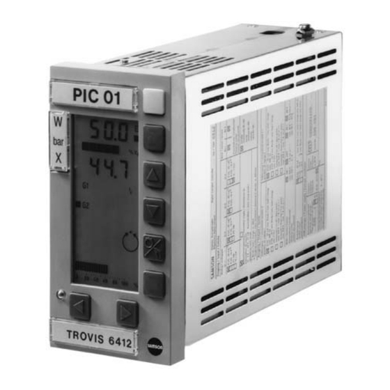
- Page 10 Technical data Description General specifications Displays Read-off angle Readable from all sides, high-contrast and lighted Liquid Crystal Display (LCD) Displays ⁄ -digit set point (reference variable) display and ⁄ -digit controlled variable display; bar graph displays for deviation (i.e. error) and output variable; LED displays for range exceeding, alarm messages when limits are exceeded, manual operation, faults etc.;...
-
Page 11: Installing The Process Control Stations
Installing the process control stations TROVIS 6412 (panel-mounting unit) 3. Installing the process control stations 3.1.TROVIS 6412 (panel-mounting unit) The TROVIS 6412 Process Control Station is designed for panel-mounting and has the front-frame dimensions 72 x 144 mm. Perform the following steps in order to mount the controller: +0.7 +1.0 Make a panel cut-out with the dimensions 68... -
Page 12: Trovis 6442 (Rack-Mounting Unit For 19Inch Racks)
TROVIS 6442 (rack-mounting unit for 19inch racks) Installing the process control stations 3.2. TROVIS 6442 (rack-mounting unit for 19inch racks) The TROVIS 6442 Process Control Station is a rack-mounting unit designed for mounting in 19inch racks. It has to be installed as follows: Push the control station along the guiding rails into the corresponding rack unit, making sure it does not become tilted. - Page 13 Installing the process control stations Opening the controller case Modify input (5, Fig. 5 ) or/ and interface board (6, Fig. 5 ): Unscrew the four screws (1, 2) and remove the two distance bolts (4). Carefully withdraw the input and/or interface board from the case. Modify the board as desired (see sections 4.1., 4.4.).
-
Page 14: Soldering Jumpers
Determining the input signals Soldering jumpers 4. Soldering jumpers ATTENTION! The soldering jumpers may only be modified by experienced personnel when the power to the process control station has been cut off! Several functions of the process control station are determined by means of soldering jumpers. Open the case as described in section 3.3. -
Page 15: Input Board 2 (Ib2)
Soldering jumpers Determining the input signals 4.1.2. Input board 2 (IB 2) Note: Select the desired input signal and close the related soldering jumpers listed in line 3 or the following ones of the table below (depending on type of signal selected)! Open all remaining jumpers associated with the corresponding input (line 2)! See Fig. -
Page 16: Input Board 3 (Ib3)
Determining the input signals Soldering jumpers 4.1.3. Input board 3 (IB 3) Note: Select the desired input signal and close the related soldering jumpers listed in line 3 or the following ones of the table below (depending on type of signal selected)! Open all remaining jumpers associated with the corresponding input (line 2)! See Fig. -
Page 17: Input Board 4 (Ib4)
Soldering jumpers Determining the input signals 4.1.4. Input board 4 (IB 4) Input board 4 is no longer available. Note: Select the desired input signal and close the related soldering jumpers listed in line 3 or the following ones of the table below (depending on type of signal selected)! Open all remaining jumpers associated with the corresponding input (line 2). - Page 18 Determining the input signals Soldering jumpers Input signal Input 1 Input 2 Input 3/4 (Ai 1) (Ai 2) (Ai 3/4) Jumpers: Jumpers: Jumpers: 10 to 19 20 to 26 41 to 47 Type S 0 to 700 °C 17 500 to 1200 °C 16 1000 to 1700 °C 15 0 to 1700 °C 14 Type L...
-
Page 19: Soldering Jumpers On The Logic Board
Soldering jumpers Soldering jumpers on the logic board 4.2.Soldering jumpers on the logic board See Fig. 5 for the location of the logic board Soldering jumper: X closed, 0 open SZ LB 1 LB 2 LB 3 Continuous 0(4) to 20 mA control output Y1 0(2) to 10 V Continuous... -
Page 20: Soldering Jumpers On The Interface Board
Soldering jumpers on the interface board Soldering jumpers 4.4. Soldering jumpers on the interface board See. Fig. 5 for the location of the interface board and Fig. 6 for the location of the soldering jumpers. Important! In the interface mode, the soldering jumpers LB1, LB2 and LB3 on the logic board must also be closed (see section 4.2., page 19). - Page 21 Soldering jumpers Soldering jumpers on the interface board Fig. 6 ⋅ Location of the soldering jumpers on the interface board...
-
Page 22: Electrical Connections
TROVIS 6412 (panel-mounting unit) Electrical connections 5. Electrical connections When making the electrical connections, note the VDE 0100 regulations and the regulations valid in the country where the control station is intended to be installed. Use shielded cables for the signal lines of the analog and binary inputs, which are installed outside the control cabinets, in order to avoid measuring errors or other interferences. - Page 23 Electrical connections TROVIS 6412 (panel-mounting unit) Ai 1 Ai 2 Ai 3 Ai 4 Inputs 11 12 13 14 15 16 17 18 18 19 20 21 23 24 25 Input board 1 – – – – (IB 1) – –...
-
Page 24: Trovis 6442 (Rack-Mounting Unit For 19Inch Racks)
TROVIS 6442 (rack-mounting unit for 19inch racks) Electrical connections 5.2. TROVIS 6442 (rack-mounting unit for 19inch racks) The device has two plug connectors, style F (DIN 41612). The signal lines are assigned to one of these two connectors, whereas the power supply lines are assigned to the other one, meaning these lines are installed separately (see Fig. - Page 25 Electrical connections TROVIS 6442 (rack-mounting unit for 19inch racks) Ai 1 Ai 3 Ai 4 Ai 2 Inputs 32 30 28 26 24 22 20 18 24 14 12 10 Input board 1 (IB 1) – – – – – –...
-
Page 26: Balancing The Line Resistance For The Connection Of Pt 100 Sensors
Balancing the line resistance for the connection of Pt 100 sensors Electrical connections 5.3. Balancing the line resistance for the connection of Pt 100 sensors When Pt 100 sensors are connected to the control station in a two-wire circuit, the line resistance is to be balanced to 10 Ω... - Page 27 Electrical connections Wiring technique with regard to electromagnetic compatibility Cu-flex. lead ≥ 1.5 mm Cu-flex. lead ≥ 2.5 mm Cu-flex. lead ≥ 10 mm Controller 1 Controller n Fig. 11 ⋅ Electrical connections for panel-mounting units Plug connector Signal lines Plug connector Control lines Cu-flex.
-
Page 28: Operation
Process display and control panel elements Operation 6. Operation This section describes how to operate the process control stations directly on the control panel. Unfold the last page of this manual to obtain a better understanding of this description! The process control stations are designed according to a three-level, logic operating structure: 1) OPERATING level, 2) PARAMETER level and 3) CONFIGURATION level. -
Page 29: Modifying The Internal Set Point (Reference Variable)
Operation OPERATING level 6.2.1. Modifying the internal set point (reference variable) In the OPERATING level, the internal set point W can be modified by pressing the C or D key, provided that these keys have not been disabled in the CONFIGURATION level (C59-2 or C59-4). -
Page 30: Power Supply Failure
OPERATING level Operation 6.2.2. Power supply failure Configuration block C 43 (restart condition) defines the behaviour of the process control station after switching on the power supply in the start-up phase or after detecting a power supply failure (> approx. 1 s). This restart condition determines the operating mode, the set point (reference variable) and the output variable for output Y1 or Y2. -
Page 32: Parameter Level
PARAMETER level Operation 6.3. PARAMETER level The control parameters can be displayed and modified in the PARAMETER level. When the control station operates with a code number (code number mode) (see 4.3.), the parameters can only be modified after having entered the valid code number. Only parameters that are supported by the controller’s configuration can be displayed and modified. - Page 33 Operation PARAMETER level keys … Fig. 14 ⋅ Simplified parameter setting diagram...
-
Page 34: Example How To Modify A Parameter
PARAMETER level Operation 6.3.2. Example how to modify a parameter This section describes how to modify a parameter, using K as an example. All other parameters have to be modified accordingly. Fig. 15 The process control station is in the standard operating mode and the display is, for exam- ple as shown in Fig. - Page 35 Operation PARAMETER level Fig. 21 and PA flash. Enter new K value by pressing the C and D keys (in this example, 3.2). Fig. 22 Press A key to accept. The new K value is stored. Only K flashes. Fig. 21 Fig.
-
Page 36: Configuration Level
CONFIGURATION level Operation 6.4. CONFIGURATION level The configuration blocks can be displayed and modified in the CONFIGURATION level. When the control station operates with a code number (code number mode), the configuration blocks can only be modified after having entered the valid code number. Configuration blocks determine the control functions. - Page 37 Operation CONFIGURATION level keys … Fig. 24 ⋅ Simplified configuration diagram...
-
Page 38: Example How To Modify A Configuration Block
CONFIGURATION level Operation 6.4.2. Example how to modify a configuration block This section describes how to modify a configuration block, using C5 (configuration of controller outputs) as an example. All other configuration blocks have to be modified accordingly. Fig. 25 The process control station is in the standard operating mode and the display is, for exam- ple as shown in Fig. - Page 39 Operation CONFIGURATION level Fig. 31 C and - flash. Select new setting for C 5 by pressing the C and D keys (in this example 7). Fig. 32 Press A key to accept. The new setting C 5-7 is stored. The display stops flashing.
-
Page 40: I-O Level (Displaying All Input And Output Variables)
I-O level (displaying all input and output variables) Operation 6.5. I-O level (displaying all input and output variables) In the I-O level (Input-Output), all input and output signals of the process control station, except of bo3, can be displayed as absolute values. This level is also used to check the software assignment of the respective analog inputs to an internal signal. -
Page 41: Ai Level (Adjustment And Calibration)
Operation Ai level (adjustment and calibration) Modifying parameters in the Si level Access the Si level as described above. Select a parameter (Stn, TiF, TiF on/oFF, Si on/oFF) by pressing either the C or D key . Press A key. The parameter flashes. Modify setting or value, using the C or D key. - Page 42 Ai level (adjustment and calibration) Operation Zero and span adjustment for the inputs Ai 1 to Ai 4 Make the settings required for calibration (see previous section). Access the Ai level as described above. Select the input to be adjusted ( Ai 1 to Ai 4) by pressing the C key. CAL oFF appears on the display (see "Calibrating the input characteristic"...
-
Page 43: Fir Level (Displaying The Firmware Number)
Operation Fir level (displaying the firmware number) Calibrating the span for the outputs Y1, Y2 and Ao1 When calibrating the span for the outputs Y1, Y2 and Ao1, proceed as follows: Connect a highly-accurate meter to the output to be calibrated. First, follow steps 1. -
Page 44: Pa Level (Code Number For The Parameter Level)
level (code number for the PARAMETER level) Operation 6.10. PA level (code number for the PARAMETER level) This level can be used to define the code number for the PARAMETER level. The level is only accessible, however, when the process control station operates in the code number mode (see section 4.3., p. -
Page 45: Ini Level (Resetting The Process Control Station To Its Default Values)
Operation Ini level (resetting the process control station to its default values) 6.12. Ini level (resetting the process control station to its default values) Resetting the process control station to its default values can be useful in the start-up phase or when the control tasks to be solved with the process control station have changed. -
Page 46: Adp Level (Adaptation Of The Control Parameters)
AdP level (adaptation of the control parameters) Operation 6.13. AdP level (adaptation of the control parameters) The objective of this adaptation function is to calculate the optimum control parameters without the need to make many adjustments on the process control station or without having much previous knowledge of the process to be controlled. - Page 47 Operation AdP level (adaptation of the control parameters) Opening the ADAPTATION level and accessing the adaptation steps The process control station is in the OPERATING level. All settings required for adaptation have been made (1. and 2.). Press A key. Press C key twice.
-
Page 48: Single Adaptation (Adaptation During The Start-Up Phase)
AdP level (adaptation of the control parameters) Operation 6.13.1. Single adaptation (adaptation during the start-up phase) Use C 51-2 to select single adaptation. Also use C52-2 with cascade control. The following adaptation parameters must be set before starting the adaptation algorithm: GW X Min. - Page 49 Operation AdP level (adaptation of the control parameters) Display field Status display Sequence of operations Checks starting condition Start Measurement 1st interval Measurement 2nd interval Calculates noise band Measurement 3rd interval Calculates noise band Measurement 4th interval Calculates noise band Measurement 5th interval Calculates noise band End of noise measurement...
- Page 50 AdP level (adaptation of the control parameters) Operation Display field Status Sequence of operations display Checks starting condition Checks if system has assumed a calm state Checks if pulse was imposed on system Activates control pulse Waits for system response System response determined Controlled system stationary First calculation of control...
-
Page 51: Scheduling Dependent On The Actual Value Signal Or Output Variable Signal
Operation AdP level (adaptation of the control parameters) 6.13.2. Scheduling dependent on the actual value signal or output variable signal Scheduling dependent on the actual value signal has to be selected with configuration block C51-3, whereas scheduling dependent on the output variable signal has to be configured with C51-4. - Page 52 AdP level (adaptation of the control parameters) Operation Display field Status display Sequence of operations Checks starting condition Control pulse Beginning of adaptation range Waits for system to become stationary Control pulse for 1st section Waits for system to become stationary Calculates section factor K Control pulse for 2nd section Waits for system to become stationary...
-
Page 53: Scheduling Dependent On An External Signal
Operation AdP level (adaptation of the control parameters) 6.13.3. Scheduling dependent on an external signal Scheduling dependent on the Y -signal has to be selected with configuration block C51-5, Actuat whereas scheduling dependent on the Z-signal has to be configured with C51-6. In the cascade control mode, C52-5 or C52-6 can also be set to implement adaptation for the master controller loop. -
Page 54: Summary Of The Adaptation Parameters
AdP level (adaptation of the control parameters) Operation 6.13.5. Summary of the adaptation parameters The parameters characterized by AP apply for fixed set point, follow-up, ratio, and synchro control, as well as for the follow-up control loop in cascade control arrangements. The parameters characterized by AP1 apply for the master control loop in a cascade control arrangement. - Page 55 Operation AdP level (adaptation of the control parameters) Para- Para- Designation Range of values Factory meter meter- default -1999 … 1999 Reset time -1999 … 1999 Rate time 0 … 2 Type of controlled variable 0.00 … 19.99 Factor for set point (reference variable) filter 0.00 0.1 …...
-
Page 56: Trovis 6482 Configuration And Parameterization Program
7.TROVIS 6482 Configuration and Parameterization Program The TROVIS 6482 Configuration and Parameterization software program is a user-friendly MS Windows application. In addition to entering configuration and parameter data, this program also contains functions for documenting the process control station. These functions are, for example editing of plant texts, printing of configuration and parameter data, storage of different parameter and configuration data, and graphical display of analog inputs and outputs, as well as binary status displays. - Page 57 COM1/ COM2/ COM3/ COM4 Fig. 37 ⋅ Connecting the COPA adapter to the PC...
-
Page 58: Copa Pen
8. COPA pen The COPA pen (COnfiguration and PArameterization pen) can be used to write to or read from the process control station all data applicable to the CONFIGURATION or PARAMETER levels. In this way, it is possible to quickly transfer data to other TROVIS 6412 or 6442 Process Control Stations. - Page 59 Fig. 39 ⋅ Simplified diagram showing how to use the COPA pen...
-
Page 60: Interface Rs-485
Interface mode Interface RS-485 9. Interface RS-485 The process control station can be optionally equipped with a serial RS-485 interface. This interface enables the user to integrate TROVIS 6412 into a process control system and, by means of a suitable software, establish a complete automation system for process control applications. - Page 61 Interface RS-485 Network construction 1 Converter 2 Repeater 3 TROVIS 6412 RS 485 RS 232 Maximum 28 devices RS 485 Maximum RS 485 28 devices RS 485 Maximum 30 devices RS 485 RS 485 RS 485 Maximum 31 devices Fig. 40 ⋅ Constructing a network with converters and repeaters...
-
Page 62: Network Interconnections
Network interconnections Interface RS-485 9.3. Network interconnections The individual network components can communicate with each other via the Modbus protocol, both in a four-wire system and in a two-plus-two-wire system. In a four-wire system, the repeaters automatically switch over the direction of data transmission. In the two-plus-two-wire system, the direction of data transmission is determined by two control lines. -
Page 63: Function Code 02 (Read Input Status)
Interface RS-485 Functions supported by the Modbus protocol 9.5.2. Function code 02 (Read Input Status) This function code allows to read the current status of the binary inputs bi 1, bi 2 and bi 3 directly at the input of the slave, no matter whether the respective binary input was configured in the process control station. -
Page 64: Function Code 04 (Read Input Register)
Functions supported by the Modbus protocol Interface RS-485 9.5.5. Function code 04 (Read Input Register) With this function code, the current status of the analog inputs in 1, in 2, in 3 and in 4 can be read directly at the input of the slave, no matter whether the respective analog input has been assigned the variable X, W , Z or Y ACTUAT... -
Page 65: Function Code 16 (Preset Multiple Register)
Interface RS-485 Functions supported by the Modbus protocol Response from the process control station Address Function Coil address Quantity of coils high high high The master only writes to coils that are marked with R/W. When attempts are made to write to Read-Only coils, no error message is issued by the process control station. -
Page 66: Other Functions
Retrofitting the RS-485 interface Interface RS-485 Example: Query for the undefined holding register 500 Query from the central control station Address Function Addressholding register Quantity holding registers Checksum high high high Response from the process control station Address Function Error message Checksum high In case of an error, the function byte is combined exclusive OR with 80... -
Page 67: Start-Up Procedure
Start-up procedure Optimization (tuning the process control station to the controlled system) 10. Start-up procedure Before installing or putting the process control station into operation, all characteristics of the input and output signals and the code number have to be determined by means of the associated soldering jumpers (see section 4., p. - Page 68 Optimization (tuning the process control station to the controlled system) Start-up procedure Proportional-plus-integral (PI) controller – Specify K = 0.1 ; T = 1999 in the PARAMETER level. – Enter the value of the desired set point (reference variable) in the OPERATING level. –...
- Page 69 Start-up procedure Optimization (tuning the process control station to the controlled system) Proportional-plus-integral-plug-derivative (PID) controller – Specify K = 0.1 ; T = 1999 and Tv = 1 in the PARAMETER level. – Enter the value of the desired set point (reference variable) in the OPERATING level. –...
-
Page 71: Appendix A Data Point List For The Rs-485 Interface
Appendix A Data Point List for the RS 485-Interface Holding Registers Data Point List Designation of data point Access Transmission Display range Comments range Device identification 6412 6412 Register only readable; transmits the device identification 100 … 64999 Variant/version 0…64/1.00…9.99 0 = Standard variant 1 = Special variant 2 = Development variant... - Page 72 Designation of data point Access Transmission Display range Comments range -100 … 1100 -10.0% … 110.0% Internal Y -signal Adjustable in MANUAL mode 0 … 19990 0.0 … 1999.0 Controller ID number 4-digit number to identify the controller in the plant, see also p. 58 Timeout period Interface -19990…...
- Page 73 Designation of data point Access Transmission Display range Comments range 0 … 65535 0 …255 Programming Error Reserved 7), 10) Details, see KH 6412 E Configuration blocks 0 … 16 0 … 16 Control mode 0 … 16 0 … 16 Secondary controlled variable/feedforward control 0 …...
- Page 74 Designation of data point Access Transmission Display range Comments range 0 … 16 0 … 16 X-tracking 0 … 16 0 … 16 Dynamic behaviour of controller output 0 … 16 0 … 16 Dynamic behaviour of controller output (MaC, LiC) 0 …...
- Page 75 Designation of data point Access Transmission Display range Comments range 0 … 16 0 … 16 Assignment of analog output Ao 1 0 … 16 0 … 16 Power frequency 0 … 16 0 … 16 Dynamic behaviour of PD - elements 0 …...
- Page 76 Designation of data point Access Transmission Display range Comments range 0 … 1999 101 Zmin Min. limitation (RC1, RC2) 0…19.99 0 … 1999 102 Zmax Max. limitation (RC1, RC2) 0…19.99 Internally used -19990…19990 -1999.0…1999.0 104 Zmin Min. measuring range limit -19990…19990 -1999.0…1999.0 105 Zmax Max.
- Page 77 Designation of data point Access Transmission Display range Comments range 1 … 1000 0.1 … 100.0 128 TZY Dead band point, split-range mode 1 … 1000 0.1 … 100.0 129 K Proportional-action coefficient 130 T Reset time -19990…19990 -1999.0…1999.0 2), 8) 131 T Rate time -19990…19990 -1999.0…1999.0...
- Page 78 Designation of data point Access Transmission Display range Comments range 1 … 1000 0.1 … 100.0 155 T Time parameter W -filter 1 … 1000 0.1 … 100.0 156 T Time parameter Z-filter 1 … 1000 0.1 … 100.0 157 T Time parameter X -filter 158 T...
- Page 79 Designation of data point Access Transmission Display range Comments range Reserved 89 Reserved 90 Reserved 91 Reserved 92 Reserved 93 Reserved 94 Reserved 95 Reserved 96 Reserved 97 Reserved 98 Reserved 99 Reserved 100 Reserved 101 Reserved 102 Reserved 103 Reserved 104 Reserved 105 Reserved 106...
- Page 80 Designation of data point Access Transmission Display range Comments range 0 … 1100 0.0 … 110.0 209 K Constant 210 K Input signal, coordinate 3 (function generation) -19990…19990 -1999.0…1999.0 211 K Output signal 3 (function generation) -19990…19990 -1999.0…1999.0 0 … 1999 0.00 …...
- Page 81 Designation of data point Access Transmission Display range Comments range 1 … 1000 0.1 … 100.0 236 K Proportional-action coefficient 237 T Reset time -19990…19990 -1999.0…1999.0 2), 8) 238 T Rate time -19990…19990 -1999.0…1999.0 2), 8) 1 …100 0.1 …10.0 239 T Rate gain -1100 …1100...
- Page 82 Designation of data point Access Transmission Display range Comments range 1 …1000 0.1 …100.0 Internally used Internally used -19990…19990 -1999.0…1999.0 2), 8) Internally used -19990…19990 -1999.0…1999.0 2), 8) 0 … 7 0 … 7 Internally used 0 … 1999 0.00 … 19.99 267 K Factor for set point (reference variable) filter (adapt.) 1 …...
- Page 83 Designation of data point Access Transmission Display range Comments range 1 … 7 1 … 7 290 K Number of sections (adaptation) 0 …1999 0.0 …19.99 291 K max_C1 Section factor 1 (adaptation) 0 …1999 0.0 …19.99 292 K max_C1 Section factor 2 (adaptation) 0 …...
- Page 84 Designation of data point Access Transmission Display range Comments range 317 TZK Dead time (increasing) (adaptation) -19990…19990 -1999.0…1999.0 2), 8) Internally used -19990…19990 -1999.0…1999.0 2), 8) 1 … 1000 0.1 … 100.0 319 K System gain (decreasing) (adaptation) 320 TZK Dead time (decreasing) (adaptation) -19990…19990 -1999.0…1999.0 2), 8)
- Page 85 Designation of data point Access Transmission Display range Comments range Reserved 251 Reserved 252 Reserved 253 Reserved 254 R : Read Only, R/W: Read and Write For values up to +/- 199.9, one place behind the decimal is supported; from 200.0 onwards, the decimal remains 0 Values from -19.99 to +19.99 (-1999…+1999) are supported Is reset with Coil 66 Can only be written to when no analog input is assigned...
- Page 86 Coil - Status Data Point List for the TROVIS 6412 Industrial Controller CL No. Designation of data point Access Status Comments 0 (= Off) 1 (= On) Centralized fault 0= None 1= Active Active when holding registers 22, 23, 24 <> 0 Cold restart 0= None 1= Active...
- Page 87 CL No. Designation of data point Access Status Comments 0 (= Off) 1 (= On) Min. limitation of reference variable Max. limitation of reference variable Locking of output variable Safety output value master controller Master - PID is compensated Safety output value follower controller Follower - PID is compensated X-tracking Output ramp active...
- Page 88 CL No. Designation of data point Access Status Comments 0 (= Off) 1 (= On) Reserved Reserved Reserved Reserved Reserved Reserved Reserved Reserved Reserved Reserved Reserved Reserved Reserved Reserved Reserved Reserved Reserved Reserved Reserved Reserved Resetting Cold restart 0= Resetting 1= No effect Resetting Holding Registers 23,24 0= Resetting...
- Page 89 Input - Status Data Point List for the TROVIS 6412 Industrial Controller IN No. Designation of data point Access Status Comments 0 (= Off) 1 (= On) Binary input bi 1 Inputs are displayed even when not assigned via Binary input bi 2 software Binary input bi 3 R : Read Only, R/W: Read and Write...
-
Page 90: Appendix B Error Messages
Appendix B Error Messages Error Displays on the front panel Acknow- Status signals for external signals Change Comment ledge of output Display field Binary outputs Binary output bo 3 signal bo 1 and/or bo 2 Input values out of See C37, C44-3, measuring range C45-3 Writing to internal data... - Page 91 Error Displays on the front panel Acknow- Status signals for external signals Change Comment ledge of output Display field Binary outputs Binary output bo 3 signal bo 1 and/or bo 2 Communication between See C44-8, C45- interface and process 8; check soldering Flashes F key control station is inter-...
- Page 92 Error Displays on the front panel Acknow- Status signals for external signals Change Comment ledge of output Display field Binary outputs Binary output bo 3 signal bo 1 and/or bo 2 MANUAL mode active (with C 51-3 and C52>1) No noise band defined Controlled variable does not change enough Limits of output signal test...
- Page 93 Error Displays on the front panel Acknow- Status signals for external signals Change Comment ledge of output Display field Binary outputs Binary output bo 3 signal bo 1 and/or bo 2 System does not oscillate or limits for adaptation range are identical −...
-
Page 94: Appendix C Checklist
Appendix C Checklist Process Control Station Type: 6412 or 6442 Controller no.: Software version: Power supply: 230/ 120/24 V, 24 V AC/DC (optional) Input board: IB 1/ IB 2/ IB 3/ IB 4 Input Ai 1: Input Ai 2: Input Ai 3: Input Ai 4: Outputs 0 to 20 mA... - Page 95 Parameters Parameter set for fixed set point, follow-up, ratio or synchro control PA1 Parameter set for master controller in the cascade control mode PA2 Parameter set for follower controller in the cascade control mode Parameter PA/ Unit Parameter Unit Parameter Unit GWG1 GWG2...
- Page 96 Code number important for servicing 1732...
- Page 97 Process display and control panel elements Jack for COPA pen or COPA adapter Indicators for "monitoring of measuring Red LED for messages or faults range" ⁄ -digit digital display for set point (ref- Indicators for "external system not erence variable) ( can be switched to out- ready", e.g.
- Page 98 Control panel % X d 100 % A Display and execute key for all levels E MANUAL/AUTOMATIC mode selector key B Switch-over key W (internal/external F Reset key for switching to the OPERATING reference variable) or open/close cascade level, for switching digital display (3) from C Cursor key for increasing values (set point reference variable to output signal or from (reference variable)), parameters, configura-...
- Page 99 SAMSON AG ⋅ MESS- UND REGELTECHNIK Weismüllerstraße 3 ⋅ 60314 Frankfurt am Main ⋅ Germany Phone +49 49 4009-0 ⋅ Fax +49 69 4009-1507 EB 6412 EN Internet: http://www.samson.de...
Need help?
Do you have a question about the Trovis 6400 and is the answer not in the manual?
Questions and answers