Samson TROVIS 5500 Mounting And Operating Instructions
Automation system; heating and district heating controller
Hide thumbs
Also See for TROVIS 5500:
- Mounting and operating instructions (164 pages) ,
- Operating instructions manual (86 pages) ,
- Mounting and operating instructions (28 pages)

Related Manuals for Samson TROVIS 5500


Summary of Contents for Samson TROVIS 5500
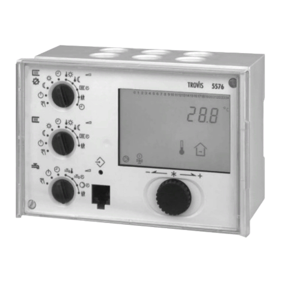
- Page 1 TROVIS 5500 Automation System TROVIS 5576 Heating and District Heating Controller Mounting and Operating Instructions EB 5576 EN Firmware version 2.41 ® Edition July 2018 Electronics from SAMSON...
- Page 2 Safety instructions Safety instructions The device may only be assembled, started up or operated by trained and experienced personnel familiar with the product. Proper shipping and ap- propriate storage are assumed. The controller has been designed for use in electrical power systems. For wiring and maintenance, you are required to observe the relevant safety regulations.
- Page 3 Revisions to controller firmware in comparison to previous versions Revisions to controller firmware in comparison to previous versions 1.90 1.95 (new) (previous) The priority operation (reverse control and set-back operation) can be set regardless of the time and temperature in the system. Refer to sections 6.9.1 and 6.9.2. The setting CO1 ->...
- Page 4 Revisions to controller firmware in comparison to previous versions 2.20 2.24 (new) (previous) Internal modifications 2.24 2.26 (new) (previous) Outdoor temperature using 0 to 10 V signal function extended Outdoor temperatures can be received or sent using a 0 to 10 V signal. 2.26 2.28 (new) (previous)
-
Page 5: Table Of Contents
Contents Contents Operation ....... 9 Operating elements ......9 1.1.1 Rotary pushbutton and changeover key . - Page 6 Contents 5.10 Flash adaptation......87 5.10.1 Flash adaptation without outdoor sensor (room temperature dependent) . 88 5.11 Adaptation .
- Page 7 Contents 7.12.4 Limitation of the calculated capacity....116 7.13 Device bus ......117 7.13.1 Requesting and processing an external demand .
- Page 8 Contents 12.6 Customer data ......172 Frequently used abbreviations ....190 EB 5576 EN...
-
Page 9: Operation
Operation Operation The controller is ready for use with the default temperatures and operating schedules. On start-up, the current time and date need to be set at the controller (–> section 1.5). Operating elements The operating controls are located in the front panel of the controller and protected by a Plexiglas door. -
Page 10: Rotary Switches
Operation 1.1.2 Rotary switches Use the three rotary switches to adjust the required operating mode (icons on the left) and the relevant parameters (icons on the right). The top and middle switches are assigned to the heating circuits (see page 169). The rotary switch in the middle is not used in systems without a second heating circuit. -
Page 11: Operating Modes
Operation Rotary switch to set the parameters of the DHW circuit Set point for DHW temperature Times-of-use for DHW heating Times-of-use for DHW circulation pump Party mode Note: If more than one rotary switch is set to position “Parameter“ (right side) at the same time, blinks on the display. -
Page 12: Display
Operation Display During operation, the display indicates the current time as well as information about the op- eration of the controller. The times-of-use are represented by black squares below the row of numbers at the top of the display. Icons indicate the operating status of the controller. STOP 10 11 13 14 15 16... -
Page 13: Displaying Data
Operation Displaying data The time, date, public holidays and vacation periods as well as the temperatures measured by the connected sensors and their set points can be retrieved and displayed with the help of the rotary pushbutton. Note: Data can also be viewed in the manual mode in the operating level. - Page 14 Operation Temperature at the flow sensor VF 0 1 2 3 4 5 6 7 8 9 10 11 12 13 14 15 16 17 18 19 20 21 22 23 24 °C : Heating circuit Rk1 : Heating circuit Rk2 Temperature at the flow sensor VF1, primary exchanger 0 1 2 3 4 5 6 7 8 9 10 11 12 13 14 15 16 17 18 19 20 21 22 23 24 circuit...
- Page 15 Operation 0 1 2 3 4 5 6 7 8 9 10 11 12 13 14 15 16 17 18 19 20 21 22 23 24 Temperature at the return flow sensor RüF, DHW circuit 0 1 2 3 4 5 6 7 8 9 10 11 12 13 14 15 16 17 18 19 20 21 22 23 24 ˚C ˚C Temperature at the storage tank sensor SF1 (DHW storage...
- Page 16 Operation Temperature at the storage tank sensor SF4 (buffer tank) 0 1 2 3 4 5 6 7 8 9 10 11 12 13 14 15 16 17 18 19 20 21 22 23 24 ˚C Temperature at the flow sensor VF4 0 1 2 3 4 5 6 7 8 9 10 11 12 13 14 15 16 17 18 19 20 21 22 23 24 °C Compare set point/limit and actual value.
-
Page 17: Setting The Controller Time
Operation Setting the controller time The current time and date need to be set immediately after start-up and after a power failure of more than 24 hours has occurred. This is the case when the time blinks on the display. Proceed as follows: Turn the top rotary switch to position “Controller... -
Page 18: Setting The Times-Of-Use
Operation Setting the times-of-use Three times-of-use can be set for each day of the week. If only one time-of-use is required, the start and stop times of the second time-of-use must be set to identical times. In this case, the third time-of-use is not displayed. If only two times-of-use are required, the start and stop times of the third time-of-use must be set to identical times. - Page 19 Operation Turn appropriate rotary switch to position Proceed as follows: “Times-of-use”. Display shows: 1–7 0 1 2 3 4 5 6 7 8 9 10 11 12 13 14 15 16 17 18 19 20 21 22 23 24 Select period/day for which the times-of-use are to be valid: 1–7 = every day, 1 = Monday, 2 = Tuesday, ..., 7 = Sunday...
-
Page 20: Setting The Party Mode
Operation Setting the party mode Using the Party mode function, the controller continues or activates the rated operation of the controller during the time when the party timer is active, regardless of the programmed times-of-use. The party timer begins when the rotary switch has been returned to operating mode “Automatic“. -
Page 21: Activating Extended Operating Level
Operation Activating extended operating level After the key number 1999 has been entered, the following information can be viewed and edited after the data points listed in section 1.4 have been displayed: Heat capacity Flow rate Public holidays (can be changed) Vacation periods (can be changed) Valve positions... -
Page 22: Setting Public Holidays
Operation 1.8.1 Setting public holidays On public holidays, the times-of-use specified for Sunday apply. A maximum of 20 public holidays may be entered. Level / Range of values Parameter Public holidays – Extended operating level / 01.01 (1 Jan) to 31.12 (31 Dec) Proceed as follows: In extended operating level, select “Public holidays“. -
Page 23: Setting Vacation Periods
Operation 1.8.2 Setting vacation periods During vacation periods, the controller constantly remains in reduced operating mode. A maximum of 10 vacation periods can be entered. Each vacation period can be separately assigned to the heating circuits Rk1 and Rk2 and/or the DHW circuit. Parameters Level / Range of values Vacation period (START, STOP) - Page 24 Operation Exit data point for vacation periods. Note: Vacation periods can also be entered in parameter level PA5 (–> section 2.3). Deleting vacation periods: Under data point for vacation periods, select the start date of the period you wish to de- lete.
-
Page 25: Setting Room And Dhw Temperature Set Points
Operation Setting room and DHW temperature set points For the heating circuits, the desired room temperatures during the day (Day set point) and during the night (Night set point) can be entered into the controller. In the DHW circuit, the temperature you wish the DHW to be heated to can be set. The temperature set points for the different control circuits are set at the rotary switches one after the other: Desired temperature set point... - Page 26 Operation Operating level (display of time and operation, see section 1) & key number Configuration and parameter level (start-up, see section 2) PA1/CO1: Heating circuit Rk1 ( CO7: Device bus PA2/CO2: Heating circuit Rk2 ( CO8: Initialization of free inputs PA4/CO4: DHW heating Anl: System code number...
-
Page 27: Start-Up
Start-up Start-up The modifications of the controller configuration and parameter settings described in this sec- tion can only be performed after the valid key number has been entered. The valid key number for initial start-up can be found on page 191. To avoid unauthorized use of the key number, remove the page or make the key number unreadable. -
Page 28: Activating And Deactivating Functions
Start-up Activating and deactivating functions A function is activated or deactivated in the associated function block. The numbers 0 to 24 in the top row of the display represent the respective function block numbers. When a config- uration level is opened, the activated function blocks are indicated by a black square on the right-hand side below the function block number. -
Page 29: Changing Parameters
Start-up Deactivate the function block. Display shows: F__ - 0 Confirm settings. If the function block is not closed, further function block parameters can be adjusted. Proceed as follows: Make the desired changes and confirm. If applicable, the next function block parameter is displayed. Confirm all parameters to exit the opened function block. -
Page 30: Calibrating Sensors
Start-up Proceed as follows: Switch to configuration and parameter level. Display shows: 0 0 0 0 Set valid key number. Confirm key number. Display shows: PA1 Select parameter level (-> Fig. 2). Open parameter level. Select desired parameter. Activate editing mode for the parameter. Edit the parameter. - Page 31 Start-up sor, the currently displayed sensor value must be changed such that it matches the tempera- ture (reference temperature) measured directly at the point of measurement. Sensor calibration is to be activated in CO5 via function block F20. An incorrect sensor calibration can be deleted by setting F20 - 0. Proceed as follows: Switch to configuration and parameter level.
- Page 32 Start-up Flow sensor VF 0 1 2 3 4 5 6 7 8 9 10 11 12 13 14 15 16 17 18 19 20 21 22 23 24 °C : Heating circuit Rk1 : Heating circuit Rk2 Flow sensor VF1, primary heat exchanger circuit 0 1 2 3 4 5 6 7 8 9 10 11 12 13 14 15 16 17 18 19 20 21 22 23 24 ˚C Flow sensor VF2, DHW circuit...
- Page 33 Start-up Return flow sensor RüF, DHW circuit 0 1 2 3 4 5 6 7 8 9 10 11 12 13 14 15 16 17 18 19 20 21 22 23 24 ˚C Storage tank sensor SF1 (DHW storage tank) 0 1 2 3 4 5 6 7 8 9 10 11 12 13 14 15 16 17 18 19 20 21 22 23 24 °C Storage tank sensor SF2 (DHW storage tank)
- Page 34 Start-up 0 1 2 3 4 5 6 7 8 9 10 11 12 13 14 15 16 17 18 19 20 21 22 23 24 Storage tank sensor SF2, SF3 (buffer tank) ˚C Storage tank sensor SF4 (buffer tank) 0 1 2 3 4 5 6 7 8 9 10 11 12 13 14 15 16 17 18 19 20 21 22 23 24 ˚C Flow sensor VF4...
-
Page 35: Resetting To Default Values
Start-up Resetting to default values All parameters in parameter levels PA1, PA2 and PA5 set over the rotary switches, except for the maximum flow temperature and the return flow temperature limits in PA1/PA2, can be reset to their default settings (WE). Proceed as follows: Switch to configuration and parameter level. -
Page 36: Manual Operation
Manual operation Manual operation Switch to manual mode to configure all outputs (see wiring diagram in section 11). The manual operation for the different control circuits is set at the rotary switches: Manual operation Rotary switch Position Heating circuit 1* Heating circuit 2* Middle DHW heating*... -
Page 37: Systems
Systems Systems Various hydraulic schematics are available. The systems can be configured both as primary and secondary systems. The fundamental hy- draulic differences between a primary and a secondary system are illustrated in Fig. 3. 1. A mixing valve replaces the heat exchanger in the heating/DHW circuit 2. - Page 38 Systems Boiler systems: Single-stage boiler systems can be configured to include any system whose heating circuits and DHW circuit include just one heat exchanger. These systems are Anl 1.0, 1.5 to 1.8, 2.x, 3.x, 4.0 to 4.3, 7.x, 8.x and 16.x. The boiler can be controlled by an on/off output (CO1 ->...
- Page 39 Systems System Anl 1.0 RK1/Y1 RüF1 Default settings CO1 -> F01 - 0 (without RF1) CO1 -> F02 - 1 (with AF1) CO1 -> F03 - 1 (with RüF1) EB 5576 EN...
- Page 40 Systems Systems Anl 1.1 to 1.4 heating Unfold back cover! RK1/Y1 VF1 RüF1 RF1 System Anl 1.1 Anl 1.2 Anl 1.3 Anl 1.4 Type of DHW heating Type 1 Type 2 Type 3 Type 4 XX = Integration of flow sensor VF4 Possible Possible Possible...
- Page 41 Systems Systems Anl 1.5 and 1.7 heating Unfold back cover! RK1/Y1 RüF1 System Anl 1.5 Anl 1.7 Type of DHW heating Type 1 Type 3 Integration of flow sensor VF4 Not possible Not possible Default settings CO1 -> F03 - 1 (with RüF1) CO4 ->...
- Page 42 Systems Systems Anl 1.6 and 1.8 heating Unfold back cover! RK1/Y1 RüF1 Anl 1.6 Anl 1.8 Anl 1.6 Anl 1.8 System With pre-control With pre-control W/o pre-control W/o pre-control Type of DHW heating Type 2 Type 4 Type 2 Type 4 •...
- Page 43 Systems System Anl 1.9 RüF2 RK2/Y2 BE17 Anl 1.9 Anl 1.9 System With pre-control Without pre-control Integration of VF4, UP2 Note – VF2 takes the position of VF4 Default settings CO4 -> F01 - 0 (without SF1) CO4 -> F03 - 0 (without RüF2) CO4 ->...
- Page 44 Systems System Anl 2.0 RK1/Y1 RüF1 VF1 UP1 SLP (Rk2) Default settings CO1 -> F01 - 0 (without RF1) CO1 -> F02 - 1 (with AF1) CO1 -> F03 - 1 (with RüF1) CO4 -> F01 - 1 (with SF1) CO4 ->...
- Page 45 Systems Systems Anl 2.1 to 2.4 DHW- heating Unfold back cover! RK1/Y1 RüF1 System Anl 2.1 Anl 2.2 Anl 2.3 Anl 2.4 Type of DHW heating Type 1 Type 2 Type 3 Type 4 XX = Integration of flow sensor VF4 Not possible Possible Not possible...
- Page 46 Systems System Anl 3.0 RK1/Y1 RK2/Y2 RüF2 RüF1 Default settings CO1 -> F02 - 1 (with AF1) CO1 -> F03 - 1 (with RüF1) CO2 -> F01 - 0 (without RF2) CO2 -> F03 - 0 (without RüF2) EB 5576 EN...
- Page 47 Systems Systems Anl 3.1 to 3.4 heating Unfold back cover! RK1/Y1 RK2/Y2 RüF2 RüF1 System Anl 3.1 Anl 3.2 Anl 3.3 Anl 3.4 Type of DHW heating Type 1 Type 2 Type 3 Type 4 XX = Integration of flow sensor VF4 Not possible Possible Not possible...
- Page 48 Systems System Anl 3.5 RK1/Y1 RüF1 Control and UP1 are only active during processing for external Note demand. Default setting CO1 -> F03 - 1 (with RüF1) EB 5576 EN...
- Page 49 Systems System Anl 4.0 RK1/Y1 RK2/Y2 RüF2 RüF1 Default settings CO1 -> F01 - 0 (without RF1) CO1 -> F02 - 1 (with AF1) CO1 -> F03 - 1 (with RüF1) CO2 -> F01 - 0 (without RF2) CO2 -> F02 - 0 (without AF2) CO2 ->...
- Page 50 Systems Systems Anl 4.1 to 4.3 DHW heating Unfold back cover! RK1/Y1 RK2/Y2 RüF2 RüF1 System Anl 4.1 Anl 4.2 Anl 4.3 Type of DHW heating Type 1 Type 2 Type 3 XX = Integration of VF4 Not possible Possible Not possible ZP integration (broken line) –...
- Page 51 Systems System Anl 4.5 RK1/Y1 RK2/Y2 RüF2 RüF1 Default settings CO1 -> F01 - 0 (without RF1) CO1 -> F02 - 1 (with AF1) CO1 -> F03 - 1 (with RüF1) CO2 -> F01 - 0 (without RF2) CO2 -> F02 - 0 (without AF2) CO2 ->...
- Page 52 Systems Systems Anl 7.1 and 7.2 heating Unfold back cover! RK1/Y1 RK2/Y2 RüF1 RüF2 System Anl 7.1 Anl 7.2 Type of DHW heating Type 1 Type 2 XX = Integration of VF4 Not possible Possible ZP integration (broken line) – Possible with CO4 ->...
- Page 53 Systems Systems Anl 8.1 and 8.2 DHW heating Unfold back cover! RüF1 RK2/Y2 RK1/Y1 RüF2 System Anl 8.1 Anl 8.2 Type of DHW heating Type 1 Type 2 XX = Integration of VF4 Not possible Possible ZP integration (broken line) –...
- Page 54 Systems System Anl 10.0 RK2/Y2 RüF2 RK1/Y1 RüF1 Default settings CO1 -> F01 - 0 (without RF1) CO1 -> F02 - 1 (with AF1) CO1 -> F03 - 1 (with RüF1) CO2 -> F01 - 0 (without RF2) CO2 -> F02 - 0 (without AF2) CO2 ->...
- Page 55 Systems Systems Anl 10.1 to 10.3 DHW heating Unfold back cover! RK1/Y1 RüF1 RK2/Y2 RüF2 System Anl 10.1 Anl 10.2 Anl 10.3 Type of DHW heating Type 1 Type 2 Type 3 XX = Integration of VF4 Possible Possible Possible ZP integration (broken line) –...
- Page 56 Systems System Anl 10.5 RK2/Y2 RüF2 RK1/Y1 RüF1 Default settings CO1 -> F01 - 0 (without RF1) CO1 -> F03 - 1 (with RüF1) CO2 -> F01 - 0 (without RF1) CO2 -> F03 - 1 (with RüF2) EB 5576 EN...
- Page 57 Systems Systems Anl 11.0 and 11.3 DHW heating Unfold back cover! RK2/Y2 RK1/Y1 RüF1 RüF2 System Anl 11.0 Anl 11.3 Type of DHW heating Type 1 Type 3 Integration of VF4 Not possible Not possible ZP integration (broken line) – –...
- Page 58 Systems System Anl 11.1 RK2/Y2 RüF2 VF2 UP1 RK1/Y1 RüF1 RF1 Default settings CO1 -> F01 - 0 (without RF1) CO1 -> F02 - 1 (with AF1) CO1 -> F03 - 1 (with RüF1) CO4 -> F01 - 1 (with SF1) CO4 ->...
- Page 59 Systems System Anl 11.2 RK2/Y2 RK1/Y1 RüF1 RüF2 Anl 11.2 Anl 11.2 System With pre-control Without pre-control Type of DHW heating Type 2 Type 2 • Integration of VF4, UP2 – ZP integration (broken line) Possible Possible with CO4 -> F10 - 1 Note –...
- Page 60 Systems System Anl 11.1/11.2 with buffer tank RüF1 RüF2 Default settings CO1 -> F01 - 0 (without RF1) CO1 -> F02 - 1 (with AF1) CO1 -> F03 - 1 (with RüF1) CO4 -> F01 - 1 (with SF1) Anl 11.1 - 0 (without SF2) CO4 ->...
- Page 61 Systems System Anl 11.4 RK2/Y2 RK1/Y1 RüF1 RüF2 ZP integration (broken line) Possible with CO4 -> F10 - 1 Default settings CO1 -> F01 - 0 (without RF1) CO1 -> F02 - 1 (with AF1) CO1 -> F03 - 1 (with RüF1) CO4 ->...
- Page 62 Systems System Anl 11.4 with buffer tank RüF2 RüF1 Default settings CO1 -> F01 - 0 (without RF1) CO1 -> F02 - 1 (with AF1) CO1 -> F03 - 1 (with RüF1) CO4 -> F01 - 1 (with SF1) CO4 -> F02 - 1 (with SF2) CO4 ->...
- Page 63 Systems System Anl 11.5 RK1/Y1 RüF1 RüF2 Note DHW circuit with adjustable valve position for storage tank charging in absolute priority operation. By using RüF2, the ready-adjusted valve position is governed by the return flow temperature limitation. Default settings CO1 -> F01 - 0 (without RF1) CO1 ->...
- Page 64 Systems System Anl 11.6 RK2/Y2 RK1/Y1 RüF1 RüF2 SLP/ZP *Note: The pump in the DHW circuit is designed to run constantly. There- fore, it must connected directly to the mains supply. Default settings CO1 -> F01 - 0 (without RF1) CO1 ->...
- Page 65 Systems System Anl 11.9 RüF2 RK2/Y2 RK1/Y1 RüF1 BE17 Anl 11.9 Anl 11.9 System With pre-control Without pre-control Integration of VF4, UP2 Note – VF2 takes the position of VF4 Default settings CO1 -> F01 - 0 (without RF1) CO1 -> F02 - 1 (with AF1) CO1 ->...
- Page 66 Systems Systems Anl 14.1 and 14.2 heating Unfold back cover! RÜF1 BA8 BA9 RK1/Y1 System Anl 14.1 Anl 14.2 Type of DHW heating Type 1 Type 2 XX = Integration of UP1 Possible Not possible Default settings CO1 -> F02 - 1 (with AF1) - 1 (with AF1) CO1 ->...
- Page 67 Systems System Anl 14.3 RÜF1 BA8 BA9 SF1 UP2 RÜF2 SF4/VF4 RK1/Y1 Default settings CO1 -> F02 - 1 (with AF1) CO1 -> F03 - 1 (with RüF1) CO4 -> F01 - 1 (with SF1) EB 5576 EN...
- Page 68 Systems System Anl 16.0 RK1/Y1 RüF1 Default settings CO1 -> F02 - 1 (with AF1) CO1 -> F03 - 1 (with RüF1) EB 5576 EN...
- Page 69 Systems System Anl 16.1 RK1/Y1 RüF2 RK2/Y2 RüF1 Default settings CO1 -> F02 - 1 (with AF1) CO1 -> F03 - 1 (with RüF1) CO2 -> F01 - 0 (without RF2) CO2 -> F02 - 0 (without AF2 for Rk2) CO2 ->...
- Page 70 Systems System Anl 16.2 RK1/Y1 RüF1 Default settings CO1 -> F02 - 1 (with AF1) CO1 -> F03 - 1 (with RüF1) EB 5576 EN...
- Page 71 Systems System Anl 16.3 RK1/Y1 RüF2 SF3 SF1 RüF1 Default settings CO1 -> F02 - 1 (with AF1) CO1 -> F03 - 1 (with RüF1) EB 5576 EN...
- Page 72 Systems System Anl 16.4 RK1/Y1 RüF2 RüF1 Default settings CO1 -> F02 - 1 (with AF1) CO1 -> F03 - 1 (with RüF1) EB 5576 EN...
- Page 73 Systems System Anl 16.6 RK1/Y1 RüF2 SF3 SF1 RüF1 RK2/Y2 Default settings CO1 -> F02 - 1 (with AF1) CO1 -> F03 - 1 (with RüF1) CO2 -> F01 - 0 (without RF2) CO2 -> F02 - 0 (without AF2 for Rk2) CO2 ->...
-
Page 74: Functions Of The Heating Circuit
Functions of the heating circuit Functions of the heating circuit Which controller functions are available depends on the selected system code number (Anl). Weather-compensated control When weather-compensated control is used, the flow temperature is controlled according to the outdoor temperature. The heating characteristic in the controller defines the flow tempera- ture set point as a function of the outdoor temperature (–>... -
Page 75: Gradient Characteristic
Functions of the heating circuit Receive value AF2 CO7 -> F09 - 1; register no. 5.1.1 Gradient characteristic Basically, the following rule applies: a decrease in the outdoor temperature causes the flow temperature to increase. By varying the parameters Gradient and Level, you can adapt the characteristic to your indi- vidual requirements: The gradient needs to be increased if the room temperature [°C]... - Page 76 Functions of the heating circuit The level needs to be decreased and the gradient increased [°C] if the room temperature rises when it is mild outside. –20 [°C] Outside the times-of-use, reduced set points are used for control: The reduced flow set point is calculated as the difference between the adjusted values for Day set point (rated room temperature) and Night set point (reduced room temperature).
-
Page 77: Four-Point Characteristic
Functions of the heating circuit 5.1.2 Four-point characteristic The four-point characteristic allows you to define your own heating characteristic. It is defined by four points each for the Outdoor temperature, the Flow temperature, the Re- duced flow temperature and the Return flow temperature. The Max. flow temperature and Min. flow temperature parameters mark the upper and lower limits of the flow temperature. -
Page 78: Fixed Set Point Control
Functions of the heating circuit Parameter level / Range of values Parameters Flow temperature Point 1 70 °C PA1, 2 / –5 to 150 °C Point 2 55 °C Point 3 40 °C Point 4 25 °C Reduced flow temperature Point 1 60 °C PA1, 2 / –5 to 150 °C... -
Page 79: Underfloor Heating/Drying Of Jointless Floors
Functions of the heating circuit Note: A fixed set point control in heating circuit 2 with CO2 -> F02 - 0 can only be config- ured if CO1 -> F02 - 0 is set as well, because the heating circuit 2 with CO2 -> F02 - 0 only uses the measured outdoor temperature provided by heating circuit 1. -
Page 80: Deactivation Depending On Outdoor Temperature
Functions of the heating circuit The drying process has been successfully completed when the additional icon in the flow tem- perature display goes out after the last phase. Any power failure that occurs while the func- tion is running automatically restarts the drying function. In systems in which the drying function is interrupted due to DHW heating (e.g. -
Page 81: Ot Activation Value In Rated Operation
Functions of the heating circuit ture falls below this value (less 0.5 °C hysteresis), heating operation is restarted immediately. With the default settings, this means that, at night, the system is switched off at an outdoor temperature of 15 °C to save energy. Nevertheless, remember that the system requires some time in the morning to heat up the building. - Page 82 Functions of the heating circuit storage tank is completed, the buffer tank can be charged. In system Anl 14.3, a solar circuit with reroutable heat transfer medium flow is integrated. If the temperature difference be- tween the collector sensor RüF2 and one of the tank storage sensors SF3 or SF4 is greater than the Solar circuit pump ON, the solar circuit pump UP2 is switched on and the corre- sponding storage tank is charged.
- Page 83 Functions of the heating circuit Note: The buffer tank control circuit is deactivated as described in section x. When prede- fined gradients of heating characteristic (CO1 > F11 - 0) are used, night mode is not possi- ble in the buffer tank control circuit. In contrast to an active four-point characteristic (CO1 > F11 - 1): in this case, a four-point characteristic exists for day and night modes.
-
Page 84: Summer Mode
Functions of the heating circuit Configuration Functions Storage tank sensor SF2 CO1 -> F06 - 1 SLP depending on return flow CO1 -> F22 - 1 temperature Parameter Parameter level / Range of values Minimum set point to charge buffer PA1 / AT to 90 °C tank Stop charging of the buffer tank... -
Page 85: Delayed Outdoor Temperature Adaptation
Functions of the heating circuit Delayed outdoor temperature adaptation The calculated outdoor temperature is used to determine the flow temperature set point. The heat response is delayed when the outdoor temperature either decreases, increases or in- creases and decreases. If the outdoor temperature varies by, for example, 12 °C within a very short period of time, the calculated outdoor temperature is adapted to the actual out- door temperature in small steps. -
Page 86: Optimization
Functions of the heating circuit Configuration Functions Room sensors RF1/2 CO1, 2 -> F01 - 1 If the TROVIS 5570 Room Panel is to be used, the following additional configurations must be made: Device bus CO7 -> F01 - 1; device bus address TROVIS 5570 Room Panel in Rk1 CO7 ->... -
Page 87: Flash Adaptation
Functions of the heating circuit icons blink on the display. Outside the times-of-use, the controller monitors the Night set point (reduced room temperature). When the temperature falls below the night set point, the controller heats with the max. flow temperature until the measured room tempera- ture exceeds the adjusted value by 1 °C. -
Page 88: Flash Adaptation Without Outdoor Sensor (Room Temperature Dependent)
Functions of the heating circuit Configuration Functions Room sensors RF1/2 CO1, 2 -> F01 - 1 Flash adaptation CO1, 2 -> F09 - 1 20 min Cycle time / 1 to 100 min (gain) / 0 to 25 Parameters Rotary switch / Range of values Day set point 20 °C Top, middle / 0 to 40 °C... -
Page 89: Adaptation
Functions of the heating circuit 5.11 Adaptation The controller is capable of automatically adapting the heating characteristic to the building characteristics, provided a gradient characteristic has been set (CO1, 2 -> F11 - 0). The ref- erence room, where the room sensor is located, represents the entire building and is moni- tored to ensure that the room set point (Day set point) is maintained. -
Page 90: Cooling Control
Functions of the heating circuit Fault indication output CO5 -> F07 - 0 BA13 BA12 ON during thermal CO4 -> F17 - 0 disinfection BA12 ON during DHW de- CO4 -> F18 - 0 mand CO5-> F17 - 0 or -1 only influences the switching state of binary output BA13! 5.13 Cooling control Cooling control with outdoor sensor When the cooling control function is activated in a control circuit, the four-point characteristic... - Page 91 Functions of the heating circuit Parameters Parameter level / Range of values Base point of return flow 65 °C PA1, 2 / 5 to 90 °C temperature Note: The limiting factors of the Return flow sensor RüF1/RüF2 (CO1, 2 -> F03) functions apply during cooling control as well.
-
Page 92: Differential Temperature Control
Functions of the heating circuit 5.14 Differential temperature control In systems Anl 1.0 and 16.0, the differential temperature control causes the delivery rate of pump UP1 to be adapted through the 0 to 10 V output depending on the difference between the secondary flow temperature and the secondary return flow temperature. -
Page 93: Functions Of The Dhw Circuit
Functions of the DHW circuit Functions of the DHW circuit DHW heating in the storage tank system Start storage tank charging Storage tank charging pump Storage sensor 1 Circulation pump Hot water Cold water Fig. 8 · Schematics of a storage tank system The controller begins charging the storage tank when the water temperature measured at sensor SF1 falls below the DHW temperature set point by 0.1 °C. - Page 94 Functions of the DHW circuit Time-controlled switchover of storage tank sensors By configuring a second storage tank sensor SF2 over the function block CO4 -> F19 - 1, it is possible to determine that the storage tank sensor SF1 is used for day mode in the DHW circuit and that the storage tank sensor SF2 is used for night mode.
-
Page 95: Dhw Circuit Additionally Controlled By A Globe Valve
Functions of the DHW circuit Parameter level / Range of values Parameters Charging temperature boost*** 10 °C PA4 / 0 to 50 °C Lag of storage tank charging pump PA4 / 0 to 10.0 Sustained DHW temperature 40 °C PA4 / 5 to 90 °C Parameters serve as limitation of the adjustment range for the DHW temperature to be set at the rotary switch ** Deactivation value T = DHW temperature + Hysteresis... -
Page 96: Dhw Heating In The Storage Tank Charging System
Functions of the DHW circuit DHW heating in the storage tank charging system Start storage tank charging Exchanger charging pump Flow sensor Storage tank charging pump Storage sensor 1 Storage sensor 2 Circulation pump Hot water Cold water Fig. 10 · Schematics of a storage tank charging system The controller begins charging the storage tank when the water temperature measured at sensor SF1 falls below the DHW temperature set point by 0.1 °C. - Page 97 Functions of the DHW circuit Note: The set point in the heat exchanger circuit which is valid at the end of the charging cycle will be used again at the beginning of the next cycle. If times-of-use have been programmed for DHW heating, the DHW temperature set point adjusted at the rotary switch is applied during these times-of-use.
-
Page 98: Cold Charging Protection
Functions of the DHW circuit Parameter level / Range of values Parameters Hysteresis** 5 °C PA4 / 0 to 30 °C Charging temperature boost*** 10 °C PA4 / 0 to 50 °C Max. charging temperature 80 °C PA4 / 20 to 150 °C (only with VF4) Lag of storage tank charging pump PA4 / 0 to 10.0 Sustained DHW temperature... -
Page 99: Dhw Heating In Instantaneous Heating System
Functions of the DHW circuit DHW heating in instantaneous heating system Flow sensor Circulation pump Hot water Cold water Water flow sensor Fig. 11 · Schematics of an instantaneous heating system with water flow sensor (CO4 -> F04 - 1, select: AnA) Without a water flow sensor or flow switch, the required DHW temperature at sensor VF is only regulated during the times-of-use of the circulation pump ZP. -
Page 100: Dhw Heating With Solar System
Functions of the DHW circuit DHW heating with solar system The systems Anl 1.3, 1.4, 1.7, 1.8, 2.3, 2.4, 3.3, 3.4, 4.3, 10.3, 11.3 and 11.4 include a solar system for DHW heating. In these systems, the difference between the temperatures measured at storage sensor SF3 and the sensor at the solar collector VF3 is determined. -
Page 101: Speed Control Of The Charging Pump
Functions of the DHW circuit perature for parallel pump operation. In this case, the controller applies priority operation, if necessary with intermediate heating. Once a parallel pump operation cycle has been acti- vated and the time for Stop parallel operation in case of deviation has elapsed, system devi- ations greater than 5 °C cause the controller to suspend parallel operation for 10 minutes and to apply priority operation. -
Page 102: Priority Operation
Functions of the DHW circuit Circulation pump operation CO4 -> F11 during storage tank charging Priority operation In many district heating systems with primary DHW heating, the allotted amount of water does not cover the DHW heating and the heating system at the same time. As a result, the capacity required for DHW heating needs to be taken from the heating system when great heating loads occur;... -
Page 103: Set-Back Operation
Functions of the DHW circuit Priority through reverse control CO4 -> F08 - 1 2 min Activate priority in case of deviation / 0 to 10 min Correction factor / 0.1 to 10.0 Control circuit selection / Rk1, Rk2, Rk1 + Rk2 (see above) Priority through set-back operation 0 CO4 ->... -
Page 104: Thermal Disinfection
Functions of the DHW circuit 6.11 Thermal disinfection In all systems with DHW heating, the DHW storage tank is thermally disinfected on a selected Day of the week or every day. In systems with DHW storage tank, it is heated up, taking into account the Charging tem- perature boost parameter (or Set point boost, depending on the system) to the adjusted Disinfection temperature. - Page 105 Functions of the DHW circuit Note: This function is not available when a storage tank thermostat is used. Controllers that are linked over a device bus are subjected to return flow temperature limitation in the primary control circuit even during the thermal disinfection in a secondary controller.
-
Page 106: System-Wide Functions
System-wide functions System-wide functions Automatic summer/standard time swichover The clock is automatically adjusted on the last Sunday in March at 2.00h and on the last Sunday in October at 3.00h. Configuration Function CO5 -> F08 - 1 Summer/standard time switchover Frost protection Frost protection measures are taken when the outdoor temperature falls below the Frost pro- tection limit. -
Page 107: Forced Operation Of The Pumps
System-wide functions Forced operation of the pumps When the heating circuit pumps have not been activated for 24 hours, forced operation of the pumps is started between 12.02h and 12.03h. This is done to avoid that the pumps get stuck when they are not operated for a longer period of time. In the DHW circuit, the circula- tion pump is operated between 12.04h and 12.05h, the other pumps between 12.05h and 12.06h. -
Page 108: Condensate Accumulation Control
System-wide functions Configuration Functions Return flow sensors RüF1/2 CO1, 2, 4 -> F03 - 1 Limiting factor / 0.1 to 10.0 Return flow temperature CO5 -> F16 limitation with P algorithm Parameters Parameter level / Range of values Gradient, return flow PA1, 2 / 0.2 to 3.2 Level, return flow 0.0 °C... -
Page 109: Three-Step Control
System-wide functions Three-step control The flow temperature can be controlled using a PI algorithm. The valve reacts to pulses that the controller sends when a system deviation occurs. The length of the first pulse, in particu- lar, depends on the extent of the system deviation and the selected Proportional gain K (the pulse length increases as K increases). -
Page 110: Releasing A Control Circuit/Controller Over The Binary Input
System-wide functions change performed by the proportional component (the greater T , the slower the rate of change). Due to the derivative component, any change of the system deviation is incorpo- rated into the output signal with a certain gain (the greater T , the stronger the change). -
Page 111: Speed Control Of The Charging Pump
System-wide functions 7.10 Speed control of the charging pump This function allows the delivery rate of the charging pump in systems with buffer tank (CO1 > F21-1) and in systems with DHW storage tank (CO4 > F21-1) to be varied based on the temperature. - Page 112 System-wide functions Note: Overheating may occur in the heating circuits of the primary controller without control valve. Excessive charging temperatures in DHW circuits without control valve controlled by the pri- mary controller are excluded when the default settings of the controller are used: while stor- age tank charging is active, no flow temperature higher than the charging temperature is used by the primary controller.
-
Page 113: Flow Rate/Capacity Limitation In Rk1
System-wide functions Configuration Functions Processing an external demand, binary CO1 -> F17 - 0 Parameter level / Range of values Parameter Set point boost of primary exchanger control 5 °C PA1, 2 / 0 to 50 °C 7.12 Flow rate/capacity limitation in Rk1 Flow rate/capacity limitation can be implemented based on a pulse or standardized signal of 0/4 to 20 mA provided by the heat meter. -
Page 114: Limitation Using 0/4 To 20 Ma Signal
System-wide functions troller does not distinguish between a flow rate pulse signal or a capacity pulse signal. As the displayed current pulse rate P [pulse/h] (–> Extended operating level, key number 1999) is calculated depending on the interval between the received pulses, it is natural that the con- troller cannot react immediately to all rapid flow rate or capacity changes which occur in the system. -
Page 115: Creep Feed Rate Limitation Using A Binary Input
System-wide functions When the flow rate reaches the current Max. limit value, the flow set point of control circuit Rk1 is reduced. How strongly the controller responds is determined by the Limiting factor. Note: If CO5 -> F00 - 1 is indicated, access to the return flow, flow rate and heat capacity settings are locked. -
Page 116: Limitation Of The Calculated Capacity
System-wide functions 7.12.4 Limitation of the calculated capacity The controller is able to calculate the heat capacity used in the system and to limit it depend- ing on the operational circumstances. To achieve this, it uses a connected 0/4 to 20 mA sig- nal for the flow rate, a primary return flow sensor and a primary flow sensor. -
Page 117: Device Bus
System-wide functions 7.13 Device bus Using the device bus, it is possible to connect up to 32 device from the Series 55xx. For con- nection, the TROVIS 5576 Controller is, above all, equipped with the terminals 29/30. No attention must be paid to the polarity of the device bus wiring. Danger of short circuit! If several TROVIS 5576 Controllers in one plant are to be connected to the building control station using the system bus interface and the cable converter 1400-8800, remember that all... - Page 118 System-wide functions The primary controller compares the received requested demands and its own requested de- mands and supplies the system with the required flow temperature – if necessary increased by the value of the Set point boost of primary exchanger control parameter. Note: Overheating may occur in heating circuits of the primary controller without control valve.
-
Page 119: Sending And Receiving Outdoor Temperatures
System-wide functions used by the primary controller. Nevertheless, if the Priority for external demand function is activated, the external demand is also processed during storage tank charging. Configuration Function Priority for external demand CO4 -> F16 - 1 7.13.2 Sending and receiving outdoor temperatures Controllers equipped with one (two) outdoor sensor(s) can be configured to supply other con- trollers with the measured outdoor temperature(s) over the device bus. -
Page 120: Priority Over All Controllers
System-wide functions 7.13.4 Priority over all controllers It is possible to put the heating circuits of other controllers out of operation while the DHW heating is active when the controllers are linked to one another over a device bus. The return flow temperature limitation in the primary circuit can also be raised to the adjusted value for Maximum return flow temperature or for Point 1 of the return flow temperature in a four-point characteristic when the controller is configured correspondingly. -
Page 121: Display Error Messages Issued By The Device Bus
System-wide functions TROVIS 5570 TROVIS 5576 Y COM 12...26.5V AC/ 0...10V 15...36V DC 0...10V COM BA12, BA13 Pump management - COM BA12 UP1 On/off BA13 UP1 Speed Fig. 12 · Connecting the TROVIS 5570 Room Panel to the controller Functions Configuration Device bus CO7 ->... -
Page 122: Requesting An External Demand By Issuing A 0 To 10 V Signal
System-wide functions 7.14 Requesting an external demand by issuing a 0 to 10 V signal The controller can request a demand for the maximum flow set point (with boost, if need be) by issuing up to two analog 0 to 10 V signals for external demand with sequence control. For this purpose, the outputs Y1 to Y2 are used as an alternative to issuing the control signal. -
Page 123: Feeder Pump Operation
System-wide functions The measured values both in the measuring ranges from 0 to 2000 Ω do not appear on the controller display. They are only available as Modbus data points. Configuration Function Room sensor RF1, 2 CO1, 2 -> F01 - 0 Exceptions: CO1 ->... -
Page 124: Locking Manual Level
System-wide functions 7.18 Locking manual level To protect the heating system, this function can be used to lock the manual level. When this function has been activated, automatic mode is started when the rotary switch is set to Configuration Function Locking manual levels CO5 ->... -
Page 125: Operational Faults
Operational faults Operational faults A failure is indicated by the blinking icon on the display. In addition, the display is illumi- nated for 1 second in intervals of 10 seconds when a malfunction persists. The “Error“ mes- sage is immediately displayed. Press the rotary pushbutton to open the error level. It may be possible to view several error messages by turning the rotary pushbutton. -
Page 126: Temperature Monitoring
Operational faults Outdoor sensors AF 1/2: When the outdoor sensor fails, the controller uses a flow tem- perature set point of 50 °C or the Max. flow temperature when the Max. flow tempera- ture (adjusted under PA1, 2) is smaller than 50 °C. With the setting CO1, 2 > F05 - 1 (underfloor heating), the flow temperature set point is 30 °C in the event of a malfunction. -
Page 127: Error Status Register
Operational faults Error status register The error status register is used to register controller or system errors. The error messages which have an effect on the error status register are listed in the table in bold. Using the function blocks in the configuration level CO8, individual controller inputs that are not used can be assigned as binary inputs to the error status register. -
Page 128: Communication
(four-wire bus: SAMSON cable converter 1400-7308, two-wire bus: SAMSON cable converter 1400-8800) or SAMSON surge protection with in- Fig. 13 · Network structure tegrated converter (1400-9771). Note: Regardless of whether communication is established using a modem or data cable, the operating software can be updated using the serial system bus interface, provided Modbus has been activated (CO6 ->... -
Page 129: Description Of Communication Parameter Settings
Communication If there is no communication between the control system and the controller, interventions of the control system in dynamic processes can be limited with regard to time using the Control system monitoring function. While valid Modbus requests are registered, the controller resets the time monitoring. Never- theless, after 30 minutes have elapsed, all level bits are re-initialized to “autonomous“... -
Page 130: Meter Bus Interface
Communication Meter bus interface With the help of an optional, retrofittable meter bus plug-in module, the TROVIS 5576 Heating and District Heating Controller can communicate with up to 6 meter bus devices ac- cording to EN 1434-3. A flow rate or capacity limitation in every control circuit can be con- figured on the basis of the values measured at heat meters WMZ1 and WMZ2 for systems with two control circuits. -
Page 131: Flow Rate/Capacity Limitation Using Meter Bus
Communication Blinking values in combination with black squares in the top row of the display (error status of the associated meter –> TV-SK 6311) indicate various faults. The controller issues the “Err 9” or “Err 10” error messages. Note: With reading mode “24h“, the displayed values are not updated by reopening the lev- els “buS 1“... - Page 132 Communication As a result, three different maximum limit values can be adjusted in all systems with only one control valve and DHW heating on the secondary side: Max. limit value to determine the absolute upper limit Max. limit value for heating to operate only the room heating Max.
- Page 133 Communication Flow rate limitation in Rk2 using CO6 -> F13 - 1 meter bus Max. limit value / 0.01 to 650 Limiting factor / 0.1 to 10.0 * Icons of the maximum limit values on the display: System –> “Flow rate“ and “Fixed set point“ Heating –>...
-
Page 134: Memory Module/Mini Module
Communication * Icons of the maximum limit values on the display: System –> “Flow rate“ and “Fixed set point“ Heating –> “Flow rate“, “Fixed set point“ and “Radiator“ DHW –> “Flow rate“, “Fixed set point“ and “Tap“ Memory module/mini module The use of a memory module (accessory no. - Page 135 Communication function of the module. If no selection is made, data logging starts automatically after two minutes. The controller starts to write over the oldest data as soon the memory of the data logging module or integrated historical data memory is full. The current memory capacity of the data logging module can be read in the extended operating level under Info 2 as the second value in the sequence (range of values: 0 to 6035).
-
Page 136: Installation
Installation Installation Dimensions in mm W x H x D = 144 x 98 x 81 The controller consists of the housing with the electronics and the back panel with the termi- nals. It is suitable for panel, wall and top hat rail mounting (Fig. 14) Panel mounting 1. - Page 137 Installation Panel mounting Back of the controller Controller housing Wall mounting Top hat rail mounting Dimensions in mm W x H x D = 144 x 98 x 81 Fig. 14 · Installation EB 5576 EN...
-
Page 138: Electrical Connection
Electrical connection Electrical connection Risk of electric shock! – For electrical installation, you are required to observe the relevant electrotechnical regula- tions of the country of use as well as the regulations of the local power suppliers. Make sure all electrical connections are installed by trained and experienced personnel. Before performing any work on the controller, disconnect it from the power supply. - Page 139 Electrical connection Connecting the controller The controller is connected as illustrated in the diagram on page 141. Open the housing to connect the cables. To connect the feeding cables, make holes in the marked locations at the top, bottom or back of the rear part of the housing and fit suitable grommets or cable glands.
- Page 140 Electrical connection Assignment of the RJ-45 jack Device bus Device bus Fig.15 · Assignment of the RJ-45 jack Legend for wiring diagram (page 141): Outdoor sensor RüF Return flow sensor Binary output Storage sensor Binary input Storage tank charging pump Potentiometer Circulation pump Room sensor...
- Page 141 CAUTION! Never connect terminals 18 (ground of sensor), 19 (ground of 0 to 10 V/0 to 20 mA) and 20 (ground of 0 to 10 V outputs)! If the controller is equipped with a meter bus module, the TROVIS 5570 Room Panel cannot be supplied by the controller! To apply a 20 mA signal, a 50 Ω...
-
Page 142: Appendix
Appendix Appendix 12.1 Function block lists CO1: Heating circuit Rk1 (not Anl 1.9) Comment F Function Function block parameters / Range of values (default) 01 Room sensor RF1 Not in Anl CO1 -> F01 - 1: Temperature display and input FG1 for 1.5-1.8, Type 5244/5257-5 Room Panel active 3.x, 7.x,... - Page 143 Appendix Comment F Function Function block parameters / Range of values (default) • CO1 -> F01 - 1 08 Adaptation Not in Anl CO1 -> F08 - 1: Only with • CO1 -> F02 - 1 1.5-1.8, • CO1 -> F11 - 0 3.x, 7.x, 14.x, 16.x 09 Flash adaptation...
- Page 144 Appendix Comment F Function Function block parameters / Range of values (default) • CO1 -> F15 - 1 17 Processing an Not in CO1 -> F17 - 1: Only with • CO1 -> F16 - 0 external demand, systems binary with solar Options bE / 1, 0 (1) circuit, not...
- Page 145 Appendix CO2: Heating circuit Rk2 (systems Anl 3.0-3.4, 4.x, 10.x, 16.x)* Comment F Function Function block parameters / Range of values (default) 01 Room sensor RF2 All* CO2 -> F01 - 1: Temperature display and input FG2 for Type 5244/5257-5 Room Sensor active TROVIS 5570 Room Panel: CO2 ->...
- Page 146 Appendix Comment Function block parameters / Range of values (default) F Function 11 Four-point All* CO2 -> F11 - 1: Four-point characteristic, characteristic only with CO2 -> F08 - 0 CO2 -> F11 - 0: Gradient characteristic 12 Control mode All* CO2 ->...
- Page 147 Appendix CO4: DHW heating (Anl 1.1–1.9, 2.x, 3.1–3.4, 4.1–4.5, 7.x, 8.x, 10.1–10.3, 11.x, 14.x )* Comment Function block parameters / Range of values (default) F Function 01 Storage sensor CO4 -> F01 - 0 (not in Anl 11.0, 11.3): Storage tank thermostat, only with CO4 ->...
- Page 148 Appendix Comment F Function Function block parameters / Range of values (default) 08 Priority through 1.1–1.4, CO4 -> F08 - 1: Only with CO4 -> F09 - 0; reverse control 3.1–3.4, in systems Anl 10.x, only Rk2 is influenced 4.1–4.5, Function block parameters: 10.1–10.3, Activate priority in case of deviation / 0 to 10 min (2 min)
- Page 149 Appendix Comment F Function Function block parameters / Range of values (default) 14 Thermal All* CO4 -> F14 - 1: Only with CO4 -> F01 - 1 disinfection Function block parameters: Day of the week / 1, 2, ..., 7, 1–7 (3) Start time / 0:00h to 23:45h (0:00h);...
- Page 150 Appendix Comment F Function Function block parameters / Range of values (default) 21 Speed control of 1.5–1.8, CO4 > F21 - 1: Temperature-dependent adaptation of the charging pump 2.x, delivery rate of the charging pump at Y1 (0 to 10 V) 3.1–3.4, Controller output Function block parameters:...
- Page 151 Appendix Comment F Function Function block parameters / Range of values (default) 07 Fault indication With CO5 -> F07 - 1, the pump management function is not output BA13 available Function block parameter: bA / 1, 0 (1) 08 Automatic summer /standard time switchover 09 Frost protection...
- Page 152 Appendix Comment Function block parameters / Range of values (default) F Function 13 Capacity limitation CO5 -> F13 - 1 only with CO1 -> F03 - 1 and CO5 -> F11 - on the basis of a connected flow rate Connection of primary flow sensor at input FG2 signal in Rk1 Function block parameters:...
- Page 153 Appendix CO5´: System-wide functions (all systems) Comment Function block parameters / Range of values (default) F Function 01 Y1 reverse CO5´ -> F01 - 0: 0 V/0 % = Valve CLOSED/Pump OFF CO5´ -> F01 - 1: 0 V/0 % = Valve OPEN/Pump with max. delivery rate Function block parameters: Zero: 0 to 50 % (0 %)
- Page 154 Appendix Comment F Function Function block parameters / Range of values (default) 09 Reserved 10 Meter bus CO6 -> F10 - 1: Meter bus active (optional, Function block parameters: (for WMZ1 to WMZ6) connection to ter- Meter bus address / 0 to 255 (255) minal 27, 28) Model code / 1434, CAL3, APAtO, SLS (1434) Reading mode / 24h, CONT, CoiL (24h)
- Page 155 Appendix CO7: Device bus (all systems, F02, F03, ... only with CO7 -> F01 -1) Comment F Function Function block parameters / Range of values (default) 01 Device bus CO7 -> F01 - 1: Device bus active Function block parameter: Device bus address /Auto*, 1 to 32 (32) *Auto = controller automatically searches for free device bus address in the system...
- Page 156 Appendix Comment Function block parameters / Range of values (default) F Function 13 Send flow set point CO7 -> F13 - 1: In level PA4, the Charging temperature boost parameter is generated Function block parameter: Register no. / 5 to 64 (5) 14 Send maximum CO7 ->...
- Page 157 Appendix CO8: Initialization of free inputs (all systems) Comment F Function Function block parameters / Range of values (default) 01 Analysis bE1 CO8 -> F01- 1: Function block parameter: Error message to error status register with bE state / 1, 0; no error message / –...
- Page 158 Appendix Comment Function block parameters / Range of values (default) F Function 14 Reserved 15 Analysis bE15 CO8 -> F15 - 1: Function block parameter: Error message to error status register with bE state / 1, 0; no error message / – – – (1)) 16 Analysis bE16 CO8 ->...
-
Page 159: Parameter Lists
Appendix 12.2 Parameter lists PA1 ( ): Parameter level Heating circuit Rk1 PA2 ( ): Parameter level Heating circuit Rk2 Parameter designation Display Range of values (default) 0 1 2 3 4 5 6 7 8 9 10 11 12 13 14 15 16 17 18 19 20 21 22 23 24 Gradient, flow 0.2 to 3.2 (1.8) (with CO1, 2 ->... - Page 160 Appendix Parameter designation Display Range of values (default) 0 1 2 3 4 5 6 7 8 9 10 11 12 13 14 15 16 17 18 19 20 21 22 23 24 Four-point characteristic Press rotary pushbutton to adjust the following parameters: outdoor temperature, flow temperature, reduced flow temperature and...
- Page 161 Appendix Parameter designation Display Range of values (default) Four-point characteristic Point 1: Flow rate Flow rate values of the points 2, 3, 4 are marked by squares be- low the numbers 2, 3, 4. At, 0.01 to 650 m h (points 1 to 4: At) Parameter level PA1 only Four-point characteristic...
- Page 162 Appendix Parameter designation Display Range of values (default) 0 1 2 3 4 5 6 7 8 9 10 11 12 13 14 15 16 17 18 19 20 21 22 23 24 OT activation value in rated operation START ˚C –50 to –5 °C (–15 °C) 0 1 2 3 4 5 6 7 8 9 10 11 12 13 14 15 16 17 18 19 20 21 22 23 24...
- Page 163 Appendix Parameter designation Display Range of values (default) 0 1 2 3 4 5 6 7 8 9 10 11 12 13 14 15 16 17 18 19 20 21 22 23 24 Set point boost for primary exchanger control ˚C 0 to 50 °C (5 °C) Only in parameter level PA1...
- Page 164 Appendix Parameter designation Display Range of values (default) Charging temperature boost 0 to 50 °C (6 °C) Only in parameter level PA1 Lag of charging pump 0.0 to 10.0 (1.0) STOP Only in parameter level PA1 PA4: DHW heating parameters (Anl 1.1 to 1.8, 2.x, 3.1 to 3.4, 4.1 to 4.5, 7.x, 8.x, 10.1 to 10.3 and 11.x) Display Parameter designation...
- Page 165 Appendix Display Parameter designation Range of values (default) 0 1 2 3 4 5 6 7 8 9 10 11 12 13 14 15 16 17 18 19 20 21 22 23 24 Hysteresis ˚C 0 to 30 °C (5 °C) 0 1 2 3 4 5 6 7 8 9 10 11 12 13 14 15 16 17 18 19 20 21 22 23 24 Charging temperature boost ˚C...
- Page 166 Appendix Display Parameter designation Range of values (default) 0 1 2 3 4 5 6 7 8 9 10 11 12 13 14 15 16 17 18 19 20 21 22 23 24 Max. return flow temperature ˚C 5 to 90 °C (65 °C) 0 1 2 3 4 5 6 7 8 9 10 11 12 13 14 15 16 17 18 19 20 21 22 23 24 Solar circuit pump ON START...
- Page 167 Appendix Display Parameter designation Range of values (default) 0 1 2 3 4 5 6 7 8 9 10 11 12 13 14 15 16 17 18 19 20 21 22 23 24 DHW control signal during storage tank charging 5 to 100 % (100 %) PA5: System-wide parameters (all systems) Display...
- Page 168 Appendix 0 1 2 3 4 5 6 7 8 9 10 11 12 13 14 15 16 17 18 19 20 21 22 23 24 Vacation periods (01.01 to 31.12 –> section 1.8.2) PA6: Modbus parameters (all systems) Display Parameter designation Range of values (default) 0 1 2 3 4 5 6 7 8 9 10 11 12 13 14 15 16 17 18 19 20 21 22 23 24...
-
Page 169: Assignment Of The Rotary Switches
Appendix 12.3 Assignment of the rotary switches System Anl Top rotary switch Middle rotary switch Bottom rotary switch Heating circuit Rk1 – – 1.1 to 1.4 Heating circuit Rk1 – DHW heating DHW heating Primary heat exchanger – 1.5 to 1.8 circuit Rk1 –... -
Page 170: Sensor Resistance Tables
Appendix 12.4 Sensor resistance tables Resistance values with PTC resistors Type 5224 Outdoor Temperature Sensors, Type 5264 and Type 5265 Flow and Return Flow Temperature Sensors, Type 5264 Storage Tank Temperature Sensors –20 –10 °C Ω 694 757 825 896 971 1010 1050 1132 1219 1309 1402 1500 1601 1706 1815 1925 Type 5244 Room Sensor °C 10 Switch position... -
Page 171: Technical Data
Appendix 12.5 Technical data Inputs 15 configurable inputs for temperature sensor Pt 1000/Pt 100, PTC/ Pt 100, NTC/Pt 100, Ni 1000/Pt 100 or Pt 500/Pt 100 and binary inputs, Input 17 alternatively for flow rate signal from the heat meter or demand signal from supplementary circuits, 0/4 to 20 mA with 50 Ω... - Page 172 Appendix 12.6 Customer data Station Operator Relevant SAMSON office System code number Function block settings in configuration levels CO 1 CO 2 CO 4 CO 5 CO 6 CO 7 CO 8 EB 5576 EN...
- Page 173 Appendix Parameters in levels 1 and 2 (heating circuits Rk1 and Rk2) Parameters (PA1 and PA2) Level 1 Level 2 Range of values Gradient, flow 0.2 to 3.2 Level, flow –30 to 30 °C Min. flow temperature –5 to 150 °C Max.
- Page 174 Appendix OT activation value in rated operation –50 to 5 °C Gradient, return flow 0.2 to 3.2 Level, return flow –30 to 30 °C Return flow temperature foot 5 to 90 °C Max. return flow temperature 5 to 90 °C Set point boost of primary heat exchanger 0 to 50 °C control...
- Page 175 Appendix Lower transmission range (CO1 -> F18 - 1) 0 to 130 °C – Upper transmission range (CO1 -> F18 - 1) 0 to 130 °C – Boost of flow temperature demand – 0 to 30 °C (CO1 -> F18 - 1) Time delay for sequence change –...
- Page 176 Appendix DHW heating Parameters (PA4) Level 4 Range of values Min. DHW temperature 5 to 90 °C Max. DHW temperature 5 to 90 °C Hysteresis 0 to 30 °C Charging temperature boost 0 to 50 °C Max. charging temperature 20 to 150 °C Lag of storage tank charging pump 0 to 10.0 Sustained DHW temperature...
- Page 177 Appendix Day of the week (F14 - 1) 1–7, 1 to 7 Start time (F14 - 1) 0:00h to 23:45h Stop time (F14 - 1) 0:00h to 23:45h Disinfection temperature (F14 - 1) 60 to 90 °C Set point boost (F14 - 1) 0 to 50 °C Hold time of disinfection temperature (F14 - 1) 0 to 255 min...
- Page 178 Appendix Parameters (PA5) Level 5 Range of values Frost protection limit (F09 - 1 and F09 - 1) –15 to 3 °C pulse Max. limit value (F10 - 1) At, 1 to 800 pulse Max. limit value for heating (F10 - 1) At, 1 to 800 pulse Max.
- Page 179 Appendix Modbus, meter bus Parameters (PA6) Level 6 Range of values Station address (ST-NR) to 247 to 32000 Baud rate (BAUD) 9600, 19200 Function block parameters (CO6) Level 6 Range of values Meter bus address WMZ1 to WMZ6 (F10 - 1) 0 to 255 Model code WMZ1 to WMZ6 (F10 - 1) APAtO, CAL3, 1434, SLS...
- Page 180 Appendix Device bus Function block parameters (CO7) Level 7 Range of values Device bus address (F01 - 1) Auto, 1 to 32 Device bus address (F03 - 1, room panel Rk1) Auto, 1 to 32 Device bus address (F04 - 1, room panel Rk2) Auto, 1 to 32 Register no.
- Page 181 Appendix Initialization of free inputs Function block F Binary input Error message when bE = ON/bE = OFF No error message / – – – Function block F Binary input Error message when bE = ON/bE = OFF No error message / –...
- Page 182 Appendix Rotary switch settings Parameters Top rotary switch Range of values –5 to 150 °C Day set point –5 to 150 °C Night set point Times-of-use Start of first time-of-use 0:00 to 24:00h End of first time-of-use 0:00 to 24:00h Start of second time-of-use 0:00 to 24:00h End of second time-of-use...
- Page 183 Appendix Parameter Range of values Bottom rotary switch DHW temperature 20 to 90 °C Times-of use DHW heating Start of first time-of-use 0:00 to 24:00h End of first time-of-use 0:00 to 24:00h Start of second time-of-use 0:00 to 24:00h End of second time-of-use 0:00 to 24:00h Start of third time-of-use 0:00 to 24:00h...
- Page 184 Appendix EB 5576 EN...
- Page 185 Appendix EB 5576 EN...
- Page 186 Appendix EB 5576 EN...
- Page 187 Index Index DHW heating in instantaneous heating system ..99 Adaptation..... . . 89 in the solar system....100 Automatic mode .
- Page 188 Index Frost protection ....106 Function block lists ....142 Manual operation.
- Page 189 Index by issuing a 0 to 10 V signal ..122 Requesting demand TROVIS-VIEW ....134 over device bus....117 Technical data .
- Page 191 1732 Key number EB 5576 EN...
- Page 192 Type 1 Type 2 Type 3 Type 4 Solar collector Solar collector...
- Page 193 Frequently used abbreviations Outdoor sensor Control circuit System RüF Return flow sensor Binary output Storage sensor Binary input Storage tank charging pump Configuration level Time Mounting and Operating Instructions Temperature Function block Exchanger charging pump Error status register Domestic hot water (DHW) Heating circuit TWE DHW heating Holding register...
- Page 194 SAMSON AG · MESS- UND REGELTECHNIK Weismüllerstraße 3 · 60314 Frankfurt am Main · Germany Phone: +49 69 4009-0 · Fax: +49 69 4009-1507 EB 5576 EN Internet: http://www.samson.de...
Need help?
Do you have a question about the TROVIS 5500 and is the answer not in the manual?
Questions and answers