Siemens Sinamics CU240D-2 DP Operating Instructions Manual
Sinamics g120d distributed inverter control unit with encoder evaluation
Hide thumbs
Also See for Sinamics CU240D-2 DP:
- List manual (910 pages) ,
- Operating instructions manual (358 pages) ,
- Getting started manual (68 pages)
Table of Contents
Advertisement
Quick Links
Advertisement
Table of Contents

Related Manuals for Siemens Sinamics CU240D-2 DP


Summary of Contents for Siemens Sinamics CU240D-2 DP
- Page 3 Changes in the current ___________________ edition Fundamental safety ___________________ instructions ___________________ SINAMICS Introduction ___________________ Description SINAMICS G120D Converter with the control units ___________________ CU240D-2 Installation ___________________ Commissioning Operating Instructions ___________________ Advanced commissioning ___________________ Backing up data and series commissioning ___________________ Alarms, faults and system messages ___________________...
- Page 4 Note the following: WARNING Siemens products may only be used for the applications described in the catalog and in the relevant technical documentation. If products and components from other manufacturers are used, these must be recommended or approved by Siemens. Proper transport, storage, installation, assembly, commissioning, operation and maintenance are required to ensure that the products operate safely and without any problems.
-
Page 5: Changes In The Current Edition
● Only commissioning using the Startdrive PC-based tool is described. Commissioning with STARTER has been removed. Exceptions: Write and know-how protection. You can find information on commissioning with STARTER on the Internet: Operating Instructions, 09/2017 Edition (https://support.industry.siemens.com/cs/ww/en/view/109751328) Converter with the control units CU240D-2 Operating Instructions, 04/2018, FW V4.9 SP10, A5E34262100B AF... - Page 6 Changes in the current edition Converter with the control units CU240D-2 Operating Instructions, 04/2018, FW V4.9 SP10, A5E34262100B AF...
-
Page 7: Table Of Contents
Table of contents Changes in the current edition ......................... 3 Fundamental safety instructions ......................11 General safety instructions ..................... 11 Equipment damage due to electric fields or electrostatic discharge ........17 Warranty and liability for application examples ..............17 Industrial security ........................18 Residual risks of power drive systems .................. - Page 8 Table of contents Connecting the inverter to PROFIBUS .................. 76 4.4.1 What do you have to set for communication via PROFIBUS? ..........77 4.4.2 Integrating the inverter in PROFIBUS ..................77 4.4.3 Installing the GSD ........................78 4.4.4 Setting the address ........................ 78 Commissioning .............................
- Page 9 Table of contents Motor holding brake ......................141 Free function blocks ......................145 6.9.1 Overview ..........................145 6.9.2 Further information ........................ 146 6.10 Selecting physical units......................146 6.10.1 Motor standard ........................146 6.10.2 System of units ........................146 6.10.3 Technological unit of the technology controller ..............148 6.10.4 Setting the system of units and technology unit ..............
- Page 10 Table of contents 6.16 Electrically braking the motor ....................215 6.16.1 DC braking ........................... 216 6.16.2 Braking with regenerative feedback to the line ..............219 6.17 Overcurrent protection ......................220 6.18 Inverter protection using temperature monitoring ..............221 6.19 Motor temperature monitoring using a temperature sensor ..........224 6.20 Motor protection by calculating the temperature ..............
- Page 11 Table of contents 9.2.1 Spare parts ........................... 286 9.2.2 Overview of replacing converter components ..............287 9.2.3 Replacing a Control Unit with enabled safety function ............288 9.2.4 Replacing the Control Unit without the safety functions enabled ......... 291 9.2.5 Replacing the Control Unit without data backup ..............
- Page 12 Table of contents A.6.1 Overview of the manuals ..................... 343 A.6.2 Configuring support ......................345 A.6.3 Product Support ........................346 Index ..............................347 Converter with the control units CU240D-2 Operating Instructions, 04/2018, FW V4.9 SP10, A5E34262100B AF...
-
Page 13: Fundamental Safety Instructions
Fundamental safety instructions General safety instructions WARNING Electric shock and danger to life due to other energy sources Touching live components can result in death or severe injury. • Only work on electrical devices when you are qualified for this job. •... - Page 14 Fundamental safety instructions 1.1 General safety instructions WARNING Risk of electric shock and fire from supply networks with an excessively low impedance Excessively high short-circuit currents can lead to the protective devices not being able to interrupt these short-circuit currents and being destroyed, and thus causing electric shock or a fire.
- Page 15 Fundamental safety instructions 1.1 General safety instructions WARNING Electric shock due to unconnected cable shield Hazardous touch voltages can occur through capacitive cross-coupling due to unconnected cable shields. • As a minimum, connect cable shields and the conductors of power cables that are not used (e.g.
- Page 16 • If you come closer than around 2 m to such components, switch off any radios or mobile phones. • Use the "SIEMENS Industry Online Support app" only on equipment that has already been switched off. Converter with the control units CU240D-2...
- Page 17 Fundamental safety instructions 1.1 General safety instructions NOTICE Damage to motor insulation due to excessive voltages When operated on systems with grounded line conductor or in the event of a ground fault in the IT system, the motor insulation can be damaged by the higher voltage to ground. If you use motors that have insulation that is not designed for operation with grounded line conductors, you must perform the following measures: •...
- Page 18 Fundamental safety instructions 1.1 General safety instructions WARNING Unexpected movement of machines caused by inactive safety functions Inactive or non-adapted safety functions can trigger unexpected machine movements that may result in serious injury or death. • Observe the information in the appropriate product documentation before commissioning.
-
Page 19: Equipment Damage Due To Electric Fields Or Electrostatic Discharge
Fundamental safety instructions 1.2 Equipment damage due to electric fields or electrostatic discharge Equipment damage due to electric fields or electrostatic discharge Electrostatic sensitive devices (ESD) are individual components, integrated circuits, modules or devices that may be damaged by either electric fields or electrostatic discharge. NOTICE Equipment damage due to electric fields or electrostatic discharge Electric fields or electrostatic discharge can cause malfunctions through damaged... -
Page 20: Industrial Security
Siemens’ products and solutions undergo continuous development to make them more secure. Siemens strongly recommends that product updates are applied as soon as they are available and that the latest product versions are used. Use of product versions that are no longer supported, and failure to apply the latest updates may increase customer’s exposure... - Page 21 Fundamental safety instructions 1.4 Industrial security WARNING Unsafe operating states resulting from software manipulation Software manipulations (e.g. viruses, trojans, malware or worms) can cause unsafe operating states in your system that may lead to death, serious injury, and property damage. •...
-
Page 22: Residual Risks Of Power Drive Systems
Fundamental safety instructions 1.5 Residual risks of power drive systems Residual risks of power drive systems When assessing the machine- or system-related risk in accordance with the respective local regulations (e.g., EC Machinery Directive), the machine manufacturer or system installer must take into account the following residual risks emanating from the control and drive components of a drive system: 1. - Page 23 Fundamental safety instructions 1.5 Residual risks of power drive systems For more information about the residual risks of the drive system components, see the relevant sections in the technical user documentation. Converter with the control units CU240D-2 Operating Instructions, 04/2018, FW V4.9 SP10, A5E34262100B AF...
- Page 24 Fundamental safety instructions 1.5 Residual risks of power drive systems Converter with the control units CU240D-2 Operating Instructions, 04/2018, FW V4.9 SP10, A5E34262100B AF...
-
Page 25: Introduction
Introduction About the Manual Who requires the operating instructions and what for? These operating instructions primarily address fitters, commissioning engineers and machine operators. The operating instructions describe the devices and device components and enable the target groups being addressed to install, connect-up, set, and commission the converters safely and in the correct manner. -
Page 26: Guide Through The Manual
Introduction 2.2 Guide through the manual Guide through the manual Section In this section you will find answers to the following questions: How is the inverter marked? • Description Which components make up the inverter? (Page 27) • Which motors can be fed from the inverter? •... - Page 27 Introduction 2.2 Guide through the manual Section In this section you will find answers to the following questions: What is the inverter technical data? • Technical data (Page 311) What are the new functions of the current firmware? • Appendix What are the most important inverter parameters? (Page 321) •...
-
Page 28: 6 Operating Instructions, 04/2018, Fw V4.9 Sp10, A5E34262100B Af
Introduction 2.2 Guide through the manual Converter with the control units CU240D-2 Operating Instructions, 04/2018, FW V4.9 SP10, A5E34262100B AF... -
Page 29: Description
Description The inverter described in this manual is a device for controlling an induction motor or a synchronous motor. The inverter is designed for installation in electrical installations or machines. It has been approved for industrial and commercial use on industrial networks. Additional measures have to be taken when connected to public grids. -
Page 30: Sinamics G120D Cu240D-2 Inverter
Description 3.1 SINAMICS G120D CU240D-2 Inverter SINAMICS G120D CU240D-2 Inverter Overview The SINAMICS G120D is a converter for controlling the speed of three-phase motors. The converter consists of two parts, the Control Unit (CU) and the Power Module (PM). Table 3- 1 CU240D-2 Control Units Designation Interface... -
Page 31: Directives And Standards
Description 3.2 Directives and standards Table 3- 2 PM250D Power Modules Frame Rated output Rated output Article number size power current based on High Overload (HO) 0.75 kW 2.2 A 6SL3525-0PE17-5AA1 1.5 kW 4.1 A 6SL3525-0PE21-5AA1 3.0 kW 7.7 A 6SL3525-0PE23-0AA1 4.0 kW 10.2 A... - Page 32 Immunity to voltage drop of semiconductor process equipment. The inverters comply with the requirements of standard SEMI F47-0706. Quality systems Siemens AG employs a quality management system that meets the requirements of ISO 9001 and ISO 14001. Converter with the control units CU240D-2...
- Page 33 EC Declaration of Conformity: (https://support.industry.siemens.com/cs/ww/de/view/58275445) ● Certificates for the relevant directives, prototype test certificates, manufacturers declarations and test certificates for functions relating to functional safety ("Safety Integrated"): (http://support.automation.siemens.com/WW/view/en/22339653/134200) ● Certificates for products that were certified by UL: (http://database.ul.com/cgi- bin/XYV/template/LISEXT/1FRAME/index.html) ●...
-
Page 34: Motors And Multi-Motor Drives That Can Be Operated
3.3 Motors and multi-motor drives that can be operated Motors and multi-motor drives that can be operated Siemens motors that can be operated You can connect standard induction motors to the inverter. You can find information on further motors on the Internet: Motors that can be operated (https://support.industry.siemens.com/cs/ww/en/view/100426622) -
Page 35: Installation
Installation Mechanical Installation Fitting the Control Unit to the Power Module The inverter is delivered as two separate components - the Power Module (PM) and the Control Unit (CU). The CU must be fitted to the PM prior to any further commissioning taking place. - Page 36 Installation 4.1 Mechanical Installation Drill pattern and dimensions The inverter has an identical drill pattern for all frame sizes. The drill pattern, depth and tightening torques are shown in the diagram below. Figure 4-2 SINAMICS G120D drill pattern Converter with the control units CU240D-2 Operating Instructions, 04/2018, FW V4.9 SP10, A5E34262100B AF...
- Page 37 Installation 4.1 Mechanical Installation Mounting orientation Mount the converter on a table or on a wall. The minimum clearance distances are as follows: ● Side-by-side - no clearance distance is required ● Above and below the inverter 150 mm (5.9 inches). Figure 4-3 Mounting orientation: correct (✓), impermissible (X), permissible with restrictions (!) Restrictions due to vertical mounting...
-
Page 38: Electrical Installation
Installation 4.2 Electrical Installation Electrical Installation 4.2.1 Overview of the interfaces Intefaces of the converter ① ⑧ Digital inputs 0 … 5 with status LED HTL Encoder connection ② ⑨ Fieldbus IN and OUT (PROFINET or Analog inputs 0 and 1 PROFIBUS) ③... -
Page 39: Permissible Line Supplies
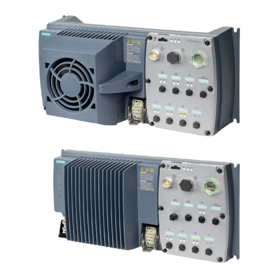
Installation 4.2 Electrical Installation ⑦ ⑭ Digital outputs 0 and 1 with status LED Motor, brake and temperature sensor con- nections Figure 4-4 Interfaces on the converter variants NOTICE Material damage from inappropriate supply system V > 1% Operating the converter on an inappropriate supply system can cause damage to the converter and other loads. -
Page 40: Protective Conductor
Installation 4.2 Electrical Installation TT system In a TT line system, the transformer grounding and the installation grounding are independent of one another. There are TT line supplies where the neutral conductor N is either transferred – or not. Operation of the inverter on the TN and TT line system The inverter is designed for TN and TT line systems with a grounded neutral point Above an installation altitude of 2000 m, the permissible line supplies are restricted. - Page 41 Installation 4.2 Electrical Installation Dimensioning the protective conductor Observe the local regulations for protective conductors subject to an increased leakage current at the installation site. ① Protective conductor for line feeder cables ② Protective conductor for inverter line feeder cables ③...
-
Page 42: Grounding Converter And Motor
Installation 4.2 Electrical Installation ① Additional requirements placed on the protective conductor ● For permanent connection, the protective conductor must fulfill at least one of the following conditions: – The protective conductor is routed so that it is protected against damage along its complete length. - Page 43 Installation 4.2 Electrical Installation • Connect the PE terminal on the left-hand side of the converter to the metal frame it is mounted on. • Recommended cable cross section: 10 mm² • Use a short wire connection preferably. • Clean the connection to the steel construction from paint or dirt.
-
Page 44: Basic Emc Rules
Installation 4.2 Electrical Installation Connection thread/length Clamping range Clamping Spanner Article No. without inlet range max/min width SW * D [mm] C [mm] max/min [mm] [mm] M25 x 1.5 20 … 13 16… 10 30 x 33 bg255mstri M32 x 1.5 25 …... -
Page 45: Connections And Interference Suppression
Installation 4.2 Electrical Installation ● In the case of both, the power cables and the signal and data cables, the cable shields should be connected by means of suitable EMC shield clips or via electrically conductive PG glands. These must connect the shields to the shield bonding options for cables and the unit housing respectively with excellent electrical conductivity and a large contact area. - Page 46 Grounding and high-frequency equipotential bonding measures in the drive system and in the plant You find further information on the rules for EMC compliant installation on the Internet: EMC design guidelines (http://support.automation.siemens.com/WW/view/en/60612658/0/en) Converter with the control units CU240D-2 Operating Instructions, 04/2018, FW V4.9 SP10, A5E34262100B AF...
-
Page 47: Branch Circuit Protection Of Individual Inverters
Installation 4.2 Electrical Installation 4.2.8 Branch circuit protection of individual inverters When you install a dedicated 400 V branch for each inverter, then you must individually fuse/protect each branch. Figure 4-8 Power supply to inverters through their own dedicated 400 V branch Branch circuit protection according to the IEC standard Table 4- 2 Branch circuit protection according to the IEC standard... - Page 48 DIVQ Type E combination motor controller (designation according to the UL standard - is NKJH available as SIEMENS circuit breaker) Table 4- 4 Branch circuit protection with non-semiconductor fuses of Classes J, T, CC, G or CF (UL Category JDDZ)
- Page 49 Installation 4.2 Electrical Installation Rated Power Module Fram Article No. UL cat. Max. rated Short circuit current power e size current of the rating SCCR circuit breaker 3RV2021-4AA… NKJH 16 A 65 kA, 480Y/277 V 3RV1031-4AA… or NKJH 16 A 65 kA, 480Y/277 V 3RV2031-4AA…...
-
Page 50: Branch Circuit Protection Of Multiple Inverters
Installation 4.2 Electrical Installation 4.2.9 Branch circuit protection of multiple inverters For installations with more than one inverter, the inverters are normally powered from a 400- V power bus with a T distributor. Figure 4-9 Power supply to an inverter group via a shared 400-V branch circuit Calculation of the branch circuit protection according to IEC and UL standards Calculation of the branch circuit protection: ●... - Page 51 Fuses of any manufacturer with faster tripping characteristic than class RK5, e.g. JDDZ class J, T, CC, G, or CF SIEMENS circuit breaker DIVQ Intrinsically safe SIEMENS circuit breaker NKJH Table 4- 8 Branch circuit protection with non-semiconductor fuses of Classes J, T, CC, G or CF (UL Category Code JDDZ) Max.
-
Page 52: 24-V Power Supply With Multiple Inverters
Installation 4.2 Electrical Installation 4.2.10 24-V power supply with multiple inverters Installation using 24 V bus The following options are available for the 24 V supply of the inverter: 1. A T distributor with integrated power supply unit supplies the 24 V. Advantage: Low installation costs. -
Page 53: Connections And Cables
Installation 4.2 Electrical Installation 4.2.11 Connections and cables Connectors "Switched" and "unswitched" 24 V power supply The unswitched 24 V power supply (1L+) is required for the device to function. ● Use a power supply with PELV (Protective Extra Low Voltage). ●... - Page 54 Installation 4.2 Electrical Installation Figure 4-11 CU240D-2 PROFIBUS connectors Converter with the control units CU240D-2 Operating Instructions, 04/2018, FW V4.9 SP10, A5E34262100B AF...
- Page 55 Installation 4.2 Electrical Installation Figure 4-12 CU240D-2 PROFINET connectors Converter with the control units CU240D-2 Operating Instructions, 04/2018, FW V4.9 SP10, A5E34262100B AF...
- Page 56 Installation 4.2 Electrical Installation Figure 4-13 CU240D-2 PROFINET Push-Pull connectors Converter with the control units CU240D-2 Operating Instructions, 04/2018, FW V4.9 SP10, A5E34262100B AF...
- Page 57 Installation 4.2 Electrical Installation Figure 4-14 CU240D-2 PROFINET FO connectors Converter with the control units CU240D-2 Operating Instructions, 04/2018, FW V4.9 SP10, A5E34262100B AF...
- Page 58 Installation 4.2 Electrical Installation WARNING Electric shock by live parts in the motor terminal box Hazardous voltage can be present on the pins for temperature sensor and motor holding brake. Touching live parts on the motor cable and in the motor terminal box can lead to death due electrical shock.
- Page 59 Installation 4.2 Electrical Installation Cable, connectors and tools specifications The detailed specifications for the cables, connectors and tools required to manufacture the necessary cables for the SINAMICS G120D are listed in the following tables. The connections that are detailed in this section relate to the physical connections that exist on the Inverter.
- Page 60 Installation 4.2 Electrical Installation Knorrtec (http://www.knorrtec.de/index.php/en/company-profile/siemens-solution- partner) Table 4- 12 Push-Pull variant PROFINET and 24 V DC connectors Connector Article number 24 V DC power supply 6GK1907-0AB10-6AA0 RJ45 PROFINET 6GK1901-1BB10-6AA0 Table 4- 13 Fibre optic connectors Connector Article number IE SC RJ POF PLUG PRO...
-
Page 61: Fieldbus Interfaces
Installation 4.2 Electrical Installation Cable Screening Max. length Analog input Screened 30 m (98 ft) Encoder Screened 30 m (98 ft) The motor, temperature sensor and motor holding brake are connected through a hybrid cable to the inverter using a Harting connector. 4.2.12 Fieldbus interfaces Fieldbus interfaces of the Control Units... - Page 62 Installation 4.2 Electrical Installation Operating the motor in a star connection In a star connection, the motor can provide its rated torque M in the range 0 … rated fre- quency f Rated voltage U = 400 V is available at a rated frequency f = 50 Hz.
-
Page 63: Connecting The Motor Holding Brake
Installation 4.2 Electrical Installation 4.2.14 Connecting the motor holding brake WARNING Electric shock from live parts in the motor terminal box The temperature sensor and motor holding brake connections of the converter are at DC link negative potential. Touching live parts on the motor cable and in the motor terminal box can result in death or severe injury. -
Page 64: Factory Settings Of The Inputs And Outputs
Installation 4.2 Electrical Installation The converter reduces high-frequency radiation of the motor holding brake with an internal interference suppressor. No other RC elements, varistors or freewheeling diodes are needed. 4.2.15 Factory settings of the inputs and outputs Factory settings of the inputs and outputs of the control unit CU240D-2 In the factory settings, the fieldbus interface of the inverter is not active. -
Page 65: Default Settings Of Inputs And Outputs
Installation 4.2 Electrical Installation 4.2.16 Default settings of inputs and outputs Default setting 1: "Conveyor system with 2 fixed frequencies" DO 0: p0730, DO 1: p0731 DI 0: r0722.0, …, DI 5: r0722.5 Fixed speed setpoint 3: p1003, fixed speed setpoint 4: p1004, fixed speed setpoint active: r1024 Speed setpoint (main setpoint): p1070[0] = 1024 DI 4 and DI 5 = high: the inverter adds the two fixed speed setpoints Default setting 2: "Conveyor system with Basic Safety"... - Page 66 Installation 4.2 Electrical Installation Default setting 3: "Conveyor system with 4 fixed frequencies" DO 0: p0730, DO 1: p0731 DI 0: r0722.0, …, DI 5: r0722.5 Fixed speed setpoint 1: p1001, … fixed speed setpoint 4: p1004, fixed speed setpoint active: r1024 Speed setpoint (main setpoint): p1070[0] = 1024 Several of the DI 0, DI 1, DI 4, and DI 5 = high: the inverter adds the corresponding fixed speed set- points.
- Page 67 Installation 4.2 Electrical Installation Default setting 5: "Conveyor system with fieldbus and Basic Safety" DO 0: p0730, DO 1: p0731 DI 4: r0722.4, DI 5: r0722.5 Speed setpoint (main setpoint): p1070[0] = 2050[1] Default setting 6: "Fieldbus with Extended Safety" DO 0: p0730, DO 1: p0731 DI 0: r0722.0, …, DI 5: r0722.5 Speed setpoint (main setpoint): p1070[0] = 2050[1]...
- Page 68 Installation 4.2 Electrical Installation Default setting 7: "Fieldbus with data set switchover" DO 0: p0730, DO 1: p0731 DI 0: r0722.0, …, DI 3: r0722.3 Speed setpoint (main setpoint): p1070[0] = 2050[1] Jog 1 speed setpoint: p1058, factory setting: 150 rpm Jog 2 speed setpoint: p1059, factory setting: -150 rpm Converter with the control units CU240D-2 Operating Instructions, 04/2018, FW V4.9 SP10, A5E34262100B AF...
- Page 69 Installation 4.2 Electrical Installation Default setting 8: "MOP with Basic Safety" DO 0: p0730, DO 1: p0731 DI 0: r0722.0, …, DI 5: r0722.5 Motorized potentiometer, setpoint after the ramp-function generator r1050 Speed setpoint (main setpoint): p1070[0] = 1050 Default setting 9: "Standard I/O with MOP" DO 0: p0730, DO 1: p0731 DI 0: r0722.0, …, DI 3: r0722.3 Motorized potentiometer, setpoint after the ramp-function generator r1050...
- Page 70 Installation 4.2 Electrical Installation Default setting 12: "Standard I/O with analog setpoint" DO 0: p0730, DO 1: p0731 DI 0: r0722.0, …, DI 2: r0722.2 AI 0: r0755[0] Speed setpoint (main setpoint): p1070[0] = 755[0] Default setting 13: "Standard I/O with analog setpoint and safety" DO 0: p0730, DO 1: p0731 DI 0: r0722.0, …, DI 5: r0722.5 AI 0: r0755[0]...
- Page 71 Installation 4.2 Electrical Installation Default setting 14: "Process industry with fieldbus" DO 0: p0730, DO 1: p0731 DI 0: r0722.0, …, DI 5: r0722.5 Motorized potentiometer, setpoint after the ramp-function generator r1050 Speed setpoint (main setpoint): p1070[0] = 2050[1], p1070[1] = 1050 Switch controller via PZD01, bit 15: p0810 = r2090.15 Converter with the control units CU240D-2 Operating Instructions, 04/2018, FW V4.9 SP10, A5E34262100B AF...
- Page 72 Installation 4.2 Electrical Installation Default setting 24: "Distributed conveyor systems with fieldbus" DO 0: p0730, DO 1: p0731 DI 0: r0722.0, …, DI 5: r0722.5 p2081[0] = r0722.0, …, p2081[5] = r0722.5 p0730 = r2094.0, p0731 = r2094.1 Speed setpoint (main setpoint): p1070[0] = 2050[1] Converter with the control units CU240D-2 Operating Instructions, 04/2018, FW V4.9 SP10, A5E34262100B AF...
-
Page 73: Fail-Safe Digital Input
Installation 4.2 Electrical Installation Default setting 25: "Distributed conveyor systems with fieldbus, safety" DO 0: p0730, DO 1: p0731 DI 0: r0722.0, …, DI 5: r0722.5 p2081[0] = r0722.0, …, p2081[3] = r0722.3 p0730 = r2094.0, p0731 = r2094.1 Speed setpoint (main setpoint): p1070[0] = 2050[1] 4.2.17 Fail-safe digital input To enable a safety function via the terminal strip of the inverter, you need a fail-safe digital... -
Page 74: Connecting The Inverter To Profinet
Installation 4.3 Connecting the inverter to PROFINET Connect safe P/P-switching outputs You may not connect safe P/P-switching outputs to a safe input. PP-switching output Fault detection The inverter compares the two signals of the fail-safe digital input. The inverter thus detects, for example the following faults: ●... - Page 75 ● Shared Device for Control Units with fail-safe functions The inverter as Ethernet node Figure 4-19 The inverter as Ethernet node See also http://support.automation.siemens.com/WW/view/de/19292127 (http://support.automation.siemens.com/WW/view/en/19292127) PROFINET – the Ethernet standard for automation (http://w3.siemens.com/mcms/automation/en/industrial- communications/profinet/Pages/Default.aspx) Converter with the control units CU240D-2...
-
Page 76: Connecting The Profinet Interface
"Fieldbuses". Overview of the manuals (Page 343) Further information on PROFINET Further information on PROFINET can be found on the Internet: ● PROFINET – the Ethernet standard for automation (http://w3.siemens.com/mcms/automation/en/industrial- communications/profinet/Pages/Default.aspx) ● PROFINET system description (https://support.industry.siemens.com/cs/ww/en/view/19292127) 4.3.1 Connecting the PROFINET interface Industrial Ethernet Cables and cable length Listed in the table below are the recommended Ethernet cables. - Page 77 Controlling the speed of a SINAMICS G110M/G120/G120C/G120D with S7-300/400F via PROFINET or PROFIBUS, with Safety Integrated (via terminal) and HMI (https://support.industry.siemens.com/cs/ww/en/view/60441457) Controlling the speed of a SINAMICS G110M / G120 (Startdrive) with S7-1500 (TO) via PROFINET or PROFIBUS, with Safety Integrated (via terminal) and HMI (https://support.industry.siemens.com/cs/ww/en/view/78788716)
-
Page 78: Installing Gsdml
Insert a memory card into the inverter. Set p0804 = 12. The inverter writes the GSDML as zipped file (*.zip) into directory /SIEMENS/SINAMICS/DATA/CFG on the memory card. 2. Unzip the GSDML file on your computer. 3. Import the GSDML into the engineering system of the controller. -
Page 79: What Do You Have To Set For Communication Via Profibus
Controlling the speed of a SINAMICS G110M/G120/G120C/G120D with S7-300/400F via PROFINET or PROFIBUS, with Safety Integrated (via terminal) and HMI (https://support.industry.siemens.com/cs/ww/en/view/60441457) Controlling the speed of a SINAMICS G110M / G120 (Startdrive) with S7-1500 (TO) via PROFINET or PROFIBUS, with Safety Integrated (via terminal) and HMI (https://support.industry.siemens.com/cs/ww/en/view/78788716) -
Page 80: Installing The Gsd
Insert a memory card into the inverter. Set p0804 to 12. The inverter writes the GSD as zipped file (*.zip) into directory /SIEMENS/SINAMICS/DATA/CFG on the memory card. 2. Unzip the GSD file on your computer. 3. Import the GSD in the engineering system of the controller. - Page 81 Installation 4.4 Connecting the inverter to PROFIBUS If you are working with Startdrive, back up the settings so they are not lost if the power fails. Overview of the interfaces (Page 36) Setting the bus address Procedure 1. Set the address using one of the subsequently listed options: –...
- Page 82 Installation 4.4 Connecting the inverter to PROFIBUS Converter with the control units CU240D-2 Operating Instructions, 04/2018, FW V4.9 SP10, A5E34262100B AF...
-
Page 83: Commissioning
Commissioning Commissioning tools Figure 5-1 Commissioning tools - PC or IOP-2 Handheld Kit IOP-2 Handheld: Article number 6SL3255-0AA00-4HA1 Converter with the control units CU240D-2 Operating Instructions, 04/2018, FW V4.9 SP10, A5E34262100B AF... - Page 84 ● Startdrive: Article number 6SL3072-4CA02-1XG0 STARTER and Startdrive download: ● STARTER (http://support.automation.siemens.com/WW/view/en/10804985/133200) ● Startdrive (http://support.automation.siemens.com/WW/view/en/68034568) Help regarding operation: ● STARTER videos (http://www.automation.siemens.com/mcms/mc-drives/en/low-voltage- inverter/sinamics-g120/videos/Pages/videos.aspx) ● Startdrive tutorial (http://support.automation.siemens.com/WW/view/en/73598459) Converter with the control units CU240D-2 Operating Instructions, 04/2018, FW V4.9 SP10, A5E34262100B AF...
-
Page 85: Commissioning Guidelines
Commissioning 5.2 Commissioning guidelines Commissioning guidelines Overview 1. Define the requirements to be met by the drive for your application. (Page 84) 2. Restore the factory settings of the inverter if necessary. (Page 97) 3. Check if the factory setting of the inverter is sufficient for your application. -
Page 86: Preparing For Commissioning
Commissioning 5.3 Preparing for commissioning Preparing for commissioning Data for a standard induction motor Before starting commissioning, you must know the following data: ● Which motor is connected to the inverter? Note down the Article No. of the motor and the motor’s nameplate data. If available, note down the motor code on the motor’s nameplate. - Page 87 Commissioning 5.3 Preparing for commissioning Factory settings of the inputs and outputs (Page 62) Switching the motor on and off Figure 5-3 Switching on and switching off the motor and reversing in the factory setting The inverter is set in the factory as follows: ●...
- Page 88 Commissioning 5.3 Preparing for commissioning Minimum and maximum speed ● Minimum speed - factory setting 0 [rpm] The minimum speed is the lowest speed of the motor independent of the speed setpoint. A minimum speed is, for example, useful for fans or pumps. ●...
-
Page 89: Selecting The Control Mode
Commissioning 5.3 Preparing for commissioning 5.3.2 Selecting the control mode Suitable applications and typical control properties U/f control or FCC (flux current con- Vector control without an encod- Vector control with encoder trol) without an encoder Application Horizontal conveyor technology Horizontal conveyor technol- Vertical conveyor technolo- •... -
Page 90: Quick Commissioning With The Iop-2
Commissioning 5.4 Quick commissioning with the IOP-2 Quick commissioning with the IOP-2 Commissioning a 1FK7 encoderless synchronous motor If you want to operate the inverter using a 1FK7 encoderless synchronous motor, we recommend using the PC tools Startdrive or STARTER for commissioning. Overview To perform the basic commissioning of a decentralized drive it is necessary to use the IOP-2 Handheld Kit (HHK). - Page 91 Commissioning 5.4 Quick commissioning with the IOP-2 Select Continue Select Control Mode Select Motor Data Select Enter Motor Data Select Motor Type Select Characteristic Select Continue Input Motor Frequency Input Motor Voltage Input Motor Current Input Power Rating Input Motor Speed Converter with the control units CU240D-2 Operating Instructions, 04/2018, FW V4.9 SP10, A5E34262100B AF...
- Page 92 Commissioning 5.4 Quick commissioning with the IOP-2 Select Technology Applica- Select required Motor Data Select Macro Source tion ID function Input the Motor Speed Input Current Limit Select Motor Data ID option Input Encoder Type Input Encoder Pulses per rev Select Macro Source Input Maximum Speed Input Ramp-up time...
-
Page 93: Quick Commissioning With A Pc
Commissioning 5.5 Quick commissioning with a PC Select Motor Temperature Select Motor Holding Brake Input Minimum Motor Spped Sensor option Summary of settings - Select Save Settings Settings saved Continue Status Screen displayed On first ON command - Motor ID is performed Quick commissioning with a PC The screen forms that are shown in this manual show generally valid examples. -
Page 94: Creating A Project
Commissioning 5.5 Quick commissioning with a PC 5.5.1 Creating a project Creating a new project Procedure 1. Start the Startdrive commissioning software. 2. In the menu, select "Project" → "New…". 3. Specify a name of your choice for the project. You have created a new project. -
Page 95: Carrying Out Quick Commissioning
Commissioning 5.5 Quick commissioning with a PC 5. When the USB interface is appropriately set, then the "Accessible nodes" screen form shows the inverters that can be accessed. If you have not correctly set the USB interface, then the following "No additional nodes found"... - Page 96 Commissioning 5.5 Quick commissioning with a PC Selecting the control mode (Page 87) Select the I/O configuration to preassign the inverter interfaces. Default settings of inputs and outputs (Page 63) Set the applicable motor standard and the inverter supply voltage. Select the application for the inverter: ●...
-
Page 97: Adapting The Encoder Data
Commissioning 5.5 Quick commissioning with a PC You have entered all of the data that is necessary for the quick commissioning of your inverter. ❒ 5.5.4 Adapting the encoder data Preconditions ● You have selected an encoder type that does not precisely match your encoder, because it is not included in the list of default encoder types. - Page 98 Commissioning 5.5 Quick commissioning with a PC To start the motor data identification routine, you must switch on the motor. Identifying the motor data and optimizing the closed-loop control Preconditions ● You have selected a method of motor data identification during quick commissioning, e.g. measurement of the motor data while the motor is stationary.
-
Page 99: Restoring The Factory Setting
Commissioning 5.6 Restoring the factory setting 4. Switch on the motor. The inverter starts the motor data identification. This measurement can take several minutes. Depending on the setting, after motor data identification has been completed, the inverter switches off the motor - or it accelerates it to the currently set setpoint. 5. -
Page 100: Resetting The Safety Functions To The Factory Setting
Commissioning 5.6 Restoring the factory setting The settings of the safety functions are protected by a password. Settings that are not changed when restoring the factory setting The communication settings and the settings of the motor standard (IEC/NEMA) are kept when restoring the factory setting. -
Page 101: Restore The Settings To The Factory Settings (Without Safety Functions)
Commissioning 5.6 Restoring the factory setting Procedure with an operator panel 1. Set p0010 = 30 Activate reset settings. 2. p9761 = … Enter the password for the safety functions 3. Start the reset with p0970 = 5. 4. Wait until the inverter sets p0970 = 0. 5. - Page 102 Commissioning 5.6 Restoring the factory setting You have reset the inverter to the factory settings. ❒ Procedure with operator panel Proceed as follows to reset the inverter to factory settings: 1. Select the "Extras" menu 2. Select the "Parameter settings" menu 3.
-
Page 103: Advanced Commissioning
Advanced commissioning Overview of the converter functions Figure 6-1 Overview of inverter functions Drive control The inverter receives its commands from the higher-level control via the terminal strip or the fieldbus interface of the Control Unit. The drive control defines how the inverter responds to the commands. - Page 104 Advanced commissioning 6.1 Overview of the converter functions The free function blocks permit configurable signal processing within the inverter. Free function blocks (Page 145) You can select in which physical units the inverter represents its associated values. Selecting physical units (Page 146) Safety functions The safety functions fulfill increased requirements regarding the functional safety of the drive.
- Page 105 Advanced commissioning 6.1 Overview of the converter functions Overcurrent protection (Page 220) Inverter protection using temperature monitoring (Page 221) Motor temperature monitoring using a temperature sensor (Page 224) Motor protection by calculating the temperature (Page 228) The monitoring of the driven load prevents impermissible operating modes, e.g. dry-running of a pump.
-
Page 106: Sequence Control When Switching The Motor On And Off
Advanced commissioning 6.2 Sequence control when switching the motor on and off Sequence control when switching the motor on and off Overview The sequence control defines the rules for switching the motor on and off. Figure 6-2 Simplified representation of the sequence control After switching the supply voltage on, the inverter normally goes into the "ready to start"... -
Page 107: Function Description
Advanced commissioning 6.2 Sequence control when switching the motor on and off Function description Figure 6-3 Sequence control of the inverter when the motor is switched on and off Inverter states S1 … S5c are defined in the PROFIdrive profile. The sequence control defines the transition from one state to another. -
Page 108: Adapt The Default Setting Of The Terminal Strip
Advanced commissioning 6.3 Adapt the default setting of the terminal strip Table 6- 2 Commands for switching the motor on and off The inverter switches the motor on. Jogging 1 Jogging 2 Enable operation OFF1, OFF3 The inverter brakes the motor. The inverter switches off the motor once it comes to a standstill. The motor is considered to be stationary if the speed is less than a defined minimum speed. - Page 109 Advanced commissioning 6.3 Adapt the default setting of the terminal strip Figure 6-4 Internal interconnection of the inputs and outputs Converter with the control units CU240D-2 Operating Instructions, 04/2018, FW V4.9 SP10, A5E34262100B AF...
-
Page 110: Digital Inputs
Advanced commissioning 6.3 Adapt the default setting of the terminal strip 6.3.1 Digital inputs Changing the function of a digital input Interconnect the status parameter of the digital input with a binector input of your choice. Binector inputs are marked with "BI" in the parameter list of the List Manual. -
Page 111: Fail-Safe Digital Input
Advanced commissioning 6.3 Adapt the default setting of the terminal strip Advanced settings You can debounce the digital input signal using parameter p0724. For more information, see the parameter list and the function block diagrams 2210 ff of the List Manual. Analog inputs as digital inputs When required, you can use the analog inputs as additional digital inputs. -
Page 112: Digital Outputs
Advanced commissioning 6.3 Adapt the default setting of the terminal strip 6.3.3 Digital outputs Changing the function of a digital output Interconnect the digital output with a binector output of your choice. Binector outputs are marked with "BO" in the parameter list of the List Manual. Table 6- 4 Binector outputs of the inverter (selection) Deactivating digital output... -
Page 113: Analog Inputs
Advanced commissioning 6.3 Adapt the default setting of the terminal strip 6.3.4 Analog inputs Overview Changing the function of the analog input 1. Define the analog input type using parameter p0756 to voltage input 0 V … 10 V. 2. Specify the function of the analog input by interconnecting parameter p0755 with a connector input CI of your choice. - Page 114 Advanced commissioning 6.3 Adapt the default setting of the terminal strip Table 6- 5 Parameters for the scaling characteristic and wire break monitoring Parameter Description p0757 x-coordinate of 1st characteristic point [V] p0758 y coordinate of the 1st characteristic point [% of p200x] p200x are the parameters of the reference variables, e.g.
-
Page 115: Drive Control Via Profibus Or Profinet
Advanced commissioning 6.4 Drive control via PROFIBUS or PROFINET Figure 6-6 Deadband of the analog input p0764[0] Analog inputs dead zone, AI 0 (factory setting: 0) p0764[1] Analog inputs dead zone, AI 1 (factory setting: 0) Using an analog input as digital input An analog input can also be used as digital input. -
Page 116: Telegrams
Advanced commissioning 6.4 Drive control via PROFIBUS or PROFINET Figure 6-8 Telegram structure Every telegram for cyclic data exchange has the following basic structure: ● Header and trailer form the protocol frame. ● User data is located within the frame: –... - Page 117 Advanced commissioning 6.4 Drive control via PROFIBUS or PROFINET 16-bit speed setpoint with torque limiting 16-bit speed setpoint for PCS7 16-bit speed setpoint with reading and writing to parameters 16-bit speed setpoint for PCS7 with reading and writing to parameters Unassigned interconnection and length Table 6- 7 Explanation of the abbreviations...
- Page 118 Advanced commissioning 6.4 Drive control via PROFIBUS or PROFINET Abbreviation Explanation Abbreviation Explanation NIST_A_GLATT Smoothed actual speed WARN_CODE Alarm code value IAIST_GLATT Smoothed current actual MELD_NAMUR Message according to the VIK- value NAMUR definition Interconnection of the process data Figure 6-9 Interconnection of the send data In the inverter, the send data are available in the "Word"...
-
Page 119: Control And Status Word 1
Advanced commissioning 6.4 Drive control via PROFIBUS or PROFINET telegram, then the inverter automatically interconnects parameters r2050, r2060 and r2090 …r2093 with the appropriate signals. If you wish to adapt a predefined telegram, then you must interconnect the send and receive data with the appropriate signals. - Page 120 Advanced commissioning 6.4 Drive control via PROFIBUS or PROFINET Significance Explanation Signal inter- connection Telegram 20 All other tele- in the in- grams verter 1 = Enable setpoint Motor accelerates with the ramp-up time p1120 to the setpoint. 0 → 1 = Acknowledge faults Acknowledge fault.
- Page 121 Advanced commissioning 6.4 Drive control via PROFIBUS or PROFINET Significance Remarks Signal inter- connection Telegram 20 All other tele- in the in- grams verter 1 = Alarm active Motor remains switched on; no acknowl- p2080[7] = edgement is necessary. r2139.7 1 = Speed deviation within the Setpoint / actual value deviation within the p2080[8] =...
-
Page 122: Control And Status Word 3
Advanced commissioning 6.4 Drive control via PROFIBUS or PROFINET 6.4.4 Control and status word 3 Control word 3 (STW3) Bit Meaning Explanation Signal interconnection in the inverter Telegram 350 1 = fixed setpoint bit 0 Selects up to 16 different fixed p1020[0] = r2093.0 setpoints. - Page 123 Advanced commissioning 6.4 Drive control via PROFIBUS or PROFINET Status word 3 (ZSW3) Meaning Description Signal intercon- nection in the inverter 1 = DC braking active p2051[3] = r0053 1 = |n_act | > p1226 Absolute current speed > stationary state detection 1 = |n_act | >...
-
Page 124: Namur Message Word
Advanced commissioning 6.4 Drive control via PROFIBUS or PROFINET 6.4.5 NAMUR message word Fault word according to the VIK-NAMUR definition (MELD_NAMUR) Table 6- 8 Fault word according to the VIK-NAMUR definition and interconnection with parameters in the inverter Bit Significance P no. -
Page 125: Parameter Channel
Advanced commissioning 6.4 Drive control via PROFIBUS or PROFINET 6.4.6 Parameter channel Structure of the parameter channel The parameter channel consists of four words. The 1st and 2nd words transfer the parameter number, index and the type of task (read or write). The 3rd and 4th words contain the parameter content. - Page 126 Advanced commissioning 6.4 Drive control via PROFIBUS or PROFINET Table 6- 10 Response identifiers, inverter → control Description No response Transfer parameter value (word) Transfer parameter value (double word) Transfer descriptive element Transfer parameter value (field, word) Transfer parameter value (field, double word) Transfer number of field elements Inverter cannot process the request.
- Page 127 Advanced commissioning 6.4 Drive control via PROFIBUS or PROFINET Description 86 hex Write access only for commissioning (p0010 = 15) (operating state of the inverter prevents a parameter change) 87 hex Know-how protection active, access locked C8 hex Change request below the currently valid limit (change request to a value that lies within the "absolute"...
- Page 128 Advanced commissioning 6.4 Drive control via PROFIBUS or PROFINET PWE: Parameter value or connector Parameter values or connectors can be located in the PWE. Table 6- 12 Parameter value or connector PWE 1 PWE 2 Parameter value Bit 15 … 0 Bit 15 …...
-
Page 129: Examples For Using The Parameter Channel
Advanced commissioning 6.4 Drive control via PROFIBUS or PROFINET 6.4.7 Examples for using the parameter channel Read request: Read out serial number of the Power Module (p7841[2]) To obtain the value of the indexed parameter p7841, you must fill the telegram of the parameter channel with the following data: ●... - Page 130 Advanced commissioning 6.4 Drive control via PROFIBUS or PROFINET Write request: Assign digital input 2 with the function ON/OFF1 (p0840[1] = 722.2) In order to link digital input 2 with ON/OFF1, you must assign parameter p0840[1] (source, ON/OFF1) the value 722.2 (DI 2). To do this, you must populate the telegram of the parameter channel as follows: ●...
-
Page 131: Extending The Telegram
Advanced commissioning 6.4 Drive control via PROFIBUS or PROFINET 6.4.8 Extending the telegram Overview When you have selected a telegram, the inverter interconnects the corresponding signals with the fieldbus interface. Generally, these interconnections are locked so that they cannot be changed. However, with the appropriate setting in the inverter, the telegram can be extended or even freely interconnected. - Page 132 Standard telegram 1, PZD-2/2 Standard telegram 20, PZD-2/6 350: SIEMENS telegram 350, PZD-4/4 352: SIEMENS telegram 352, PZD-6/6 353: SIEMENS telegram 353, PZD-2/2, PKW-4/4 354: SIEMENS telegram 354, PZD-6/6, PKW-4/4 999: Free telegram configuring r2050[0…11] PROFIdrive PZD receive word Received PZD (setpoints) in the word format p2051[0…16] PROFIdrive PZD send word...
-
Page 133: Slave-To-Slave Communication
Further information about acyclic communication is provided in the Fieldbus function manual. Overview of the manuals (Page 343) Application example, "Read and write to parameters" Further information is provided on the Internet: Application examples (https://support.industry.siemens.com/cs/ww/en/view/29157692) Converter with the control units CU240D-2 Operating Instructions, 04/2018, FW V4.9 SP10, A5E34262100B AF... -
Page 134: Jogging
Advanced commissioning 6.5 Jogging Jogging The "Jog" function is typically used to temporarily move a machine part using local control commands, e.g. a transport conveyor belt. Commands "Jog 1" or "Jog: 2" switch the motor on and off. The commands are only active when the inverter is in the "Ready for switching on" state. Figure 6-14 Behavior of the motor when "jogging"... - Page 135 Advanced commissioning 6.5 Jogging Jog settings Parameter Description p1058 Jogging 1 speed setpoint (factory setting 150 rpm) p1059 Jogging 2 speed setpoint (factory setting -150 rpm) p1082 Maximum speed (factory setting 1500 rpm) p1110 Inhibit negative direction =0: Negative direction of rotation is enabled =1: Negative direction of rotation is inhibited p1111 Inhibit positive direction...
-
Page 136: Limit Position Control
Advanced commissioning 6.6 Limit position control Limit position control Limit position and limit switch A limit position is a position in the direction of motion of a machine component at which the motion stops due to the construction. A limit switch is a sensor that signals that the limit position has been reached. - Page 137 Advanced commissioning 6.6 Limit position control ① The motor moves the machine component in the direction of the positive limit position. ② The positive limit position has been reached. The motor stops with the OFF3 ramp-down time. ③ The motor moves the machine component in the opposite direction at a 0 → 1 signal change. ④...
- Page 138 Advanced commissioning 6.6 Limit position control Application example: Roller conveyor with rotary table A rotary table in a roller conveyor directs the material at the crossing of two con- veyor lines. The rotary table rotates through 90° from one limit position to the other.
- Page 139 Advanced commissioning 6.6 Limit position control 4. Specify a speed setpoint. We recommended that you use a fixed setpoint for the limit position control. Fixed speed setpoint as setpoint source (Page 172). 5. Start the rotary table briefly. 6. If the rotary table has not traversed in the direction of the opposite limit position, invert the speed setpoint in the inverter.
-
Page 140: Switching Over The Drive Control (Command Data Set)
Advanced commissioning 6.7 Switching over the drive control (command data set) Switching over the drive control (command data set) Several applications require the option of switching over the control authority to operate the inverter. Example: The motor is to be operable either from a central control via the fieldbus or via the local digital inputs of the inverter. - Page 141 Advanced commissioning 6.7 Switching over the drive control (command data set) An overview of all the parameters that belong to the command data sets is provided in the List Manual. Note The converter requires approx. 4 ms to switch over the command data set. Changing the number of command data sets Procedure 1.
- Page 142 Advanced commissioning 6.7 Switching over the drive control (command data set) Parameter Description p0810 Command data set selection CDS bit 0 p0811 Command data set selection CDS bit 1 Converter with the control units CU240D-2 Operating Instructions, 04/2018, FW V4.9 SP10, A5E34262100B AF...
-
Page 143: Motor Holding Brake
Advanced commissioning 6.8 Motor holding brake Motor holding brake The motor holding brake holds the motor in position when it is switched off. When the "Motor holding brake" function is correctly set, the motor remains switched on as long as the motor holding brake is open. The inverter only switches the motor off when the motor holding brake is closed. - Page 144 Advanced commissioning 6.8 Motor holding brake 3. When the first of the two times (p1227 or p1228) has elapsed, the inverter issues the command to close the brake. 4. After the "motor holding brake closing time" p1217, the inverter switches off the motor. The motor holding brake must close within the time p1217.
- Page 145 Advanced commissioning 6.8 Motor holding brake Commissioning a motor holding brake Precondition The motor holding brake is connected to the inverter. WARNING Load can fall if the "Motor holding brake" function is incorrectly set For applications with a suspended load, such as cranes and elevators, there is a danger to life if the "Motor holding brake"...
- Page 146 Advanced commissioning 6.8 Motor holding brake 6. Check the acceleration behavior of the drive immediately after the motor has been switched on: – If the motor holding brake opens too late, the inverter will accelerate the motor suddenly against the closed motor holding brake. Set p1216 larger.
-
Page 147: Free Function Blocks
Advanced commissioning 6.9 Free function blocks Table 6- 14 Advanced settings Parameter Description p0346 Magnetizing time (factory setting 0 s) During this time the induction motor is magnetized. The inverter calculates this pa- rameter using p0340 = 1 or 3. p0855 Open motor holding brake (imperative) (factory setting 0) p0858... -
Page 148: Further Information
Advanced commissioning 6.10 Selecting physical units 6.9.2 Further information Application description for the free function blocks Further information is provided on the Internet: FAQ (http://support.automation.siemens.com/WW/view/en/85168215) 6.10 Selecting physical units 6.10.1 Motor standard Selection options and parameters involved The inverter represents the motor data corresponding to motor standard IEC or NEMA in different system units: SI units or US units. - Page 149 Advanced commissioning 6.10 Selecting physical units Options when selecting the system of units The following options apply when selecting the system of units: ● p0505 = 1: System of units SI (factory setting) Torque [Nm], power [kW], temperature [°C or K] ●...
-
Page 150: Technological Unit Of The Technology Controller
Advanced commissioning 6.10 Selecting physical units An overview of the unit groups and the possible physical units can also be found in the List Manual. See also Overview of the manuals (Page 343) 6.10.3 Technological unit of the technology controller Options when selecting the technological unit p0595 defines in which technological unit the input and output variables of the technology controller are calculated, e.g. -
Page 151: Safe Torque Off (Sto) Safety Function
Advanced commissioning 6.11 Safe Torque Off (STO) safety function Procedure 1. In the project, select "Parameter". 2. Select "Units". 3. Select the system of units. 4. Select the technological unit of the technology controller. 5. Save your settings. 6. Go online. The inverter signals that offline, other units and process variables are set than in the inverter itself. -
Page 152: Function Description
Advanced commissioning 6.11 Safe Torque Off (STO) safety function 6.11.1 Function description What does the STO safety function do? An inverter with active STO function prevents energy supply to the motor. The motor can no longer generate torque at the motor shaft. Consequently, the STO function prevents the starting of an electrically-driven machine component. - Page 153 Advanced commissioning 6.11 Safe Torque Off (STO) safety function The STO function is suitable for achieving an emergency stop but not an emergency off. Risk: Risk of electric shock: Risk of unexpected motion: Measure to minimize Safe switch off Safely stop and safely prevent re- risk: starting Switching off the electric power sup-...
-
Page 154: Precondition For Using Sto
Advanced commissioning 6.11 Safe Torque Off (STO) safety function Application examples for the STO function The STO function is suitable for applications where the motor is already at a standstill or will come to a standstill in a short, safe period of time through friction. STO does not shorten the run-on of machine components with high inertia. - Page 155 Advanced commissioning 6.11 Safe Torque Off (STO) safety function The probabilities of failure (PFH) and certification of the safety functions also apply without password. What do I do if I lose the password? Requirement You have forgotten the password, however, you would nevertheless like to change the setting of the safety functions.
-
Page 156: Configuring A Safety Function
Advanced commissioning 6.11 Safe Torque Off (STO) safety function 6.11.3.3 Configuring a safety function Procedure 1. Select "Select safety functionality". 2. Select "Basic Functions". 3. Select "Control type/safety functions". 4. Select "Via terminals" as control type for the safety functions. You have configured the safety functions. -
Page 157: Interconnecting The "Sto Active" Signal
Advanced commissioning 6.11 Safe Torque Off (STO) safety function Parameter Description 1 hex Basic functions via onboard terminals has been enabled p9761 Enter a password (factory setting: 0000 hex) Permissible passwords lie in the range 1 … FFFF FFFF. p9762 New password p9763 Password confirmation... -
Page 158: Setting The Filter For Fail-Safe Digital Inputs
Advanced commissioning 6.11 Safe Torque Off (STO) safety function 6.11.3.5 Setting the filter for fail-safe digital inputs Requirement You are online with Startdrive. Procedure 1. Navigate to the filter settings. 2. Set the debounce time for the F-DI input filter. 3. - Page 159 Advanced commissioning 6.11 Safe Torque Off (STO) safety function Figure 6-20 Simultaneity monitoring with discrepancy time Filter to suppress short signals In the following cases, an immediate inverter response to signal changes of the fail-safe digital inputs is not desirable: ●...
-
Page 160: Setting The Forced Checking Procedure (Test Stop)
Advanced commissioning 6.11 Safe Torque Off (STO) safety function Figure 6-22 Filter to suppress brief signals The filter extends the response time of the safety function by the debounce time. Parameter Description p9650 F-DI changeover tolerance time (factory setting: 500 ms) Tolerance time to change over the fail-safe digital input for the basic functions. - Page 161 Advanced commissioning 6.11 Safe Torque Off (STO) safety function You have set the forced checking procedure (test stop) for the Basic Functions. ❒ Description The forced checking procedure (test stop) of the basic functions is an inverter self test. The inverter checks its circuits to switch off the torque.
- Page 162 Advanced commissioning 6.11 Safe Torque Off (STO) safety function Procedure 1. Press the "End safety commissioning" button. 2. Confirm the prompt for saving your settings (copy RAM to ROM). 3. Disconnect the online connection. 4. Select the "Load from device (software)" button. 5.
- Page 163 Advanced commissioning 6.11 Safe Torque Off (STO) safety function If you control the safety functions in the inverter via failsafe digital inputs, then you must check as to whether the failsafe digital inputs are in some instances interconnected with a "standard"...
-
Page 164: Acceptance - Completion Of Commissioning
Advanced commissioning 6.11 Safe Torque Off (STO) safety function 6.11.3.7 Acceptance - completion of commissioning What is an acceptance? The machine manufacturer is responsible in ensuring that his plant or machine functions perfectly. As a consequence, after commissioning, the machine manufacturer must check those functions or have them checked by specialist personnel, which represent an increased risk of injury or material damage. -
Page 165: Reduced Acceptance Test After Function Expansions
– and generates an acceptance report as Excel file. Further information is provided on the Internet: Startdrive, system requirements and download (https://support.industry.siemens.com/cs/ww/en/view/109752254) 6.11.3.8 Reduced acceptance test after function expansions Reduced acceptance test after function expansions A full acceptance test is necessary only after first commissioning. - Page 166 Advanced commissioning 6.12 Setpoints Figure 6-24 Setpoint sources for the inverter You have the following options when selecting the source of the main setpoint: ● Inverter analog input. ● Inverter fieldbus interface. ● Motorized potentiometer simulated in the inverter. ● Fixed setpoints saved in the inverter. You have the same selection options when selecting the source of the supplementary setpoint.
-
Page 167: Analog Input As Setpoint Source
Advanced commissioning 6.12 Setpoints 6.12.2 Analog input as setpoint source Function description Figure 6-25 Example: Analog input 0 as setpoint source In the quick commissioning, you define the preassignment for the inverter interfaces. Depending on what has been preassigned, after quick commissioning, the analog input can be interconnected with the main setpoint. - Page 168 Advanced commissioning 6.12 Setpoints Further information For further information refer to the function diagrams 2250 ff and 3030 of the List Manual. See also Analog inputs (Page 111) Converter with the control units CU240D-2 Operating Instructions, 04/2018, FW V4.9 SP10, A5E34262100B AF...
-
Page 169: Specifying The Setpoint Via The Fieldbus
Advanced commissioning 6.12 Setpoints 6.12.3 Specifying the setpoint via the fieldbus Function description Figure 6-26 Fieldbus as setpoint source In the quick commissioning, you define the preassignment for the inverter interfaces. Depending on what has been preassigned, after quick commissioning, the receive word PZD02 can be interconnected with the main setpoint. - Page 170 Advanced commissioning 6.12 Setpoints Parameter Description Setting p1076[0…n] CI: Supplementary setpoint Signal source for scaling the supplementary setpoint scaling Factory setting: 0 r2050[0…11] CO: PROFIdrive PZD re- Connector output to interconnect the PZD received from the fieldbus ceive word controller in the word format. [1] Most standard telegrams receive the speed setpoint as receive word PZD02.
-
Page 171: Motorized Potentiometer As Setpoint Source
Advanced commissioning 6.12 Setpoints 6.12.4 Motorized potentiometer as setpoint source Function description The "Motorized potentiometer" function emulates an electromechanical potentiometer. The output value of the motorized potentiometer can be set with the "higher" and "lower" control signals. Figure 6-27 Motorized potentiometer as setpoint source Figure 6-28 Function chart of the motorized potentiometer Example... - Page 172 Advanced commissioning 6.12 Setpoints Parameter Table 6- 17 Basic setup of motorized potentiometer Parameter Description Setting p1035[0…n] BI: Motorized potentiometer Signal source to continuously increase the setpoint setpoint higher The factory setting depends on the inverter. Inverters with PROFIBUS or PROFINET interface: [0] 2090.13 [1] 0 Inverters without PROFIBUS or PROFINET interface: 0...
- Page 173 Advanced commissioning 6.12 Setpoints Table 6- 18 Extended setup of motorized potentiometer Parameter Description Setting p1030[0…n] Motorized potentiometer Configuration for the motorized potentiometer configuration Factory setting: 00110 bin Storage active = 0: After the motor has been switched on, the setpoint = p1040 = 1: After the motor has switched off, the inverter saves the setpoint.
-
Page 174: Fixed Speed Setpoint As Setpoint Source
Advanced commissioning 6.12 Setpoints 6.12.5 Fixed speed setpoint as setpoint source Function description Figure 6-29 Fixed speed setpoint as setpoint source The inverter makes a distinction between two methods when selecting the fixed speed setpoints: Directly selecting a fixed speed setpoint You set 4 different fixed speed setpoints. - Page 175 Advanced commissioning 6.12 Setpoints Figure 6-31 Binary selection of the fixed speed setpoint Example After it has been switched on, a conveyor belt only runs with two different velocities. The motor should now operate with the following corresponding speeds: ● The signal at digital input 0 switches the motor on and accelerates it up to 300 rpm. ●...
- Page 176 Advanced commissioning 6.12 Setpoints Parameter Parameter Description Setting p1001[0...n] Fixed speed setpoint 1 [rpm] Fixed speed setpoint 1 Factory setting: 0 rpm p1002[0...n] Fixed speed setpoint 2 [rpm] Fixed speed setpoint 2 Factory setting: 0 rpm p1015[0...n] Fixed speed setpoint 15 Fixed speed setpoint 15 [rpm] Factory setting: 0 rpm...
-
Page 177: Setpoint Calculation
Advanced commissioning 6.13 Setpoint calculation Table 6- 21 Settings for the application example Parameter Description p1001 = 300.000 Fixed speed setpoint 1 [rpm] p1002 = 2000.000 Fixed speed setpoint 2 [rpm] p0840 = 722.0 ON/OFF1: Switches on the motor with digital input 0 p1070 = 1024 Main setpoint: Interconnects the main setpoint with fixed speed setpoint. - Page 178 Advanced commissioning 6.13 Setpoint calculation ● The "Speed limitation" function protects the motor and the driven load against excessively high speeds. ● The "Ramp-function generator" function prevents the setpoint from suddenly changing. As a consequence, the motor accelerates and brakes with a reduced torque. Figure 6-32 Setpoint processing in the inverter Converter with the control units CU240D-2...
-
Page 179: Invert Setpoint
Advanced commissioning 6.13 Setpoint calculation 6.13.2 Invert setpoint Function description The function inverts the sign of the setpoint using a binary signal. Example To invert the setpoint via an external signal, interconnect parameter p1113 with a binary signal of your choice. Table 6- 23 Application examples showing how a setpoint is inverted Parameter... -
Page 180: Inhibit Direction Of Rotation
Advanced commissioning 6.13 Setpoint calculation 6.13.3 Inhibit direction of rotation Function description In the factory setting of the inverter, both motor directions of rotation are enabled. Set the corresponding parameter to a value = 1 to permanently block directions of rotation. Example Table 6- 24 Application examples showing how a setpoint is inverted... -
Page 181: Skip Frequency Bands And Minimum Speed
Advanced commissioning 6.13 Setpoint calculation 6.13.4 Skip frequency bands and minimum speed Skip frequency bands The inverter has four skip frequency bands that prevent continuous motor operation within a specific speed range. Further information is provided in function diagram 3050 of the List Manual. - Page 182 Advanced commissioning 6.13 Setpoint calculation NOTICE Incorrect direction of motor rotation if the parameterization is not suitable If you are using an analog input as speed setpoint source, then for a setpoint = 0 V, noise voltages can be superimposed on the analog input signal. After the on command, the motor accelerates up to the minimum frequency in the direction of the random polarity of the noise voltage.
-
Page 183: Speed Limitation
Advanced commissioning 6.13 Setpoint calculation 6.13.5 Speed limitation The maximum speed limits the speed setpoint range for both directions of rotation. The converter generates a message (fault or alarm) when the maximum speed is exceeded. If you must limit the speed depending on the direction of rotation, then you can define speed limits for each direction. -
Page 184: Ramp-Function Generator
Advanced commissioning 6.13 Setpoint calculation 6.13.6 Ramp-function generator The ramp-function generator in the setpoint channel limits the rate change of the speed setpoint (acceleration). A reduced acceleration reduces the accelerating torque of the motor. In this case, the motor reduces the load on the mechanical system of the driven machine. You can select between two different ramp-function generator types: ●... - Page 185 Advanced commissioning 6.13 Setpoint calculation Table 6- 27 Additional parameters to set the extended ramp-function generator Parameter Description p1115 Ramp-function generator selection (factory setting: 1) Select ramp-function generator: 0: Basic ramp-function generator 1: Extended ramp-function generator p1120 Ramp-function generator, ramp-up time (factory setting: 10 s) Accelerating time in seconds from zero speed up to the maximum speed p1082 p1121 Ramp-function generator, ramp-down time (factory setting: 10 s)
- Page 186 Advanced commissioning 6.13 Setpoint calculation 3. Evaluate your drive response. – If the motor accelerates too slowly, then reduce the ramp-up time. An excessively short ramp-up time means that the motor will reach its current limiting when accelerating, and will temporarily not be able to follow the speed setpoint. In this case, the drive exceeds the set time.
- Page 187 Advanced commissioning 6.13 Setpoint calculation When compared to the extended ramp-function generator, the basic ramp-function generator has no rounding times. Table 6- 28 Parameters for setting the ramp-function generator Parameter Description p1115 = 0 Ramp-function generator selection (factory setting: 1) Select ramp-function generator: 0: Basic ramp-function generator 1: Extended ramp-function generator...
-
Page 188: Pid Technology Controller
The inverter receives the value for scaling the ramp-up and ramp-down times via PZD receive word 3. ❒ Further information is provided on the Internet: FAQ (https://support.industry.siemens.com/cs/ww/en/view/82604741) 6.14 PID technology controller Overview The technology controller controls process variables, e.g. pressure, temperature, level or flow. - Page 189 Advanced commissioning 6.14 PID technology controller Precondition Additional functions The motor closed-loop control is set Tools To change the function settings, you can use an operator panel or a PC tool, for example. Function description Function diagram The technology controller is implemented as a PID controller (controller with proportional, integral, and derivative action).
- Page 190 Advanced commissioning 6.14 PID technology controller Set controller parameters K and T Procedure 1. Temporarily set the ramp-up and ramp-down times of the ramp-function generator (p2257 and p2258) to zero. 2. Enter a setpoint step and monitor the associated actual value, e.g. with the trace function of STARTER.
- Page 191 Advanced commissioning 6.14 PID technology controller Parameter Table 6- 30 Basic settings Parameter Description Setting p2200 BI: Technology controller 1 signal: Technology controller is enabled. enable Factory setting: 0 r2294 CO: Technology controller To interconnect the main speed setpoint with the technology controller output signal output, set p1070 = 2294.
-
Page 192: Motor Control
● PID controller Principle of operation of the D component, inhibiting the I component and the control sense ● Enable, limiting the controller output and fault response FAQ (http://support.automation.siemens.com/WW/view/en/92556266) 6.15 Motor control The inverter has two alternative methods to control (closed loop) the motor speed: ●... -
Page 193: V/F Control
Advanced commissioning 6.15 Motor control 6.15.1 V/f control Overview of the U/f control The U/f control is a closed-loop speed control with the following characteristics: ● The inverter controls the output voltage using the V/f characteristic ● The output frequency is essentially calculated from the speed setpoint and the number of pole pairs of the motor ●... -
Page 194: Characteristics Of U/F Control
Advanced commissioning 6.15 Motor control 6.15.1.1 Characteristics of U/f control The inverter has different V/f characteristics. ① The voltage boost of the characteristic optimizes the speed control at low speeds ② With the flux current control (FCC), the inverter compensates for the voltage drop in the stator resistor of the motor Figure 6-37 Characteristics of V/f control... -
Page 195: Selecting The U/F Characteristic
Advanced commissioning 6.15 Motor control The value of the output voltage at the rated motor frequency also depends on the following variables: ● Ratio between the inverter size and the motor size ● Line voltage ● Line impedance ● Actual motor torque The maximum possible output voltage as a function of the input voltage is provided in the technical data. - Page 196 Advanced commissioning 6.15 Motor control Requirement Application Remark Characteristic Parameter examples Freely adjustable U/f char- Adjustable p1300 = 3 acteristic characteristic U/f characteristic with inde- The interrelationship between the frequency Independent p1300 = 19 pendent voltage setpoint and voltage is not calculated in the inverter, voltage set- but is specified by the user.
-
Page 197: Optimizing Motor Starting
Advanced commissioning 6.15 Motor control 6.15.1.3 Optimizing motor starting After selection of the U/f characteristic, no further settings are required in most applications. In the following circumstances, the motor cannot accelerate to its speed setpoint after it has been switched on: ●... - Page 198 Advanced commissioning 6.15 Motor control 5. Check that the motor follows the setpoint. 6. If necessary, increase the voltage boost p1311 until the motor accelerates without problem. In applications with a high break loose torque, you must also increase parameter p1312 in order to achieve a satisfactory motor response.
-
Page 199: Vector Control With Speed Controller
Advanced commissioning 6.15 Motor control 6.15.2 Vector control with speed controller 6.15.2.1 Structure of the vector control Overview The vector control comprises closed-loop current control and a higher-level closed-loop speed control. for induction motors Selecting the control mode Settings that are required Figure 6-39 Simplified function diagram for vector control with speed controller Using the motor model, the inverter calculates the following closed-loop control signals from... - Page 200 Advanced commissioning 6.15 Motor control When the speed setpoint is increased, the speed controller responds with a higher setpoint for current component I (torque setpoint). The closed-loop control responds to a higher torque setpoint by adding a higher slip frequency to the output frequency. The higher output frequency also results in a higher motor slip, which is proportional to the accelerating torque.
-
Page 201: Checking The Encoder Signal
Advanced commissioning 6.15 Motor control 6.15.2.2 Checking the encoder signal If you use an encoder to measure the speed, you should check the encoder signal before the encoder feedback is active. Procedure 1. Set the control mode "encoderless vector control": p1300 = 20. 2. - Page 202 Advanced commissioning 6.15 Motor control Control optimization required In some cases, the self optimization result is not satisfactory, or self optimization is not possible as the motor cannot freely rotate. Initially, the speed actual value follows the speed setpoint with some delay, and then overshoots the speed setpoint. First, the actual speed value increases faster than the speed setpoint.
- Page 203 Advanced commissioning 6.15 Motor control Optimizing the speed controller Preconditions ● Torque precontrol is active: p1496 = 100 %. ● The load moment of inertia is constant and independent of the speed. ● The inverter requires 10 % … 50 % of the rated torque to accelerate. When necessary, adapt the ramp-up and ramp-down times of the ramp-function generator (p1120 and p1121).
-
Page 204: Advanced Settings
Advanced commissioning 6.15 Motor control Mastering critical applications The drive control can become unstable for drives with a high load moment of inertia and gearbox backlash or a coupling between the motor and load that can possibly oscillate. In this case, we recommend the following settings: ●... - Page 205 Advanced commissioning 6.15 Motor control Droop The droop function reduces the speed setpoint as a function of the torque setpoint. Figure 6-40 Effect of droop in the speed controller The droop function ensures even torque distribution between two or more mechanically coupled drives.
- Page 206 Advanced commissioning 6.15 Motor control If you use encoderless vector control with a pulling load, then the following settings are required: ● Set the following parameters: Par. Explanation p1750 Motor model configuration Bit 07 = 1 Use speed switchover limits that are less sensitive to external effects p1610 Static torque setpoint (encoderless) (Factory setting: 50 %) Set a value which is higher than the maximum load torque that occurs.
-
Page 207: Friction Characteristic
Advanced commissioning 6.15 Motor control 6.15.2.5 Friction characteristic Function In many applications, e.g. applications with geared motors or belt conveyors, the frictional torque of the load is not negligible. The inverter provides the possibility of precontrolling the torque setpoint, bypassing the speed controller. - Page 208 Advanced commissioning 6.15 Motor control Procedure 1. Set P3845 = 1: The inverter accelerates the motor successively in both directions of rotation and averages the measurement results of the positive and negative directions. 2. Switch on the motor (ON/OFF1 = 1). 3.
-
Page 209: Moment Of Inertia Estimator
Advanced commissioning 6.15 Motor control 6.15.2.6 Moment of inertia estimator Background From the load moment of inertia and the speed setpoint change, the inverter calculates the accelerating torque required for the motor. Via the speed controller precontrol, the accelerating torque specifies the main percentage of the torque setpoint. The speed controller corrects inaccuracies in the precontrol (feed-forward control). - Page 210 Advanced commissioning 6.15 Motor control When using the moment of inertia estimator, we recommend that you also activate the friction characteristic. Friction characteristic (Page 205) How does the inverter calculate the load torque? Figure 6-46 Calculating the load torque At low speeds, the inverter calculates the load torque M from the actual motor torque.
- Page 211 Advanced commissioning 6.15 Motor control For higher speed changes, the inverter initially calculates the accelerating torque M difference between the motor torque M , load torque M and frictional torque M Moment of inertia J of the motor and load is obtained from the accelerating torque M angular acceleration α...
- Page 212 Advanced commissioning 6.15 Motor control You have the following options to determine the characteristic: ● You already know the characteristic from other measurements. In this case, you must set the parameters to known values when commissioning the system. ● The inverter iteratively determines the characteristic by performing measurements while the motor is operational.
- Page 213 Advanced commissioning 6.15 Motor control Parameter Explanation .18 1 signal: Moment of inertia estimator active .20 1 signal: Acceleration model on .22 1 signal Moment of inertia estimator retain value when motor switched off 0 signal Moment of inertia estimator reset value to initial value J when motor switched off: = p0341 ×...
- Page 214 Advanced commissioning 6.15 Motor control Parameter Explanation measurements. p1562 Moment of inertia estimator change time load (factory setting: 10 ms) The larger p1561 or p1562 is, the more accurate the results provided by the mo- ment of inertia estimator. p1563 Moment of inertia estimator load torque positive direction of rotation (factory setting: 0 Nm) p1564...
-
Page 215: Pole Position Identification
The inverter must measure the pole position for motors not equipped with an encoder, or for encoders, which do not supply the information regarding the pole position. If you are using a Siemens motor, then the inverter automatically selects the appropriate technique to determine the pole position, and when required starts the pole position identification. -
Page 216: Torque Control
Advanced commissioning 6.15 Motor control 6.15.3 Torque control Torque control is part of the vector control and normally receives its setpoint from the speed controller output. By deactivating the speed controller and directly entering the torque setpoint, the closed-loop speed control becomes closed-loop torque control. The inverter then no longer controls the motor speed, but the torque that the motor generates. -
Page 217: Electrically Braking The Motor
Advanced commissioning 6.16 Electrically braking the motor Parameter Description p1300 Control mode: 22: Torque control without speed encoder p0300 … Motor data is transferred from the motor type plate during quick commissioning and p0360 calculated with the motor data identification p1511 Additional torque p1520... -
Page 218: Dc Braking
Advanced commissioning 6.16 Electrically braking the motor 6.16.1 DC braking DC braking is used for applications where the motor must be actively stopped; however, neither an inverter capable of energy recovery nor a braking resistor is available. Typical applications for DC braking include: ●... - Page 219 Advanced commissioning 6.16 Electrically braking the motor DC braking when a fault occurs Requirement: Fault number and fault response are assigned via p2100 and p2101. Function: 1. A fault occurs, which initiates DC braking as response. 2. The motor brakes along the down ramp to the speed for the start of DC braking.
- Page 220 Advanced commissioning 6.16 Electrically braking the motor Settings for DC braking Parameter Description p0347 Motor de-excitation time (calculated after quick commissioning) The inverter can trip due to an overcurrent during DC braking if the de-excitation time is too short. p1230 DC braking activation (factory setting: 0) Signal source to activate DC braking 0 signal: Deactivated...
-
Page 221: Braking With Regenerative Feedback To The Line
Advanced commissioning 6.16 Electrically braking the motor 6.16.2 Braking with regenerative feedback to the line The typical applications for braking with energy recovery (regenerative feedback into the line supply) are as follows: ● Hoist drives ● Centrifuges ● Unwinders For these applications, the motor must brake for longer periods of time. The inverter can feed back up to 100% of its rated power into the line supply (referred to "High Overload"... -
Page 222: Overcurrent Protection
Advanced commissioning 6.17 Overcurrent protection 6.17 Overcurrent protection The vector control ensures that the motor current remains within the set torque limits. If you use U/f control, you cannot set any torque limits. The U/f control prevents too high a motor current by influencing the output frequency and the motor voltage (I-max controller). -
Page 223: Inverter Protection Using Temperature Monitoring
Advanced commissioning 6.18 Inverter protection using temperature monitoring 6.18 Inverter protection using temperature monitoring The inverter temperature is essentially defined by the following effects: ● The ambient temperature ● The ohmic losses increasing with the output current ● Switching losses increasing with the pulse frequency Monitoring types The inverter monitors its temperature using the following monitoring types: ●... - Page 224 Advanced commissioning 6.18 Inverter protection using temperature monitoring If the measure cannot prevent an inverter thermal overload, then the inverter switches off the motor with fault F30024. Overload response for p0290 = 1 The inverter immediately switches off the motor with fault F30024. Overload response for p0290 = 2 We recommend this setting for drives with square-law torque characteristic, e.g.
- Page 225 Advanced commissioning 6.18 Inverter protection using temperature monitoring If it is not possible to temporarily reduce the pulse frequency, or the measure cannot prevent a power unit thermal overload, then the inverter switches off the motor with fault F30024. Overload response for p0290 = 12 The inverter responds in two stages: 1.
-
Page 226: Motor Temperature Monitoring Using A Temperature Sensor
Advanced commissioning 6.19 Motor temperature monitoring using a temperature sensor 6.19 Motor temperature monitoring using a temperature sensor You can use one of the following sensors to protect the motor against overtemperature: ● Temperature switch (e. g. bi-metal switch) ● PTC sensor ●... - Page 227 Advanced commissioning 6.19 Motor temperature monitoring using a temperature sensor PTC sensor The inverter interprets a resistance > 1650 Ω as being an overtemperature and re- sponds according to the setting for p0610. For motors generally equipped with 3 PTC, a minimum resistance value of 20 Ω is required for short-circuit monitoring for each PTC.
- Page 228 Advanced commissioning 6.19 Motor temperature monitoring using a temperature sensor PT1000 sensor Using a PT1000 sensor, the inverter monitors the motor temperature and the sensor itself for wire-break or short-circuit: ● Temperature monitoring: The inverter uses a PT1000 sensor to evaluate the motor temperature in the range from - 48°...
- Page 229 Advanced commissioning 6.19 Motor temperature monitoring using a temperature sensor Parameter Description p0610 Motor overtemperature response (factory setting: 12) Determines the inverter behavior when the motor temperature reaches the alarm threshold p0604. 0: Alarm A07910, no fault. 1: Alarm A07910 and fault F07011. The inverter reduces its current limit. 2: Alarm A07910 and fault F07011.
-
Page 230: Motor Protection By Calculating The Temperature
Advanced commissioning 6.20 Motor protection by calculating the temperature 6.20 Motor protection by calculating the temperature The inverter calculates the motor temperature based on a thermal motor model. The thermal motor model responds far faster to temperature increases than a temperature sensor. - Page 231 Advanced commissioning 6.20 Motor protection by calculating the temperature Parameter Description p0344 Motor weight (for thermal motor type) (factory setting: 0.0 kg) After selecting an induc- tion motor (p0300) or a p0604 Mot_temp_mod 2/KTY alarm threshold (factory setting: 130.0° listed induction motor (p0301) during the com- Motor temperature >...
-
Page 232: Monitoring The Driven Load
Advanced commissioning 6.21 Monitoring the driven load Parameter Description Alarm A07012 The inverter does not reduce the current limit. Alarm A07012 and fault F07011 The inverter does not reduce the current limit. Alarm A07012 and fault F07011 The inverter does not reduce the current limit. Alarm A07012 and fault F07011 The inverter does not reduce the current limit. - Page 233 Advanced commissioning 6.21 Monitoring the driven load Examples: ● For fans or conveyor belts, an excessively low torque can mean a broken drive belt. ● For pumps, insufficient torque can indicate a leakage or dry-running. ● For extruders and mixers, an excessive torque together with low speed can indicate machine blockage.
-
Page 234: Breakdown Protection
Advanced commissioning 6.21 Monitoring the driven load 6.21.1 Breakdown protection If the load of a standard induction motor exceeds the stall torque of the motor, the motor can also stall during operation on the inverter. A stalled motor is stationary and does not develop sufficient torque to accelerate the load. -
Page 235: Blocking Protection
Advanced commissioning 6.21 Monitoring the driven load 6.21.3 Blocking protection In applications with extruders or mixers, the motor can block for an excessive mechanical load. For a blocked motor, the motor current corresponds to the set current limit without the speed reaching the specified setpoint. -
Page 236: Load Monitoring
Advanced commissioning 6.21 Monitoring the driven load 6.21.4 Load monitoring The load monitoring comprises the following components: ● Load failure monitoring ● Monitoring for torque deviation ● Speed deviation monitoring If the load monitoring detects load failure, the inverter issues fault F07936. For a torque and speed deviation, as response, you can either set an alarm or a fault. -
Page 237: Torque Monitoring
Advanced commissioning 6.21 Monitoring the driven load 6.21.5 Torque monitoring In applications with fans, pumps or compressors with the flow characteristic, the torque follows the speed according to a specific characteristic. An insufficient torque for fans indicates that the power transmission from the motor to the load is interrupted. For pumps, insufficient torque can indicate a leakage or dry-running. -
Page 238: Rotation Monitoring
Advanced commissioning 6.21 Monitoring the driven load 6.21.6 Rotation monitoring The inverter monitors the speed or velocity of a machine component via an electromechanic or electronic encoder, e.g. a proximity switch. Examples of how the function can be used: ● Gearbox monitoring for traction drives and hoisting gear ●... -
Page 239: Speed Deviation Monitoring
Advanced commissioning 6.21 Monitoring the driven load 6.21.7 Speed deviation monitoring The inverter calculates and monitors the speed or velocity of a machine component. Examples of how the function can be used: ● Gearbox monitoring for traction drives and hoisting gear ●... - Page 240 Advanced commissioning 6.21 Monitoring the driven load The inverter compares speed r0586 with the actual speed value r2169 and signals an excessive deviation between the encoder signal and the motor speed. p2181 specifies the inverter response for an excessive deviation. Parameter Description p0490...
-
Page 241: Efficiency Optimization
Advanced commissioning 6.22 Efficiency optimization 6.22 Efficiency optimization Overview The efficiency optimization reduces the motor losses as far as possible. Active efficiency optimization has the following advantages: ● Lower energy costs ● Lower motor temperature rise ● Lower motor noise levels Active efficiency optimization has the following disadvantage: ●... - Page 242 Advanced commissioning 6.22 Efficiency optimization The inverter has two different methods of optimizing the efficiency. Efficiency optimization, method 2 Generally, energy efficiency optimization method 2 achieves a better efficiency than method 1. We recommend that you set method 2. Figure 6-57 Determining the optimum flux from the motor thermal model Based on its thermal motor model, the inverter continually determines - for the actual operating point of the motor - the interdependency between efficiency and flux.
- Page 243 Advanced commissioning 6.22 Efficiency optimization Efficiency optimization, method 1 Figure 6-59 Reduce the flux setpoint in the partial load range of the motor The motor operates in partial load mode between no-load operation and the rated motor torque. Depending on p1580, in the partial load range, the inverter reduces the flux setpoint linearly with the torque.
- Page 244 Advanced commissioning 6.22 Efficiency optimization Table 6- 44 Efficiency optimization, method 1 Parameter Description Setting p1570 Flux setpoint [%] Factory setting: 100 % p1580 Efficiency optimization [%] 0 %: Efficiency optimization is deactivated. 100 %: In no-load operation, the inverter reduces the flux setpoint to 50% of the rated motor flux.
-
Page 245: Switchover Between Different Settings
Advanced commissioning 6.23 Switchover between different settings 6.23 Switchover between different settings There are applications that require different inverter settings. Example: You connect different motors to one inverter. Depending on the particular motor, the inverter must operate with the associated motor data and the appropriate ramp-function generator. Drive data sets (DDS) Your can set several inverter functions differently and then switch over between the different settings. - Page 246 Advanced commissioning 6.23 Switchover between different settings Table 6- 46 Parameters for switching the drive data sets: Parameter Description p0820[0…n] Drive data set selection DDS bit 0 If you use several command data sets CDS, then you must set this parameter p0821[0…n] Drive data set selection DDS bit 1 for each CDS.
-
Page 247: Backing Up Data And Series Commissioning
Backing up data and series commissioning Saving settings outside the inverter After commissioning, your settings are saved in the inverter so that they are protected against power failure. We recommend that you additionally back up the settings on a storage medium outside the inverter. -
Page 248: Saving Settings On A Memory Card
Backing up data and series commissioning 7.1 Saving settings on a memory card Saving settings on a memory card 7.1.1 Memory cards Recommended memory cards Table 7- 1 Memory cards to back up inverter settings Scope of delivery Article number Memory card without firmware 6SL3054-4AG00-2AA0 Memory card with firmware V4.7... -
Page 249: Saving Settings To The Memory Card
Backing up data and series commissioning 7.1 Saving settings on a memory card See also Commissioning tools (Page 81) 7.1.2 Saving settings to the memory card We recommend that you insert the memory card before switching on the converter for the first time. -
Page 250: Transferring The Settings From The Memory Card
Backing up data and series commissioning 7.1 Saving settings on a memory card After the Control Unit has been powered-up, the converter copies all modified parameters to the memory card. ❒ 7.1.3 Transferring the settings from the memory card Download Procedure 1. -
Page 251: Activate Message For A Memory Card That Is Not Inserted
Safely remove memory card status 1 signal: Memory card inserted 1 signal: Memory card activated 1 signal: SIEMENS memory card 1 signal: Memory card used as USB data storage medium from the PC Converter with the control units CU240D-2 Operating Instructions, 04/2018, FW V4.9 SP10, A5E34262100B AF... -
Page 252: Backup The Settings To A Pc
Backing up data and series commissioning 7.2 Backup the settings to a PC Backup the settings to a PC With the supply voltage switched on, you can transfer the converter settings from the converter to a PG/PC, or the data from a PG/PC to the converter. The precondition is that you have a commissioning tool on your PG/PC. - Page 253 Backing up data and series commissioning 7.2 Backup the settings to a PC Procedure with Startdrive when the safety functions are enabled 1. Save the project. 2. Select "Load to device". 3. Connect Startdrive online with the drive. 4. Press the "Start safety commissioning" button. 5.
-
Page 254: Saving Settings And Transferring Them Using An Operator Panel
Backing up data and series commissioning 7.3 Saving settings and transferring them using an operator panel Saving settings and transferring them using an operator panel Requirement When the power supply is switched on, you can transfer the inverter settings to the IOP or vice versa, transfer the IOP data to the inverter. -
Page 255: Other Ways To Back Up Settings
On the memory card, you can back up 99 other settings in addition to the default setting. Additional information is available on the Internet: Memory options (http://support.automation.siemens.com/WW/view/en/43512514). Write protection The write protection prevents unauthorized changing of the inverter settings. If you are working with a PC tool, such as STARTER, then write protection is only effective online. -
Page 256: Know-How Protection
Backing up data and series commissioning 7.6 Know-how protection You have activated or deactivated write protection. ❒ Active write protection can be identified as in the expert list the input fields of adjustable parameters p … are shaded gray. Parameter r7760 Write protection/know-how protection status 1 signal: Write protection active... - Page 257 The inverter can be operated with or without memory card. Know-how protection with basic copy protec- The inverter can only be operated tion with a SIEMENS memory card Know-how protection with extended copy Commissioning tools protection (Page 81) Function description The active know-how protection provides the following: ●...
- Page 258 Backing up data and series commissioning 7.6 Know-how protection ● Locked functions: – Downloading inverter settings using STARTER or Startdrive – Automatic controller optimization – Stationary or rotating measurement of the motor data identification – Deleting the alarm history and the fault history –...
-
Page 259: Extending The Exception List For Know-How Protection
Backing up data and series commissioning 7.6 Know-how protection 7.6.1 Extending the exception list for know-how protection In the factory setting, the exception list only includes the password for know-how protection. Before activating know-how protection, you can additionally enter the adjustable parameters in the exception list, which must still be able to be read and changed by end users –... -
Page 260: Activating And Deactivating Know-How Protection
Backing up data and series commissioning 7.6 Know-how protection 7.6.2 Activating and deactivating know-how protection Activating know-how protection Preconditions ● The inverter has now been commissioned. ● You have generated the exception list for know-how protection. ● To guarantee know-how protection, you must ensure that the project does not remain at the end user as a file. - Page 261 Backing up data and series commissioning 7.6 Know-how protection 7. Enter your password. Length of the password: 1 … 30 characters. Recommendation for assigning a password: – Only use characters from the ASCII set of characters. If you use arbitrary characters for the password, changing the windows language settings after activating know-how protection can result in problems when subsequently checking a password.
- Page 262 Backing up data and series commissioning 7.6 Know-how protection 3. Using the right-hand mouse key, open the dialog window "Know-how protection drive unit → Deactivate…". 4. Select the required option: – Temporary status: Know-how protection is again active after switching off the power supply and switching on again.
- Page 263 Backing up data and series commissioning 7.6 Know-how protection See also Write protection (Page 253) Commissioning tools (Page 81) Converter with the control units CU240D-2 Operating Instructions, 04/2018, FW V4.9 SP10, A5E34262100B AF...
- Page 264 Backing up data and series commissioning 7.6 Know-how protection Converter with the control units CU240D-2 Operating Instructions, 04/2018, FW V4.9 SP10, A5E34262100B AF...
-
Page 265: Alarms, Faults And System Messages
Alarms, faults and system messages The inverter has the following diagnostic types: ● LED The LEDs at the front of the inverter immediately inform you about the most important inverter states. ● System runtime The system run time is the total time that the inverter has been supplied with power since the initial commissioning. - Page 266 Alarms, faults and system messages 8.1 Operating states indicated on LED Figure 8-1 Status LED locations Table 8- 1 Explanation of symbols for the following tables LED is ON LED is OFF LED flashes slowly LED flashes quickly LED flashes with variable frequency Please contact Technical Support for LED states that are not described in the following.
- Page 267 Alarms, faults and system messages 8.1 Operating states indicated on LED Table 8- 2 Basic states Explanation Temporary state after the supply voltage is switched on. The inverter is free of faults Commissioning or reset to factory settings A fault is active Firmware update is active Inverter waits until the power supply is switched off and switched on again after a firmware update...
- Page 268 Alarms, faults and system messages 8.1 Operating states indicated on LED Table 8- 5 PROFINET fieldbus Explanation Communication via PROFINET is error-free. Inverter and open-loop control exchange actual data. Communication via PROFINET has been set up. Communication via PROFINET is not active. Table 8- 6 PROFINET fieldbus ACT /...
-
Page 269: System Runtime
Alarms, faults and system messages 8.2 System runtime System runtime By evaluating the system runtime of the inverter, you can decide whether you must replace components subject to wear such as fans, motors and gear units. Principle of operation The inverter starts the system runtime as soon as the inverter is supplied with power. The system runtime stops when the inverter is switched off. -
Page 270: Alarms, Alarm Buffer, And Alarm History
Format Example for the Valid for Valid for content PROFINET PROFIBUS Manufacturer-specific u8[10] 00 … 00 hex ✓ MANUFACTURER_ID 42d hex ✓ ✓ (=Siemens) ORDER_ID Visible String „6SL3246-0BA22- ✓ ✓ [20] 1FA0“ SERIAL_NUMBER Visible String „T-R32015957“ ✓ ✓ [16] HARDWARE_REVISION 0001 hex ✓... - Page 271 Alarms, faults and system messages 8.4 Alarms, alarm buffer, and alarm history ● Alarms do not have to be acknowledged. ● Alarms are displayed as follows: – Display via bit 7 in status word 1 (r0052) – Display on the operator panel with Axxxxx –...
- Page 272 Alarms, faults and system messages 8.4 Alarms, alarm buffer, and alarm history Alarm history Figure 8-3 Shifting removed alarms into the alarm history If the alarm buffer is completely filled and an additional alarm occurs, the inverter shifts all removed alarms into the alarm history. The following occurs in detail: 1.
- Page 273 Alarms, faults and system messages 8.5 Faults, alarm buffer and alarm history Parameter Description r2123 Alarm time received in milliseconds Displays the time in milliseconds when the alarm occurred r2124 Alarm value Displays additional information about the alarm r2125 Alarm time removed in milliseconds Displays the time in milliseconds when the alarm was removed r2145 Alarm time received in days...
-
Page 274: Faults, Alarm Buffer And Alarm History
Alarms, faults and system messages 8.5 Faults, alarm buffer and alarm history Faults, alarm buffer and alarm history Faults Faults have the following properties: ● In general, a fault leads to the motor being switched off. ● A fault must be acknowledged. ●... - Page 275 Alarms, faults and system messages 8.5 Faults, alarm buffer and alarm history Acknowledge fault To acknowledge a fault, you have the following options: ● PROFIdrive control word 1, bit 7 (r2090.7) ● Acknowledging via a digital input ● Acknowledge via the Operator Panel ●...
- Page 276 Alarms, faults and system messages 8.5 Faults, alarm buffer and alarm history Parameters of the fault buffer and the fault history Parameter Description r0945 Fault code Displays the numbers of the faults that have occurred r0948 Fault time received in milliseconds Displays the time in milliseconds when the fault occurred r0949 Fault value...
- Page 277 Alarms, faults and system messages 8.5 Faults, alarm buffer and alarm history Parameter Description p2126[0 … 19] Setting the fault number for the acknowledgement mode Selection of the faults for which the acknowledgement type should be changed. You can modify the acknowledgement type for up to 20 different fault codes. p2127[0 …...
-
Page 278: List Of Alarms And Faults
Alarms, faults and system messages 8.6 List of alarms and faults List of alarms and faults Axxxxx Alarm Fyyyyy: Fault Converter with the control units CU240D-2 Operating Instructions, 04/2018, FW V4.9 SP10, A5E34262100B AF... - Page 279 Alarms, faults and system messages 8.6 List of alarms and faults Table 8- 8 The most important alarms and faults Number Cause Remedy F01000 Software error in the CU Replace CU. F01001 Floating point exception Switch off CU and switch on again. F01015 Software error in the CU Upgrade firmware or contact technical support.
- Page 280 Alarms, faults and system messages 8.6 List of alarms and faults Number Cause Remedy F01662 CU hardware fault Switch CU off and on again, upgrade firmware or contact technical sup- port. A01666 Static 1 signal at the F-DI for safe Set fail-safe digital input F-DI to a logical 0 signal.
- Page 281 Alarms, faults and system messages 8.6 List of alarms and faults Number Cause Remedy F07320 Automatic restart aborted Increase the number of restart attempts (p1211). The actual number of start attempts is shown in r1214. Increase the wait time in p1212 and/or monitoring time in p1213. Connect an ON command (p0840).
- Page 282 Alarms, faults and system messages 8.6 List of alarms and faults Number Cause Remedy A07850 External alarm 1 … 3 The signal for "external alarm 1" has been triggered. A07851 Parameters p2112, p2116 and p2117 determine the signal sources for A07852 the external alarm 1…...
- Page 283 Alarms, faults and system messages 8.6 List of alarms and faults Number Cause Remedy A08565 Consistency error affecting adjust- Check the following: able parameters IP address, subnet mask or default gateway is not correct. • IP address or station name used twice in the network. •...
- Page 284 Alarms, faults and system messages 8.6 List of alarms and faults Number Cause Remedy F30004 Inverter overtemperature Check whether the inverter fan is running. Check whether the ambient temperature is in the permissible range. Check whether the motor is overloaded. Reduce the pulse frequency.
- Page 285 Alarms, faults and system messages 8.6 List of alarms and faults Number Cause Remedy A30920 Temperature sensor fault Check that the sensor is connected correctly. F31118 Speed difference outside tolerance For an HTL/TTL encoder, the speed difference has exceeded the value in p0492 over several sampling cycles.
- Page 286 Alarms, faults and system messages 8.6 List of alarms and faults Converter with the control units CU240D-2 Operating Instructions, 04/2018, FW V4.9 SP10, A5E34262100B AF...
-
Page 287: Corrective Maintenance
Corrective maintenance Spare parts compatibility Continuous development within the scope of product maintenance Inverter components are being continuously developed within the scope of product maintenance. Product maintenance includes, for example, measures to increase the ruggedness or hardware changes which become necessary as components are discontinued. -
Page 288: Spare Parts
• Only commission the following persons to repair the inverter: – Siemens customer service – A repair center that has been authorized by Siemens – Specialist personnel who are thoroughly acquainted with all the warnings and operating procedures contained in this manual. -
Page 289: Overview Of Replacing Converter Components
The replacement kit comprises seals, cover caps, fieldbus address window and screws. Article number: 6SL3500-0SK01-0AA0 More information You will find more information in the Internet: Spares on Web (https://www.automation.siemens.com/sow?sap-language=EN) 9.2.2 Overview of replacing converter components Permissible replacement of components In the event of a long-term function fault, you must replace the Power Module or Control Unit. -
Page 290: Replacing A Control Unit With Enabled Safety Function
SIMATIC S7 controller with DriveES – using DriveES. Additional information about replacing devices without removable storage medium can be found in the Internet: Profinet system description (http://support.automation.siemens.com/WW/view/en/19292127) 9.2.3 Replacing a Control Unit with enabled safety function Replacing a Control Unit with data backup on a memory card If you use a memory card with firmware, after the replacement, you obtain a precise copy (firmware and settings) of the replaced Control Unit. - Page 291 Corrective maintenance 9.2 Replacing inverter components 6. Reconnect the signal cables of the Control Unit. 7. Switch on the line voltage again. 8. The inverter loads the settings from the memory card. 9. Check what the inverter reports after loading. –...
- Page 292 Corrective maintenance 9.2 Replacing inverter components 13.Disconnect the online connection. 14.Switch off the inverter power supply. 15.Wait until all LEDs on the inverter are dark. 16.Switch the inverter power supply on again. 17.Perform a reduced acceptance test. Reduced acceptance test after function expansions (Page 163) You have replaced the Control Unit and transferred the safety function settings from the PC to the new Control Unit.
-
Page 293: Replacing The Control Unit Without The Safety Functions Enabled
Corrective maintenance 9.2 Replacing inverter components 13.Switch the inverter power supply on again. The inverter reports the faults F01641, F01650, F01680 and F30680. Ignore these faults, as they will be automatically acknowledged by the following steps. 14.Set p0010 to 95. 15.Set p9761 to the safety password. - Page 294 Corrective maintenance 9.2 Replacing inverter components 7. Switch on the line voltage again. 8. The inverter loads the settings from the memory card. 9. After loading, check whether the inverter outputs Alarm A01028. – Alarm A01028: The loaded settings are not compatible with the inverter. Clear the alarm with p0971 = 1 and recommission the drive.
-
Page 295: Replacing The Control Unit Without Data Backup
Corrective maintenance 9.2 Replacing inverter components Procedure 1. Disconnect the line voltage to the Power Module and (if installed) the external 24 V supply or the voltage for the digital outputs of the Control Unit. 2. Remove the signal cables of the Control Unit. 3. -
Page 296: Replacing A Control Unit With Active Know-How Protection
If the inverter settings can neither be copied nor forwarded, a recommissioning is required after inverter replacement. To avoid the recommissioning, you must use a Siemens memory card, and the machine manufacturer must have an identical prototype machine that it uses as sample. - Page 297 Corrective maintenance 9.2 Replacing inverter components Option 1: The machine manufacturer only knows the serial number of the new inverter 1. The end customer provides the machine manufacturer with the following information: – For which machine must the inverter be replaced? –...
- Page 298 – Send the encrypted project to the end customer, e.g. via e-mail. 3. The end customer copies the project to the Siemens memory card that belongs to the machine, inserts it in the inverter and switches on the power supply for the inverter.
-
Page 299: Replacing A Power Module With Enabled Safety Function
Corrective maintenance 9.2 Replacing inverter components 9.2.7 Replacing a Power Module with enabled safety function WARNING Electric shock due to residual charge in the Power Module After switching off the line voltage, it will take up to 5 minutes until the capacitors in the Power Module are sufficiently discharged for the residual voltage to be safe. -
Page 300: Replacing A Power Module Without The Safety Function Being Enabled
Corrective maintenance 9.2 Replacing inverter components 9.2.8 Replacing a Power Module without the safety function being enabled Procedure 1. Switch off the supply voltage to the Power Module. You do not have to switch off an external 24 V power supply for the Control Unit if one is being used. -
Page 301: Firmware Upgrade And Downgrade
Procedure 1. Download the required firmware to your PC from the Internet. Download (https://support.industry.siemens.com/cs/ww/en/view/67364620) 2. Extract the files to a directory of your choice on your PC. 3. Transfer the unzipped files into the root directory of the memory card. - Page 302 Corrective maintenance 9.3 Firmware upgrade and downgrade Overview of firmware upgrades and downgrades User actions Inverter response Figure 9-3 Overview of the firmware upgrade and firmware downgrade Converter with the control units CU240D-2 Operating Instructions, 04/2018, FW V4.9 SP10, A5E34262100B AF...
-
Page 303: Upgrading Firmware
Corrective maintenance 9.3 Firmware upgrade and downgrade 9.3.1 Upgrading firmware When upgrading firmware you replace the inverter's firmware with a newer version. Only update the firmware to a newer version if you require the expanded range of functions of that newer version. - Page 304 Corrective maintenance 9.3 Firmware upgrade and downgrade Procedure 1. Remove the connector for the 24 V power supply of the Control Unit. 2. Remove the Control Unit from the Power Module. 3. All Control Unit LEDs are dark. 4. Insert the card with the matching firmware into the slot on the rear side of the Control Unit until you can feel it lock in place.
-
Page 305: Firmware Downgrade
Corrective maintenance 9.3 Firmware upgrade and downgrade 9. Switch off the 24 V supply or remove the connector for the 24 V supply from the Control Unit. 10. Wait until the LEDs on the Control Unit have gone out. Decide whether to remove the memory card from the inverter: •... - Page 306 Corrective maintenance 9.3 Firmware upgrade and downgrade Procedure 1. Remove the connector for the 24 V power supply of the Control Unit. 2. Remove the Control Unit from the Power Module. 3. All Control Unit LEDs are dark. 4. Insert the card with the matching firmware into the slot on the rear side of the Control Unit until you can feel it lock in place.
- Page 307 Corrective maintenance 9.3 Firmware upgrade and downgrade 9. Switch off the 24 V supply or remove the connector for the 24 V supply from the Control Unit. 10. Wait until the LEDs on the Control Unit have gone out. Decide whether to remove the memory card from the inverter: •...
-
Page 308: Correcting A Failed Firmware Upgrade Or Downgrade
Corrective maintenance 9.3 Firmware upgrade and downgrade 9.3.3 Correcting a failed firmware upgrade or downgrade How does the inverter report a failed upgrade or downgrade? The inverter signals a failed firmware upgrade or downgrade with a quickly flashing RDY LED and a lit up BF LED. -
Page 309: Reduced Acceptance After Component Replacement And Firmware Change
Corrective maintenance 9.4 Reduced acceptance after component replacement and firmware change Reduced acceptance after component replacement and firmware change After a component has been replaced or the firmware updated, a reduced acceptance test of the safety functions must be performed. Measure Acceptance test Acceptance test... - Page 310 Corrective maintenance 9.5 If the converter no longer responds Procedure 1. Remove the memory card if one is inserted in the inverter. 2. Switch off the inverter power supply. 3. Wait until all LEDs on the inverter are dark. Then switch on the inverter power supply again.
- Page 311 Corrective maintenance 9.5 If the converter no longer responds The motor cannot be switched-on If the motor cannot be switched-on, then check the following: ● Is a fault present? If there is, then remove the fault cause and acknowledge the fault. ●...
- Page 312 Corrective maintenance 9.5 If the converter no longer responds Converter with the control units CU240D-2 Operating Instructions, 04/2018, FW V4.9 SP10, A5E34262100B AF...
-
Page 313: Technical Data
2 programmable inputs 0 V ... 10 V with 12 bit resolution. Max. 10 mA Encoder interface HTL bipolar, ≤ 2048 pulses, ≤ 100 mA, • e. g. SIEMENS encoders 1XP8001-1, 1XP80X2-1X. Max. cable length: 30 m shielded • Converter with the control units CU240D-2... -
Page 314: Performance Ratings Power Module
Technical data 10.2 Performance ratings Power Module Feature Specification Temperature sensor PTC: Short-circuit monitoring < 22 Ω, switching threshold: 1650 Ω • KTY84: Short-circuit monitoring < 50 Ω, Short-circuit monitoring: > • 2120 Ω Pt1000: Short-circuit monitoring < 603 Ω, Short-circuit monitoring: > •... - Page 315 You have to consider the standby current when calculating the size of the conductors and selecting the correct protective devices on the line supply. Further information in the internet: ● FAQ (http://support.automation.siemens.com/WW/view/en/34189181) ● Standby currents for PM250D (http://support.automation.siemens.com/WW/view/en/31764702) Converter with the control units CU240D-2...
-
Page 316: Sinamics G120D Specifications
Data regarding the power loss in partial load operation You can find data regarding power loss in partial load operation in the Internet: Partial load operation (http://support.automation.siemens.com/WW/view/en/94059311) Converter with the control units CU240D-2 Operating Instructions, 04/2018, FW V4.9 SP10, A5E34262100B AF... -
Page 317: Ambient Operating Conditions
Technical data 10.5 Ambient operating conditions 10.5 Ambient operating conditions Temperature The operating temperature range is shown diagramatically in the figure below: Figure 10-1 Power derating for temperature Humidity range Relative air humidity for the SINAMICS G120D is ≤ 95 % non-condensing. Shock and vibration Do not drop the SINAMICS G120D or expose to sudden shock. -
Page 318: Current Derating As A Function Of The Installation Altitude
Technical data 10.6 Current derating as a function of the installation altitude 10.6 Current derating as a function of the installation altitude Current derating depending on the installation altitude The permissible inverter output current is reduced above an installation altitude of 1000 m. Permissible line supplies dependent on the installation altitude ●... -
Page 319: Electromagnetic Compatibility
Technical data 10.8 Electromagnetic Compatibility 10.8 Electromagnetic Compatibility The SINAMICS G120 drives have been tested in accordance with the EMC Product Standard EN 61800-3:2004. Details see declaration of conformity Note Install all drives in accordance with the manufacturer’s guidelines and in accordance with good EMC practices. - Page 320 Technical data 10.8 Electromagnetic Compatibility Table 10- 7 Conducted disturbance voltage and radiated emissions EMC Phenomenon Converter type Level acc. to Remark IEC 61800-3 Conducted emissions All converters with integrated class A filters. Category C2 (disturbance voltage) First Environment - Article number: Professional Use 6SL3525-0PE .
- Page 321 Technical data 10.8 Electromagnetic Compatibility EMC Phenomenon Standard Level Performance Criterion Radio-frequency Electromagnet- EN 61000-4-3 80 MHz … 1000 MHz ic Field 10 V/m Amplitude modulated 80 % AM at 1 kHz Fast Transient Bursts EN 61000-4-4 2 kV @ 5 kHz Surge Voltage EN 61000-4-5 1 kV differential (L-L)
- Page 322 Technical data 10.8 Electromagnetic Compatibility Converter with the control units CU240D-2 Operating Instructions, 04/2018, FW V4.9 SP10, A5E34262100B AF...
-
Page 323: Appendix
Appendix New and extended functions A.1.1 Firmware version 4.7 SP10 Table A- 1 New functions and function changes in firmware 4.7 SP10 Function SINAMICS G120 G120D New parameter r7844 [1] for displaying the firmware version in plain text. ✓ ✓ ✓... - Page 324 Appendix A.1 New and extended functions Function SINAMICS G120 G120D Commissioning with predefined motor data for SIMOTICS GP/SD syn- ✓ ✓ ✓ ✓ chronous-reluctance motors: Second generation: 1FP1 . 04 → 1FP1 . 14 • Further frame sizes: • – 1.1 kW …...
-
Page 325: Firmware Version 4.7 Sp9
A PM240-2 Power Module is required to operate a 1FP1 synchronous- reluctance motor with SINAMICS G120 Support of 1FP3 synchronous-reluctance motors ✓ A PM240-2 Power Module is required to operate a 1FP3 synchronous- reluctance motor along with a selective release from SIEMENS Support of 1LE5 induction motors ✓ ✓ ✓... - Page 326 Appendix A.1 New and extended functions Function SINAMICS G120 G120D Expansion to include a feedback signal if a memory card is not inserted in ✓ ✓ ✓ ✓ ✓ ✓ ✓ ✓ ✓ the inverter: Parameter r9401 as BiCo parameter for the optional feedback signal •...
-
Page 327: Firmware Version 4.7 Sp6
Appendix A.1 New and extended functions A.1.3 Firmware version 4.7 SP6 Table A- 3 New functions and function changes in firmware 4.7 SP6 Function SINAMICS G120 G120D Support for the Power Module PM240-2, FSF frame sizes ✓ ✓ ✓ ✓ Support of PM240P-2 Power Modules frame sizes FSD …... -
Page 328: Firmware Version 4.7 Sp3
Appendix A.1 New and extended functions A.1.4 Firmware version 4.7 SP3 Table A- 4 New functions and function changes in firmware 4.7 SP3 Function SINAMICS G120 G120D PM240-2 Power Modules, frame sizes FSD and FSE are supported ✓ ✓ ✓ ✓... - Page 329 Appendix A.1 New and extended functions Function SINAMICS G120 G120D SINAMICS "Standard Drive Control" and "Dynamic Drive Control" applica- ✓ ✓ ✓ ✓ ✓ tion classes to simplify commissioning and increase the degree of rug- gedness of the closed-loop motor control. The SINAMICS application classes are available with the following invert- ers: SINAMICS G120C...
- Page 330 Appendix A.1 New and extended functions Function SINAMICS G120 G120D Expansion of the temperature sensors to include DIN-Ni1000 for analog ✓ inputs AI 2 and AI 3 Communication via AS-Interface. ✓ Default setting of the communication via AS-i: p0015 macros 30, 31, 32 and 34 Communication expansion via Modbus: ✓...
-
Page 331: Firmware Version 4.7
Appendix A.1 New and extended functions A.1.5 Firmware version 4.7 Table A- 5 New functions and function changes in Firmware 4.7 Function SINAMICS G120 G120D Supporting the identification & maintenance datasets (I&M1 … 4) ✓ ✓ ✓ ✓ ✓ ✓ ✓... -
Page 332: Firmware Version 4.6 Sp6
Appendix A.1 New and extended functions A.1.6 Firmware version 4.6 SP6 Table A- 6 New functions and function changes in firmware 4.6 SP6 Function SINAMICS G120 G120D Support for the new Power Modules ✓ PM330 IP20 GX • Converter with the control units CU240D-2 Operating Instructions, 04/2018, FW V4.9 SP10, A5E34262100B AF... -
Page 333: Firmware Version 4.6
Appendix A.1 New and extended functions A.1.7 Firmware version 4.6 Table A- 7 New functions and function changes in Firmware 4.6 Function SINAMICS G120 G120D Support for the new Power Modules ✓ ✓ ✓ ✓ PM240-2 IP20 FSB … FSC •... -
Page 334: Interconnecting Signals In The Inverter
Appendix A.2 Interconnecting signals in the inverter Interconnecting signals in the inverter A.2.1 Fundamentals The following functions are implemented in the inverter: ● Open-loop and closed-loop control functions ● Communication functions ● Diagnosis and operating functions Every function comprises one or several blocks that are interconnected with one another. Figure A-1 Example of a block: Motorized potentiometer (MOP) Most of the blocks can be adapted to specific applications using parameters. - Page 335 Appendix A.2 Interconnecting signals in the inverter Binectors and connectors Connectors and binectors are used to exchange signals between the individual blocks: ● Connectors are used to interconnect "analog" signals (e.g. MOP output speed) ● Binectors are used to interconnect digital signals (e.g. "Enable MOP up" command) Figure A-3 Symbols for binector and connector inputs and outputs Binector/connector outputs (CO/BO) are parameters that combine more than one binector...
-
Page 336: Application Example
Appendix A.2 Interconnecting signals in the inverter Where can you find additional information? ● This manual suffices for assigning a different meaning to the digital inputs. ● The parameter list in the List Manual is sufficient for more complex signal interconnections. -
Page 337: Connecting A Fail-Safe Digital Input
Appendix A.3 Connecting a fail-safe digital input Parameter Description p20033 = 440 Run sequence of the AND logic block within runtime group 5 (processing after the time block) p20159 = 5000.00 Setting the delay time [ms] of the time module: 5 seconds p20158 = 722.0 Connect the status of DI 0 to the input of the time block r0722.0 = Parameter that displays the status of digital input 0. -
Page 338: Setting A Non Standard Htl Encoder
Appendix A.4 Setting a non standard HTL encoder You may connect emergency stop control devices in series because it is not possible for these devices to fail and be actuated at the same time. Figure A-7 Connecting electromechanical sensors in series According to IEC 62061 (SIL) and ISO 13849-1 (PL), position switches of protective doors may also connected in series. - Page 339 Appendix A.4 Setting a non standard HTL encoder Parameter Description Signal name 1 signal 0 signal A one-off zero mark distance error is tolerated. In the event of a defect, the fault F3x100/F3x101 does not appear, but alarm A3x400/A3x401 does. Switch-off encoder voltage supply during parking A bit-wise configuration is only possible if the corresponding property is also present in r0458.
-
Page 340: Acceptance Tests For The Safety Functions
Appendix A.5 Acceptance tests for the safety functions Acceptance tests for the safety functions A.5.1 Recommended acceptance test The following descriptions for the acceptance test are recommendations that illustrate the principle of acceptance. You may deviate from these recommendations if you check the following once you have completed commissioning: ●... -
Page 341: Acceptance Test Sto (Basic Functions)
Appendix A.5 Acceptance tests for the safety functions A.5.2 Acceptance test STO (basic functions) Figure A-8 Acceptance test for STO (Basic Functions) Procedure Status The inverter is ready The inverter signals neither faults nor alarms of the safety functions (r0945[0…7], •... -
Page 342: Machine Documentation
Appendix A.5 Acceptance tests for the safety functions Status The inverter signals The inverter signals The inverter signals • • • the following: the following: the following: "STO selection via "STO Selection via "STO Selection via PROFIsafe" terminal" terminal on Power (r9772.20 = 1) (r9772.17 = 1) Module"... - Page 343 Appendix A.5 Acceptance tests for the safety functions Inverter data The inverter data include the hardware version of the safety-relevant inverter. Labeling the drive Article number and hardware version of the inverter Function table The active safety functions depending on the operating mode and safety equipment are shown in the function table.
-
Page 344: Documenting The Settings For The Basic Functions, Firmware V4.4
Appendix A.5 Acceptance tests for the safety functions Countersignatures Commissioning engineer The commissioning engineer confirms that the tests and checks listed above have been correctly executed. Date Name Company/dept. Signature … … … … Machine manufacturer The machine OEM confirms the correctness of the settings documented above. Date Name Company/dept. -
Page 345: Manuals And Technical Support
Manuals and technical support A.6.1 Overview of the manuals Manuals with additional information that can be downloaded: ● Getting Started SINAMICS G120D (https://support.industry.siemens.com/cs/ww/en/view/109477364) Commissioning the inverter ● Operating instructions SINAMICS G120D with CU240D-2 (https://support.industry.siemens.com/cs/ww/en/view/109477366) Installing, commissioning and maintaining the inverter. Extended commissioning (this manual). - Page 346 (https://support.industry.siemens.com/cs/ww/en/view/109478559) Using the operator panel, mounting the door mounting kit for IOP. ● Accessories manual (https://support.industry.siemens.com/cs/ww/en/ps/13225/man) Descriptions of how to install inverter components, e.g. line reactors and line filters. The printed installation descriptions are supplied together with the components. Finding the most recent edition of a manual...
-
Page 347: Configuring Support
Catalog Ordering data and technical information for SINAMICS G inverters. Catalogs for download or online catalog (Industry Mall): Everything about SINAMICS G120D (www.siemens.com/sinamics-g120d) SIZER The configuration tool for SINAMICS, MICROMASTER and DYNAVERT T drives, motor starters, as well as SINUMERIK, SIMOTION controllers and SIMATIC technology... -
Page 348: Product Support
Appendix A.6 Manuals and technical support EMC overview (https://support.industry.siemens.com/cs/ww/en/view/103704610) EMC Guidelines configuration manual EMC-compliant control cabinet design, potential equalization and cable routing EMC installation guideline (http://support.automation.siemens.com/WW/view/en/60612658) Safety Integrated for novices technical overview Application examples for SINAMICS G drives with Safety Integrated Safety Integrated for novices (https://support.industry.siemens.com/cs/ww/en/view/80561520) -
Page 349: Index
Index Bit pattern test, 157 Block, 332 " Braking Regenerative, 219 "Fieldbus" function manual, 344 Braking method, 215 1FK7 encoderless synchronous motor, 87, 182 Cable protection, 45, 49 Catalog, 345 Category C2, 318 CDS (Command Data Set), 138, 161 87 Hz characteristic, 60, 60 Centrifuge, 87, 216, 219 Chain conveyors, 87, 87 Characteristic... - Page 350 Index Fail-safe digital input, 109 Fail-safe digital output, 109 Data backup, 245, 248, 250, 252, 341 Fan, 94 Data set 47 (DS), 131 Fans, 87, 222 Data set changeover, 161 Fault, 263, 272 Data transfer, 248, 250, 252 Acknowledge, 272, 273 DC braking, 120, 216, 217, 217, 217, 218 Motor, 309 Delta connection, 59...
- Page 351 Index Linear characteristic, 193 List Manual, 343 Hardware Installation Manual, 343 Load failure, 237 Harmonic Currents, 318 Lowerers, 87 Hoist drive, 219 Hoisting gear, 143 Horizontal conveyors, 223 Hotline, 346 Humidity range, 315 Machine description, 340 Main screen form (basic functions), 155 Manual mode, 138 Manufacturer, 340 Maximum cable length...
- Page 352 Index Output frequency, 312 Output voltage, 312 Questions, 346 Overload, 220 Overload capability, 312 Overview Section, 24 Overview of the functions, 101 Ramp-down time, 183, 185 Scaling, 185 Ramp-function generator, 176, 182 Rampup time, Ramp-up time Page index, 125 Scaling, 185 Parabolic characteristic, 193 RDY (Ready), 265 Parameter channel, 123...
- Page 353 Index Settling time, 87 Switch on Shock and vibration, 315 Motor, 106 Short-circuit monitoring, 225, 226 ON command, 106 Signal interconnection, 332 Switching on inhibited, 105, 118 Signal states, 264 Switch-off signal paths, 158 SIZER, 345 Symbols, 23 Skip frequency band, 175 System runtime, 267 Slip compensation, 191 Speed...
- Page 354 Index Write protection, 253, 253 ZSW1 (status word 1), 118 ZSW3 (status word 3), 121 Converter with the control units CU240D-2 Operating Instructions, 04/2018, FW V4.9 SP10, A5E34262100B AF...
Need help?
Do you have a question about the Sinamics CU240D-2 DP and is the answer not in the manual?
Questions and answers