
Summary of Contents for Metrohm OMNIS Sample Robot Pick&Place
- Page 1 OMNIS Sample Robot Pick&Place 2.101X.1010 Product manual 8.1012.8001EN / 2018-08-17...
- Page 3 Metrohm AG Ionenstrasse CH-9100 Herisau Switzerland Phone +41 71 353 85 85 Fax +41 71 353 89 01 info@metrohm.com www.metrohm.com OMNIS Sample Robot Pick&Place 2.101X.1010 Product manual 8.1012.8001EN / 2018-08-17...
- Page 4 Technical Communication Metrohm AG CH-9100 Herisau techcom@metrohm.com This documentation is protected by copyright. All rights reserved. This documentation has been prepared with great care. However, errors can never be entirely ruled out. Please send comments regarding possible errors to the address above.
-
Page 5: Table Of Contents
■■■■■■■■■■■■■■■■■■■■■■ Table of contents Table of contents 1 Overview OMNIS Sample Robot Pick&Place – Product descrip- tion ..................1 OMNIS Sample Robot Pick&Place – Product versions ..1 Main module Pick&Place – Product versions ..... 2 Pick&Place module – Product versions ....... 3 Peristaltic pump module –... - Page 6 Connecting the inlet and outlet tubing ......49 Connecting/Disconnecting the power cord ...... 50 6 Initial start-up Initial start-up by Metrohm ..........52 7 Operation and control Operation ................53 Switching the OMNIS sample robot on and off ....53 Opening the gripper manually ..........
- Page 7 ■■■■■■■■■■■■■■■■■■■■■■ Table of contents Cleaning the product ............60 8.3.1 Cleaning the Pick&Place module ..........61 Checking and replacing product parts ......67 8.4.1 Replacing the finger tip and PTFE sleeve ......... 68 8.4.2 Replacing the beaker adapter ..........70 8.4.3 Replacing the titration head ...........
- Page 8 ■■■■■■■■■■■■■■■■■■■■■■ Table of contents 11.23 Peristaltic pump module – Liquid Handling specifica- tions ..................93 11.24 Magnetic stirrer – Stirrer specifications ......94 11.25 OMNIS Sample Robot Pick&Place – Sample handling specifications ..............94 11.26 OMNIS sample rack – Sample handling specifications ... 95 ■■■■■■■■...
-
Page 9: Overview
M version 2.1012.1010 OMNIS Sample Robot L Pick&Place L version The required numbers for the customer service can be found on the type plate (see example): (01) = external article number (21) = Serial number (240) = Metrohm article number ■■■■■■■■... -
Page 10: Main Module Pick&Place - Product Versions
NOTICE Information on the accessories for the respective product version can be obtained either on the Internet at http://www.metrohm.com via your regional Metrohm representative. Main module Pick&Place – Product versions The product is available in the following versions: Table 2 Product versions Art. -
Page 11: Pick&Place Module - Product Versions
The required numbers for the customer service can be found on the type plate (see example): (01) = External article number (21) = Serial number (240) = Metrohm article number NOTICE Information on the accessories for the respective product version can be obtained either on the Internet at http://www.metrohm.com... -
Page 12: Omnis Sample Robot Pick&Place - License Versions
■■■■■■■■■■■■■■■■■■■■■■ OMNIS Sample Robot Pick&Place – License versions (01) = External article number (21) = Serial number (240) = Metrohm article number NOTICE Information on the accessories for the respective product version can be obtained either on the Internet at http://www.metrohm.com... -
Page 13: About The Documentation
[Next] Button or key Additional information Additional information concerning the topic can be found: in the Software Help ■ in the Metrohm information portal on the Internet https:// ■ guide.metrohm.com 1.8.1 Accessories Up-to-date information on the scope of delivery and optional accessories for your product can be found on the Internet. - Page 14 ■■■■■■■■■■■■■■■■■■■■■■ Additional information Downloading the accessories list 1 Enter https://www.metrohm.com/ into your Internet browser. 2 Enter the article number of the product (e.g. 2.1001.0010) into the search field. The search result is displayed. 3 Click on the product. Detailed information regarding the product is shown on various tabs.
-
Page 15: Safety
■■■■■■■■■■■■■■■■■■■■■■ Safety 2 Safety Product safety This product exhibited no flaws in terms of technical safety at the time it left the factory. To preserve this status and ensure non-hazardous opera- tion of the product, the following instructions must be observed carefully. Hazard levels The following warning messages indicate the severity of the danger and its possible effects. -
Page 16: Warning Symbols
■■■■■■■■■■■■■■■■■■■■■■ Warning symbols CAUTION Health hazards or severe property damage Warns of dangerous situations or unsafe actions that could result in moderate injuries or considerable property damage. Lists measures to avoid hazard. Warning symbols Make sure that any additional hazard symbols are marked on the product for your operation of the product. -
Page 17: Intended Use
– Warning of dangerous optical radiation Intended use Metrohm products are used for the analysis and handling of chemicals. Usage therefore requires the user to have basic knowledge and experience in handling chemicals. Knowledge regarding the application of fire preven- tion measures prescribed for laboratories is also mandatory. -
Page 18: Danger From Electrical Potential
If you suspect that moisture has gotten into the instrument, dis- ■ connect the instrument from the energy supply. Then notify Met- rohm Service. Only personnel who have been issued Metrohm qualification may ■ perform service and repair work on electrical and electronic com- ponents. -
Page 19: Danger From Machine Movements
If the product is used for biological hazardous substances, it must be marked in accordance with regulations. In case of a return shipment to Metrohm or a Metrohm Service partner, the product or product component has to be decontaminated and the hazard symbol for biological hazardous substances must be removed. -
Page 20: Danger From Highly Flammable Substances
■■■■■■■■■■■■■■■■■■■■■■ Residual risks 2.5.5 Danger from highly flammable substances WARNING Danger of fire and explosion from highly flammable substances and gases Burns from fire and/or injuries from explosions. Avoid ignition sources. ■ Use protective grounding. ■ Use exhaust equipment. ■ 2.5.6 Danger from careless transport WARNING... -
Page 21: Danger From High Temperatures
■■■■■■■■■■■■■■■■■■■■■■ Safety 2.5.8 Danger from high temperatures WARNING Risk of injury from high temperatures Burns from hot surfaces and/or hot liquids. Install and use the protective devices enclosed with the product. ■ Wear protective gloves while working in hot areas. ■... -
Page 22: Functional Description
■■■■■■■■■■■■■■■■■■■■■■ System overview 3 Functional description System overview 3.1.1 System – Signals Visual signals All products and components of the system that are equipped with multi- color status displays indicate their respective status using colors and flash- ing patterns. The meaning of the colors and flashing patterns is explained in the follow- ing table. -
Page 23: System - Interfaces
3.1.2 System – Interfaces The system provides the following interfaces: Designation Abbrevia- Symbol tion Metrohm Device Link For connecting additional mod- ules or products to a basic prod- uct. Human Interactive Device For connecting an external con- trol product. Metrohm Solution Identification For connecting the OMNIS Liq- uid Adapter. -
Page 24: Overview - Omnis Sample Robot Pick&Place S
■■■■■■■■■■■■■■■■■■■■■■ Overview – OMNIS Sample Robot Pick&Place S Overview – OMNIS Sample Robot Pick&Place S Figure 1 OMNIS Sample Robot Pick&Place S Main module Pump module Pick&Place module Rack base ■■■■■■■■... -
Page 25: Overview - Omnis Sample Robot Pick&Place M
■■■■■■■■■■■■■■■■■■■■■■ Functional description Overview – OMNIS Sample Robot Pick&Place M Figure 2 OMNIS Sample Robot Pick&Place M Main module Pump module Pick&Place module Rack base ■■■■■■■■... -
Page 26: Overview - Omnis Sample Robot Pick&Place L
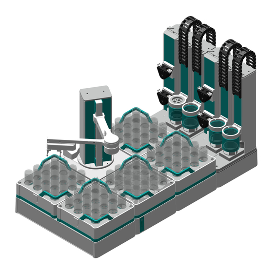
■■■■■■■■■■■■■■■■■■■■■■ Overview – OMNIS Sample Robot Pick&Place L Overview – OMNIS Sample Robot Pick&Place L Figure 3 OMNIS Sample Robot Pick&Place L Main module Pump module Pick&Place module Rack base ■■■■■■■■... -
Page 27: Main Module Pick&Place - Overview
■■■■■■■■■■■■■■■■■■■■■■ Functional description 3.4.1 Main module Pick&Place – Overview Figure 4 Main module Pick&Place – General overview Main lift Arm holder Lift arm Arm joint Gripper arm 3 - 5 Robot arm Gripper Gripper fingers The main lift (4-1) is located on the main module Pick&Place. The arm holder (4-2) connects the lift arm (4-3), the arm joint (4-4) and the gripper arm (4-5) with the main lift. - Page 28 ■■■■■■■■■■■■■■■■■■■■■■ Overview – OMNIS Sample Robot Pick&Place L 3.4.1.1 Main lift – Overview Figure 5 Main lift – Movement capacity Main lift Arm holder Lift arm The lift arm (5-3) can be moved up and down along the main lift (5-1) with the help of the arm holder (5-2).
-
Page 29: Pick&Place Module - Overview
■■■■■■■■■■■■■■■■■■■■■■ Functional description The gripper arm as a whole is moved up and down by the main lift. With the arm joint (6-1), the gripper arm (6-2) can be turned to the left and to the right. The gripper (6-3) can open and close the gripper fingers (6-4), in order to pick up and hold beakers. - Page 30 ■■■■■■■■■■■■■■■■■■■■■■ Overview – OMNIS Sample Robot Pick&Place L At both slide positions (7-5) (front and rear), the titration head holder (7-6) can be moved downwards via the lift tower (7-2) so that the safety shield (7-3) encases the sample beaker. A titration head that fits the sample beaker to be used can be utilized in the titration head holder (7-6).
- Page 31 ■■■■■■■■■■■■■■■■■■■■■■ Functional description Figure 9 Front – Pick&Place module with holder for homogenizer (Poly- tron PT 1300 D) Holder for homogenizer (Polytron PT Polytron PT 1300 D 1300 D) Titration head ■■■■■■■■...
-
Page 32: Peristaltic Pump Module - Overview
■■■■■■■■■■■■■■■■■■■■■■ Overview – OMNIS Sample Robot Pick&Place L 3.4.3 Peristaltic pump module – Overview NOTICE Extension versions 2 or 4 pumps can be mounted per pump module. In the case of the two-way variant, the pumps are mounted on the front only and num- bered 1 and 2. - Page 33 ■■■■■■■■■■■■■■■■■■■■■■ Functional description Rear Figure 11 Rear – Peristaltic pump module Tubing organizer Peristaltic pumps Drain nozzle 2 or 4 peristaltic pumps (11-2) can be fitted on each peristaltic pump module. 2 peristaltic pumps each can be used to rinse and clean the sen- sors in a Pick&Place module.
- Page 34 ■■■■■■■■■■■■■■■■■■■■■■ Overview – OMNIS Sample Robot Pick&Place L Figure 12 Front – Peristaltic pump module with lid tray for OMNIS Sample Robot S Lid tray Figure 13 Front – Peristaltic pump module with lid trays for OMNIS Sample Robot M / L Top lid tray Bottom lid tray ■■■■■■■■...
- Page 35 ■■■■■■■■■■■■■■■■■■■■■■ Functional description 3.4.3.1 Overview – Peristaltic pump Figure 14 Peristaltic pump Press clamp Outlet Inlet Supply and drainage tubing is connected at the inlet (14-3) and outlet (14-2) of the peristaltic pump. A pump tubing is located in the interior of the peristaltic pump between the inlet and the outlet that is pinched off by four rollers.
-
Page 36: Rack Base - Overview
■■■■■■■■■■■■■■■■■■■■■■ Overview – OMNIS Sample Robot Pick&Place L 3.4.4 Rack base – Overview Figure 15 Rack base of an OMNIS sample robot Rack base Rack holder On each rack base (15-1), up to 2 sample racks can be inserted on the rack holders (15-2). -
Page 37: Sample Robot Pick&Place - Functional Description
■■■■■■■■■■■■■■■■■■■■■■ Functional description The sample beakers (16-1) are stored in the sample positions (16-2) in the sample rack. The transport handles (16-3) allow for the sample rack to be transported by hand so that it can be set down on and removed from the rack holder of the rack base. -
Page 38: Main Module Pick&Place - Functional Description
■■■■■■■■■■■■■■■■■■■■■■ Sample Robot Pick&Place – Functional description 3.5.1 Main module Pick&Place – Functional description All of the attached modules in the OMNIS Sample Robot System are sup- plied with electricity through the main module Pick&Place. The main lift with gripper and gripper arm is fastened to the main module Pick&Place. -
Page 39: Rack Base - Functional Description
■■■■■■■■■■■■■■■■■■■■■■ Functional description Optionally, up to 2 lid trays can be installed on the pump module. The lid that was removed from the sample beaker is parked on the lid tray until it is needed again to seal the sample beaker. If malfunctions occur at the peristaltic pump, this will be displayed via LED at the peristaltic pump. -
Page 40: Omnis Sample Robot - Indicators And Controls
■■■■■■■■■■■■■■■■■■■■■■ OMNIS Sample Robot – Indicators and controls OMNIS Sample Robot – Indicators and controls Figure 17 OMNIS Sample Robot – Indicators and controls On/off switch Status display Multi-colored Indicators The status of the instrument is displayed with the status display (17-2) using different colors System –... -
Page 41: Main Module - Connectors
■■■■■■■■■■■■■■■■■■■■■■ Functional description Main module – Connectors NOTICE Symbol labeling Observe the connector symbols when connecting the instruments. Figure 18 Connectors – Main module Pick&Place Human Interactive Device (HID) Local Area Network (LAN) Metrohm Device Link (MDL) Power socket ■■■■■■■■... -
Page 42: Transport And Storage
If it is necessary to lift the sample robot, try to avoid a sag by lifting the system on all four sides. Take the total weight of the system into account. Check the positioning accuracy of the sample robot after placing the sam- ple robot down. If inaccuracies occur, Metrohm support will assist you. ■■■■■■■■... -
Page 43: Installation
As a basic rule, the installation of the system and of the new products and modules is handled by trained and instructed specialists from the Metrohm Company and/or its representative. Sample robot setting up The product has been developed for operation indoors and may not be used in explosive environments. -
Page 44: Replacing The Seal Of The Sample Beaker Lid
250 mL standard seals 6.02710.050 Lid for sample beaker 250 mL (P&P) with 250 mL resistant seals NOTICE The accessories for the respective product version can be obtained either on the Internet at http://www.metrohm.com or via your regional Metrohm representative. ■■■■■■■■... - Page 45 ■■■■■■■■■■■■■■■■■■■■■■ Installation Figure 19 Sample beaker lid with seal for sample beaker lid (complete) Placing the seal onto the sample beaker lid 1 Placing and fitting the lid seal Figure 20 Placing the rubber seal onto the lid Slide the rubber seal from below over the lid bottom so that it sits neatly in the prefabricated groove.
-
Page 46: Inserting And Equipping The Titration Head
■■■■■■■■■■■■■■■■■■■■■■ Inserting and equipping the titration head Removing the seal of the sample beaker lid 1 Pull the lid seal down over the lid bottom and remove it. Inserting and equipping the titration head NOTICE The titration head has the markings "LOCK" for closed and "UNLOCK" for open, also see Replacing the titration head (see chapter 8.4.3, page 73). - Page 47 ■■■■■■■■■■■■■■■■■■■■■■ Installation The safety shield is dismounted. ■ 1 Inserting the titration head Insert the titration head (21-1) from below into the titration head holder (21-2). NOTICE In case a rod stirrer is used: The marked opening (triangle or arrow) for inserting the rod stir- rer on the titration head should be located as close as possible to the tower of the Pick&Place module.
- Page 48 ■■■■■■■■■■■■■■■■■■■■■■ Inserting and equipping the titration head Equipping the titration head for titration Figure 23 Positions of the components in the titration head (titration with rod stirrer) Position for the spray nozzles or rins- Position for the electrode ing nozzles Position for the aspiration tip Position for the preinstalled dosing tips for connecting dosing tubing...
- Page 49 ■■■■■■■■■■■■■■■■■■■■■■ Installation 2 Inserting the electrode Insert the electrode from above into the position intended for this purpose. 3 Mounting the aspiration tubing Insert the aspiration tip from above into the position intended for this purpose and mount the aspiration tubing. If necessary, shorten the aspiration tip to the desired length after- wards.
- Page 50 ■■■■■■■■■■■■■■■■■■■■■■ Inserting and equipping the titration head Equipping the titration head for Karl Fischer titration Figure 24 Positions of the components in the KF titration head Buret tip for titrant Dosing tip for reagent (Solvent) Preinstalled dosing tip with antidiffusion Preinstalled dosing tip with antidiffusion valve valve...
- Page 51 ■■■■■■■■■■■■■■■■■■■■■■ Installation NOTICE Depending on the application, the stopper can also be replaced by an aspiration tip to aspirate the solution after the titration. The aspiration tip might need to be shortened to the desired length and an aspiration tubing must be mounted. 2 Inserting the buret tip for the titrant Insert the buret tip into the screw nipple on the left, mount the titra- tion tubing and screw it tight.
-
Page 52: Mounting The Safety Shield
■■■■■■■■■■■■■■■■■■■■■■ Mounting the safety shield Mounting the safety shield WARNING Working without a safety shield A risk of injury exists when working without a safety shield mounted. Never operate the sample robot without a safety shield. ■ Before beginning work, make sure that all of the protective devi- ■... - Page 53 ■■■■■■■■■■■■■■■■■■■■■■ Installation Mounting the safety shield Prerequisites: The sample robot is switched off ■ 1 Inserting the safety shield Insert the safety shield (25-1) from the bottom into the titration head holder (25-2). 2 Fastening the safety shield Figure 26 Fastening the safety shield Rotate the safety shield clockwise until the marking points to "LOCK".
-
Page 54: Connecting The Tubing To The Distributor Of The Pick&Place Module
■■■■■■■■■■■■■■■■■■■■■■ Connecting the tubing to the distributor of the Pick&Place module Connecting the tubing to the distributor of the Pick&Place module Figure 27 Connecting the tubing to the distributor Rinsing tubing Aspiration tubing Distributor Rinsing tubing Outlet tubing Connecting the tubing to the distributor Prerequisites: The sample robot is switched off ■... - Page 55 ■■■■■■■■■■■■■■■■■■■■■■ Installation 2 Connecting the aspiration tubing Manually tighten the aspiration tubing (27-2) in the M3 bore hole of the distributor. 3 Connecting the rinsing tubing Remove the union nut. Pull the end of the tubing over the connection nipple of the distribu- tor and fasten in place with the union nut.
-
Page 56: Connecting The Drainage Tubing
■■■■■■■■■■■■■■■■■■■■■■ Connecting the drainage tubing Connecting the drainage tubing Connecting and placing the drainage tubing Push the tubing adapter (1) in an angle of 30 degrees (see illustra- tion) onto the drain nozzle. ■■■■■■■■... -
Page 57: Connecting The Inlet And Outlet Tubing
■■■■■■■■■■■■■■■■■■■■■■ Installation Plug the drainage tubing (2) in the tubing adapter and guide it through the tubing duct (3) to the waste canister (red line). Take care that the tubings are not bent upwards to prevent liquids from back- ing up. Connecting the inlet and outlet tubing Figure 28 Connecting the inlet and outlet tubing... -
Page 58: Connecting/Disconnecting The Power Cord
■ sockets) against moisture. If you suspect that moisture has gotten into the product, discon- ■ nect the product from the energy supply. Then notify Metrohm Service. Only personnel who have been issued Metrohm qualification may ■ perform service and repair work on electrical and electronic com- ponents. - Page 59 ■■■■■■■■■■■■■■■■■■■■■■ Installation Power cord with a maximum length of 2 m, three-core with IEC 60320 instrument plug type C13. Conductor cross-section 3x 0.75 mm / 18 AWG. Power plug according to customer requirements (6.2122.XX0), designed for a minimum of 10 A. 1 Plugging in the power cord Plug the power cord into the product's power socket.
-
Page 60: Initial Start-Up
Initial start-up by Metrohm NOTICE Initial start-up of the product As a basic rule, the initial start-up of the system and of the new prod- ucts and modules is handled by trained and instructed specialists from the Metrohm Company and/or its representative. ■■■■■■■■... -
Page 61: Operation And Control
■■■■■■■■■■■■■■■■■■■■■■ Operation and control 7 Operation and control Operation NOTICE Operating via the control software The product can be operated using the commands of the control software. Additional information can be found in the software help . Switching the OMNIS sample robot on and off Switching the OMNIS sample robot on and off The on/off switch is located on the main module of the sample... -
Page 62: Opening The Gripper Manually
■■■■■■■■■■■■■■■■■■■■■■ Opening the gripper manually NOTICE Additional information on the controls, see OMNIS Sample Robot – Indicators and controls (see chapter 3.6, page 32). Opening the gripper manually CAUTION Unsecured sample beakers If the gripper is opened, then unsecured sample beakers can cause injuries and property damage to the instrument. -
Page 63: Attaching And Removing The Sample Rack
The use of non-authorized sample beakers in the OMNIS Sample Robot System can lead to injuries and considerable property damage. Use only sample beakers that are authorized by Metrohm. ■ NOTICE Because of the shape of the rack holder and the counterpart on the sample rack, only one position exists at which the sample rack can be properly placed on the rack base. - Page 64 ■■■■■■■■■■■■■■■■■■■■■■ Attaching and removing the sample rack Figure 30 Overview image – Attaching and removing the sample rack Rack base Rack holder Sample rack Transport handles Attaching a sample rack 1 Attaching a sample rack Figure 31 Attaching a sample rack Grip the sample rack (30-3) on the transport handles (30-4) with both hands and set it down on the rack base (30-1).
- Page 65 ■■■■■■■■■■■■■■■■■■■■■■ Operation and control 2 Pushing in the sample rack Figure 32 Pushing in the sample rack Push the sample rack towards the front until it is firmly seated on the rack holder (30-2). NOTICE A brief acoustic signal will sound as soon as the sample rack is seated correctly on the rack base and the rack holder.
-
Page 66: Maintenance
Only perform maintenance work that is described in this instruction. Con- tact the Metrohm service for further maintenance and repairing works. Disconnect the product from the power grid prior to any maintenance and cleaning. -
Page 67: Maintenance Agreement
■ sockets) against moisture. If you suspect that moisture has gotten into the product, discon- ■ nect the product from the energy supply. Then notify Metrohm Service. Only personnel who have been issued Metrohm qualification may ■ perform service and repair work on electrical and electronic com- ponents. -
Page 68: Cleaning The Product
■ sockets) against moisture. If you suspect that moisture has gotten into the product, discon- ■ nect the product from the energy supply. Then notify Metrohm Service. Only personnel who have been issued Metrohm qualification may ■ perform service and repair work on electrical and electronic com- ponents. -
Page 69: Cleaning The Pick&Place Module
Maintenance NOTICE If the suspicion arises that liquids have found their way into the product, disconnect the product from the power grid and con- tact your Metrohm Service. NOTICE Water or ethanol can be used as a cleaning medium. NOTICE The connectors at the rear of the product must only be cleaned with a dry cloth. - Page 70 ■■■■■■■■■■■■■■■■■■■■■■ Cleaning the product NOTICE The safety shield has the designations "LOCK" for closed and "UNLOCK" for open. Figure 33 Cleaning the safety shield Safety shield Titration head holder Markings "LOCK" and "UNLOCK" Cleaning the safety shield Prerequisites ■■■■■■■■...
- Page 71 ■■■■■■■■■■■■■■■■■■■■■■ Maintenance The instrument is disconnected from the power grid. ■ 1 Dismantling the safety shield Figure 34 Dismantling the safety shield Grip the safety shield (33-1) with one hand and rotate it counter- ■ clockwise until the marking points to "UNLOCK" (33-3). Remove the safety shield downwards out of the titration head ■...
- Page 72 ■■■■■■■■■■■■■■■■■■■■■■ Cleaning the product 3 Inserting the safety shield Figure 35 Inserting the safety shield Insert the safety shield from the bottom into the titration head holder. 4 Fastening the safety shield Figure 36 Fastening the safety shield Rotate the safety shield clockwise until the marking points to "LOCK".
- Page 73 ■■■■■■■■■■■■■■■■■■■■■■ Maintenance Figure 37 Cleaning the slide and collection tray Slide Collection tray Cleaning the slide and collection tray Prerequisites The instrument is disconnected from the power grid. ■ 1 Removing the slide Figure 38 Removing the slide Remove the slide (37-1) by hand upwards out of the collection tray (37-2).
- Page 74 ■■■■■■■■■■■■■■■■■■■■■■ Cleaning the product NOTICE The slide is fastened to the guide rails of the Pick&Place module with four magnets. 2 Cleaning the slide NOTICE Clean carefully as the electronic board is open. Remove dust and dirt from the slide with a damp cloth. 3 Cleaning the base plate Remove dust and dirt from the base plate with a damp cloth.
-
Page 75: Checking And Replacing Product Parts
■ sockets) against moisture. If you suspect that moisture has gotten into the product, discon- ■ nect the product from the energy supply. Then notify Metrohm Service. Only personnel who have been issued Metrohm qualification may ■ perform service and repair work on electrical and electronic com- ponents. -
Page 76: Replacing The Finger Tip And Ptfe Sleeve
■■■■■■■■■■■■■■■■■■■■■■ Checking and replacing product parts 8.4.1 Replacing the finger tip and PTFE sleeve Figure 40 Replacing the finger tip and PTFE sleeve Gripper Gripper finger PTFE sleeve Finger tip Retainer Dismantling the finger tip and PTFE sleeve Prerequisites The sample robot is switched off. ■... - Page 77 ■■■■■■■■■■■■■■■■■■■■■■ Maintenance NOTICE A slot to facilitate assembly and disassembly is located in the PTFE sleeve. The PTFE sleeve can be stretched over this slot, e.g., with a small screwdriver or fingernail, and then subsequently removed via the lower section on the gripper finger. Mounting the finger tip and PTFE sleeve Prerequisites The sample robot is switched off.
-
Page 78: Replacing The Beaker Adapter
■■■■■■■■■■■■■■■■■■■■■■ Checking and replacing product parts 8.4.2 Replacing the beaker adapter Figure 41 Replacing the beaker adapter Slide Ring Beaker adapter Table 9 Available beaker adapters and settings Beaker vol- Beaker diam- Beaker height Article num- eter 75 mL 35.5 mm 113 mm 6.01404.040 120 mL... - Page 79 ■■■■■■■■■■■■■■■■■■■■■■ Maintenance The slide is extended ■ 1 Removing the ring Figure 42 Removing the ring Rotate the ring (41-2) counterclockwise by hand and remove towards the top from the slide (41-1). 2 Removing the beaker adapter Figure 43 Removing the beaker adapter Remove the beaker adapter (41-3) out of the slide by hand from above.
- Page 80 ■■■■■■■■■■■■■■■■■■■■■■ Checking and replacing product parts 3 Inserting the beaker adapter Figure 44 Inserting the beaker adapter Make sure that the correct values for the beaker diameter and beaker height (see "Available beaker adapters and settings" table) are entered for the respective Pick&Place module in the OMNIS Software. The value can be modified in the Instruments area under Proper- ties / Specific data.
-
Page 81: Replacing The Titration Head
■■■■■■■■■■■■■■■■■■■■■■ Maintenance 4 Fastening the ring Figure 45 Fastening the ring Attach the ring by hand to the slide and tighten clockwise. 8.4.3 Replacing the titration head Figure 46 Replacing the titration head Titration head Titration head holder Markings "LOCK" and "UNLOCK" Table 10 Available titration heads ■■■■■■■■... - Page 82 ■■■■■■■■■■■■■■■■■■■■■■ Checking and replacing product parts Beaker Stirring pro- Openings / des- Article volume peller ignations number 75 mL 4xM10 6.01403.010 6.01900.020 75 mL 4xM10 for KFT 6.01403.020 75 mL 2xSGJ14, 1xM10 6.01403.040 120 mL 6.01900.030 3xSGJ14, 4x6.4mm 6.01403.030 200 mL 6.01900.030 3xSGJ14, 4x6.4mm 6.01403.060...
- Page 83 ■■■■■■■■■■■■■■■■■■■■■■ Maintenance 2 Inserting the titration head Figure 48 Inserting the titration head Insert the titration head from the bottom into the titration head holder. 3 Fastening the titration head Figure 49 Fastening the titration head Rotate the titration head by hand until the marking points to "LOCK". ■■■■■■■■...
-
Page 84: Checking The Pump Tubing
■■■■■■■■■■■■■■■■■■■■■■ Checking and replacing product parts 8.4.4 Checking the pump tubing NOTICE Interval The pump tubing must be checked each time before starting work. Figure 50 Removing the press clamp Press clamp Removing the press clamp Prerequisites: The sample robot is disconnected from the power grid. ■... - Page 85 ■■■■■■■■■■■■■■■■■■■■■■ Maintenance NOTICE Daily/continuous checking The pump tubing is comprised of wear parts and is susceptible to leaks and damage. Check the pump tubing daily and/or continuously. ■ Replace worn and/or damaged pump tubing. ■ ■ 1 Perform a visual inspection of the pump tubing. Note any cracking or leaking liquid while doing so.
-
Page 86: Replacing The Pump Tubing
Use the following pump tubing: Light-colored tubing from Pharm-A-line™ (6.01801.020) with ■ white press clamp (6.02703.000). Only pump tubing that has been authorized by Metrohm may be used. Dismantling the pump tubing Prerequisites: The sample robot is disconnected from the power grid. - Page 87 ■■■■■■■■■■■■■■■■■■■■■■ Maintenance 2 Removing the press clamp Figure 53 Removing the press clamp Pull one side of the press clamp (1) outwards by hand. ■ Pull off the other side. ■ Remove the press clamp. ■ 3 Removing the pump tubing Figure 54 Removing the pump tubing Pull one of the connecting elements of the pump tubing outwards by...
- Page 88 ■■■■■■■■■■■■■■■■■■■■■■ Checking and replacing product parts NOTICE The pump tubing is positioned close to the inner rollers for opti- mum conveyance of the media. It is for that reason that a cer- tain amount of force must be applied for disassembling the first connecting element.
- Page 89 ■■■■■■■■■■■■■■■■■■■■■■ Maintenance Figure 56 Placing the pump tubing around rollers Place the pump tubing around the rollers and slide the second con- necting element up on the other side until it stops in the guide rail as well. NOTICE The position of the pump tubing must be close and snug to the rollers for optimum conveyance of the media.
- Page 90 ■■■■■■■■■■■■■■■■■■■■■■ Checking and replacing product parts 2 Mounting the press clamp Figure 57 Mounting the press clamp NOTICE Do not fasten or loosen the hex screws of the press clamps. Insert one side of the press clamp with the lug into the groove ■...
-
Page 91: Malfunctions And Troubleshooting
Malfunctions have to be solved directly on the product. If applicable, ■ this can be done with the help of the control software (e.g. initializa- tion, move to defined position, etc.). NOTICE Additional information can be found in the context-sensitive software help or on https://guide.metrohm.com. ■■■■■■■■... -
Page 92: Disposal
■■■■■■■■■■■■■■■■■■■■■■ 10 Disposal This product is covered by European Directive, WEEE – Waste Electrical and Electronic Equipment. The correct disposal of your old product will help to prevent negative effects on the environment and public health. More details about the disposal of your old product can be obtained from your local authorities, from waste disposal companies or from your local dealer. -
Page 93: Technical Specifications
■■■■■■■■■■■■■■■■■■■■■■ Technical specifications 11 Technical specifications 11.1 Ambient conditions Nominal function range +5 °C - +45 °C at a maximum of 85% humidity Storage and transport –20 °C - +70 °C 11.2 Main module – Energy supply Nominal voltage range 100 VAC - 240 VAC Nominal frequency range 50 Hz - 60 Hz... -
Page 94: Peristaltic Pump Module - Energy Supply
■■■■■■■■■■■■■■■■■■■■■■ Peristaltic pump module – Energy supply 11.4 Peristaltic pump module – Energy supply Nominal voltage 24 VDC internal Power consumption Peristaltic pump max. 10 W per pump Protection Internal fuse 1.5 ATH cannot be replaced by the user 11.5 OMNIS sample rack –... -
Page 95: Main Module Pick&Place - Dimensions
■■■■■■■■■■■■■■■■■■■■■■ Technical specifications 11.7 Main module Pick&Place – Dimensions Measurements Width Main module S 558 mm Main module M 1,161 mm Main module L 1,441 mm Height Main module S, M, L Without workstation 585 mm Main module S, M, L With workstation 758 mm Depth... -
Page 96: Pick&Place Module - Dimensions
■■■■■■■■■■■■■■■■■■■■■■ Pick&Place module – Dimensions 11.8 Pick&Place module – Dimensions Measurements Width 92 mm Height 746 mm Depth 289 mm Weight Without magnetic stirrer 4.0 kg With magnetic stirrer 4.4 kg 11.9 Peristaltic pump module – Dimensions Measurements Width 92 mm Height 585 mm Depth... -
Page 97: Omnis Rack Base / Omnis Module Base - Dimensions
■■■■■■■■■■■■■■■■■■■■■■ Technical specifications 11.10 OMNIS rack base / OMNIS module base – Dimen- sions Measurements Width 280 mm Height 115 mm Depth 564 mm Weight OMNIS rack base 3.9 kg Module base M/L 4.6 kg 11.11 OMNIS sample rack – Dimensions Measurements Width 277 mm... -
Page 98: Main Module Pick&Place - Housing
■■■■■■■■■■■■■■■■■■■■■■ Main module Pick&Place – Housing 11.12 Main module Pick&Place – Housing Materials poly(butylene tereph- thalate) Back panel AW-5754 H12 / H22 aluminum, coated AlSi12Cu1 aluminum, coated Base Enclosure poly(butylene tereph- thalate) polypropylene Front foils poly(ethylene tereph- thalate), mat IP degree of protection IP 20 11.13 Pick&Place module –... -
Page 99: Peristaltic Pump Module - Housing
■■■■■■■■■■■■■■■■■■■■■■ Technical specifications 11.14 Peristaltic pump module – Housing Materials poly(butylene tereph- thalate) Back panel AW-5754 H12 / H22 aluminum, coated poly(butylene tereph- Base thalate) Enclosure polypropylene Lid tray AW-5754 H12 / H22 aluminum, coated IP degree of protection IP 20 11.15 OMNIS Sample Robot Pick&Place –... -
Page 100: Omnis Sample Rack - Housing
Conductor cross-section min. 0.75 mm / 18 AWG Plug Instrument side IEC 60320, type C13, 10 A Building side country-specific Metrohm Device Link 4 connectors Human Interactive Device Local Area Network Type Ethernet CAT 6 Socket RJ45 shielded Cable type (min. -
Page 101: Omnis Sample Robot Module - Connectors Specifica- Tions
Contact surfaces for OMNIS sample rack 11.19 OMNIS Sample Robot module – Connectors specifi- cations Energy supply internally via MDL Metrohm Device Link 4 internal connectors 11.20 OMNIS rack base – Connectors specifications Contacts Contact surfaces for OMNIS sample rack 11.21 OMNIS sample rack –... -
Page 102: Magnetic Stirrer - Stirrer Specifications
3.7 N typical Speed 15 mm/s - 75 mm/s Gripper type with beaker diameter Range 25.6 mm - 71.6 mm from Metrohm accesso- ries Rack positions Sample Robot S 1 - 2 Sample Robot M 1 - 5 Sample Robot L 1 - 7 ■■■■■■■■... -
Page 103: Omnis Sample Rack - Sample Handling Specifications
■■■■■■■■■■■■■■■■■■■■■■ Technical specifications 11.26 OMNIS sample rack – Sample handling specifica- tions Rack types Number of sample positions 9, 16, 25 from Metrohm accesso- ries ■■■■■■■■...
Need help?
Do you have a question about the OMNIS Sample Robot Pick&Place and is the answer not in the manual?
Questions and answers