Table of Contents
Advertisement
Advertisement
Table of Contents

Subscribe to Our Youtube Channel
Related Manuals for Dentsply Sirona X-Smart Plus


Summary of Contents for Dentsply Sirona X-Smart Plus
- Page 1 User Manual...
- Page 2 PAGE INTENTIONALLY LEFT BLANK 2/60 BENXSPSDFUWEB / Rev.09 / 10-2018...
-
Page 3: Table Of Contents
Table of Contents Table of Contents Indications for use ........6 Contraindications . - Page 4 Table of Contents Factory Default Parameters ....... 34 Battery Refresh ......... 35 6.10 Displaying the Software Version .
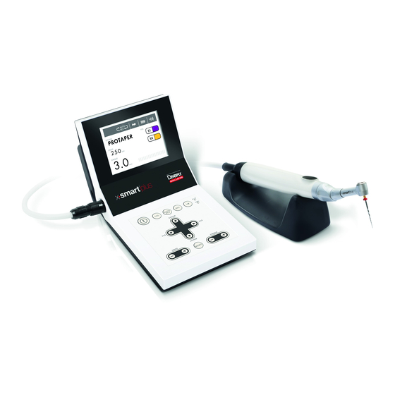
- Page 5 FOR DENTAL USE ONLY Introduction ® Congratulations on your purchase of the X-Smart Plus endo motor. Read this User Manual carefully before use for operating instructions, care and maintenance. Keep this manual for future reference. BENXSPSDFUWEB / Rev.09 / 10-2018 5/60...
-
Page 6: Indications For Use
Indications for use INDICATIONS FOR USE ® The X-Smart Plus endo motor is a medical device according to the Medical Device Directive 93/42/EEC, designed for use by dentists for driving dental root canal instruments in continuous rotation and in reciprocating movement. This device must only be used in hospital environments, clinics or dental offices by qualified dental personnel. - Page 7 Use the specified battery for this device. Never use any other batteries than those that Dentsply Sirona specifies. • Use the Dentsply Sirona AC adapter for this device. Never use any other AC adapters. • If you should notice battery fluid leak, deformation of the motor handpiece casing or partial discoloring, immediately stop use and contact your distributor.
- Page 8 Warnings • In order to avoid possible risks due to electromagnetic interference, do not use any electrical medical device or electrical device of any ® other kind in close proximity to the X-Smart Plus. The electromagnetic radiation emitted by the device is below the recommended limits set forth in pertinent regulations in force...
- Page 9 Warnings • The plastic enclosure is not sealed, do not use any liquid or spray directly on the unit, especially on the monitor or near the electrical sockets. • Do not crimp the cords exiting the motor handpiece and AC adapter.
-
Page 10: Precautions
Precautions • Do not lubricate the motor handpiece for any reason, as lubricant contamination of the motor handpiece might damage it and may have a strong negative effect on its safe operation. • Never introduce any foreign objects into the motor handpiece shaft. •... - Page 11 Precautions • Before changing the contra-angle or file, turn off the power of the unit. Changing with the power kept on may cause unintended rotation by accidental touch of the ON/OFF key. • Always clean the shank of the file to be installed. Allowing dirt to enter the chuck could cause loss of concentricity and deterioration of chucking force.
-
Page 12: Adverse Reactions
Adverse Reactions • Modifications or repairs performed by persons not authorized by the manufacturer. • Use of non-original components or components other than those specified in the STANDARD COMPONENTS chapter (see chapter 6.1). • File breakage due to misuse. •... -
Page 13: Standard Components
Step-by-Step Instructions Standard Components ® The X-Smart Plus is supplied with the components listed below: Control unit Motor handpiece with cable and connector ® Plus 6:1 contra-angle X-Smart Handpiece stand F-type spray nozzle (used for lubrication) AC adapter, model Cincon Electronics Co. Ltd, TR30RAM180 with EU, UK, USA, AUS exchangeable plugs Torque card User Manual... -
Page 14: Operation Panel
Step-by-Step Instructions Operation Panel Fig. 1 Operation Panel Switches the device on and off (keep POWER pressed for more than 2 seconds). Adjust the rotation speed (possible only SPEED + / - for continuous rotary systems). Adjust the torque limit (possible only for TORQUE + / - continuous rotary systems). - Page 15 Step-by-Step Instructions Changes the rotational direction of the file (only possible for continuous rotary systems).The rotational direction can also be changed while the file is in motion. Only for continuous rotary systems, selects one of the 3 auto reverse modes (see chapter 6.5.4 Inserting and Removing the File):...
-
Page 16: Lcd Panel
Step-by-Step Instructions LCD Panel Fig. 2 LCD Panel Displays the selected file system (See SYSTEM chapter 6.6.1 File Library). Displays the selected file(s) (See FILE chapter 6.6.1 File Library). Displays the instrument rotation speed value (disabled for reciprocating SPEED systems). Displays the torque limit value TORQUE (disabled for reciprocating systems). - Page 17 Step-by-Step Instructions Displays the selected auto reverse mode (disabled for reciprocating systems) 3 modes can be selected (see AUTO REVERSE chapter 6.6.4 Auto Reverse Function). AUTO REVERSING: AUTO STOP: AUTO REVERSE OFF: (No mark) Displays the current rotational direction ROTATIONAL of the file.
- Page 18 Step-by-Step Instructions Displays the present remaining amount of the battery. The mark is animated BATTERY when the battery is charging (see chapter 6.5.5 Charging the Battery) Full charge Approximately 30-80% remains Less than 30% remains. In this case, the auto reverse function may not activate (See chapter 6.6.4 Auto...
-
Page 19: Preparation
Step-by-Step Instructions Preparation Carefully remove the device and the accessories from their packaging and place them on a flat surface. Check that all the components listed in the STANDARD COMPONENTS chapter (see chapter 6.1) are present. Remove the protective plastic film from the operation panel. WARNING Should any liquid exit the device, interrupt the installation immediately and send the machine to your distributor. - Page 20 Step-by-Step Instructions Place the required plug adapter onto the two contacts on the power supply and push it toward the locking button (B) until it snaps into place. You must press the locking button (B) to change the adapter (see Fig.
-
Page 21: Connecting And Disconnecting The Motor Handpiece
Step-by-Step Instructions 6.5.2 Connecting and Disconnecting the Motor Handpiece Connecting Align the mark of the cord plug with the ▲ mark of the unit connector (B - see Fig. 4) at the left side of the device and insert the plug until it locks. -
Page 22: Inserting And Removing The File
Step-by-Step Instructions 6.5.4 Inserting and Removing the File File insertion Insert the file into the chuck until it stops. Lightly turn the file until it engages with the latch mechanism. Push inwards to click. File removal Press the push-button and pull out the file (see Fig. - Page 23 Step-by-Step Instructions NOTE • There is no need to turn the power on to charge the battery. • The AC-IN lamp lights to indicate that the supply power is on. It does not go out even after a charge is completed. See the CHRG lamp to check the charging conditions.
-
Page 24: Calibration
Step-by-Step Instructions 6.5.6 Calibration This function is to decrease fluctuation in the rotation speed of the motor handpiece and the difference in torque by the contra-angle. Calibration is recommended when using a new/other contra-angle or after an extended period of operation, as the running properties can change with usage, cleaning and sterilization. -
Page 25: Sound Volume Adjustment
Step-by-Step Instructions • Then, the display returns to its original state. NOTE • Should you at any time wish to stop the calibration process, turn the power off. • Calibrate every time the contra-angle is lubricated or replaced after sterilizing, or at least once a week (see chapters 6.11.2 Lubricating the Contra-angle 6.12 Cleaning, Disinfection... -
Page 26: Operation
Step-by-Step Instructions Operation 6.6.1 File Library The device contains a file library with the following preset NiTi systems: A. Continuous rotary systems • Gates ® • Proglider ® • PathFile ® • Protaper Next ® • ProtaperGold ® • Protaper Universal •... -
Page 27: Switch-On And Switch-Off The Unit
Step-by-Step Instructions 6.6.2 Switch-on and Switch-off the Unit Switch-on Hold down the POWER key for more than 2 seconds. A welcome screen is displayed. Then, the display will read the first file in the system last used before switching the device off. Switch-off Hold down the POWER key for more than 2 seconds. -
Page 28: Switch-On And Switch-Off The Motor Handpiece
Step-by-Step Instructions 6.6.3 Switch-on and Switch-off the Motor handpiece • If you press the ON/OFF key briefly, the motor handpiece starts. If you re-press the key, it stops. • If you hold down the ON/OFF button for more than 1 second, the motor handpiece starts while the key is pressed. -
Page 29: Auto Reverse Function
Step-by-Step Instructions 6.6.4 Auto Reverse Function There are 3 different auto reverse modes: AUTO REVERSING: If, during operation the load reaches the preset torque limit value, the motor handpiece will automatically rotate in the reverse direction. When the load is removed, the motor handpiece returns to normal forward rotation automatically. -
Page 30: Selecting A File System
Step-by-Step Instructions AUTO REVERSE OFF: If, during operation the load reaches the preset torque limit value, the motor handpiece will stop without reverse rotation. The LCD panel shows " " and the rotation speed alternately. If you want the file to rotate forward again, press the ON/OFF key twice. When the motor handpiece starts and its load reaches approximately half of the preset torque limit value, the alarm sounds (corresponding to on the bar display). -
Page 31: Continuous Rotary File Systems
Step-by-Step Instructions 6.7.1 Continuous Rotary File Systems When a file system has been selected, the first file of the system will automatically be shown in the display. Press the FILE ► key to select the next file. Press the FILE ◄ key to select the previous file. WARNING Do not use files designed for reciprocating motion in continuous rotation. - Page 32 Step-by-Step Instructions The reciprocating files of the system are shown on the right part of the display. WARNING Do not use files designed for continuous rotation in reciprocating motion. NOTE • For reciprocating files, the settings including speed and torque cannot be adjusted.
-
Page 33: Program" For Continuous Rotary File Systems
Step-by-Step Instructions 6.7.3 "Program" for Continuous Rotary File Systems For convenience, the device is delivered with 2 programs with default values of torque and speed (see chapter 13 Program - Individual Continuous Rotary Program). Press the FILE ► key to select the next program number. Press the FILE ◄... -
Page 34: Factory Default Parameters
Step-by-Step Instructions When the desired continuous rotary file is selected, press the + or - SPEED keys to select the desired speed setting. When the speed value is changed from the default setting, SPEED is displayed between brackets. If the MEMO key is not pressed to save the setting, the setting will be lost once a different file setting is selected. -
Page 35: Battery Refresh
Step-by-Step Instructions • During the process the display will read: • When the process is completed, the display reads: • Then, the display returns to the first system of the file library. NOTE • This function is not activated unless the device is powered by the AC adapter. -
Page 36: Displaying The Software Version
Step-by-Step Instructions Turn the power off. Connect the AC adapter and check that the AC-IN lamp lights (see chapter 6.5.1 Connecting the AC adapter). Hold down the POWER key for more than 2 seconds, while pressing the REV key. A sound appears for a length of time, and the refresh mode is activated. At this time, the CHRG lamp flashes slowly. -
Page 37: Maintenance
When replacing, be sure to observe the following "PRECAUTIONS ON CHANGING BATTERY". Note that Dentsply Sirona shall not be held liable for any malfunction or failure resulting from the failure to follow the "PRECAUTIONS ON CHANGING BATTERY". - Page 38 Step-by-Step Instructions The battery compartment is located at the rear of the unit and its cover is secured by a screw located on the bottom of the unit. Turn the power off. Disconnect the AC adapter. Remove the screw fixing the cover with a screw driver. Slide the cover down slightly in the direction of the arrow (toward the bottom) and remove it.
-
Page 39: Lubricating The Contra-Angle
Step-by-Step Instructions 6.11.2 Lubricating the Contra-angle • Lubricate the contra-angle only with a dedicated spray. • Lubricate after each use and before sterilization. Screw the spray nozzle onto the spray with approx. 10 turns. F type Spray Nozzle Contra-angle Insert the spray nozzle into the rear part of the contra-angle and lubricate for 2-3 seconds until oil comes out from the contra-angle head. -
Page 40: Cleaning, Disinfection And Sterilization
Step-by-Step Instructions 6.12 Cleaning, Disinfection and Sterilization 6.12.1 Foreword For hygiene and sanitary safety purposes, the contra-angle must be cleaned, disinfected and sterilized before each usage to prevent any contamination. This concerns the first use, as well as all subsequent uses. -
Page 41: Step-By-Step Procedure
Step-by-Step Instructions 6.12.3 Step-by-Step Procedure For contra-angle only Operation Operating Mode Warning Remove the contra- angle from the motor Preparation handpiece and detach the files from the chuck. • Avoid any contact between the contra- angle and any instruments, kits, supports or container. - Page 42 Step-by-Step Instructions • Use only autoclaves that are matching the requirements of EN 13060, EN 285. • Use a validated sterilization procedure according to ISO 17665. • Respect the maintenance procedure of the autoclave device given by the manufacturer. Steam sterilization at Sterilization 134°C (274°F) for...
-
Page 43: Technical Specifications
Technical Specifications TECHNICAL SPECIFICATIONS The device complies with IEC60601-1 safety and IEC60601-1-2 EMC (Electromagnetic compatibility) standards and the requirement of CE Marking of Conformity. 0086 Classifications of equipment • Essential Performance: No Essential Performance as of IEC 60601-1 meaning. •... -
Page 44: Product Main Specifications
Technical Specifications Product Main Specifications ® X-Smart Plus control unit Model NE274/NE298 Torque range 0.6 - 4.0 Ncm in continuous rotation Speed range 250 - 1200 rpm in continuous rotation Rated input DC 18 V 0.5 A Charging time 5 hours approx. Dimensions W107 x D196 x H107 mm Weight... - Page 45 Technical Specifications ® X-Smart Plus AC adapter TR30RAM180 Model CINCON ELECTRONICS CO.,LTD Input AC 100-240 V 47-63 Hz Output DC 18 V 1.67 A Dimensions W62 x D37 x H109 mm Weight 300 g ENVIRONMENTAL CONDITIONS FOR USE Temperature 10°C - 40°C (50°F - 104°F) Humidity 30% - 75% Atmospheric pressure...
-
Page 46: Error Code
Error Code ERROR CODE If the motor handpiece stops due to an abnormality such as a malfunction, overload or breakage due to misuse, it automatically checks the state of the control unit. It detects the cause of the abnormality and displays an error code on the LCD panel. If an error code is displayed, turn on the power again and check whether the same error code is displayed. - Page 47 Error Code Error Error Cause Check/Remedy code Contact your E-00 Self-Check Malfunction of circuit. distributor. The motor handpiece is locked (at the time Remove load. of the auto reverse E-01 Over current mode). The motor handpiece Contact your During cord has shorted. distributor.
- Page 48 Error Code Error Error Cause Check/Remedy code High load was continuously applied Let the motor cool Overheating of to the motor E-04 down before motor handpiece for a resuming operation. relatively long period of time. Abnormal voltage generated in start / stop circuit.
- Page 49 Error Code Error Error Cause Check/Remedy code The battery current is Put the battery into too low or too high. the battery E-10 Battery current The battery is flat or compartment or not inserted. replace the battery. Contact your E-11 Display Faulty display driver.
-
Page 50: Troubleshooting
Troubleshooting TROUBLESHOOTING When trouble is found, check the following points before contacting your distributor. If none of these are applicable or the trouble is not remedied even after action has been taken, the product may have failed. Contact your distributor. ®... - Page 51 Troubleshooting Problem Cause Solution If the temperature of the battery is less than 0°C (32°F), the battery is not The temperature of the rechargeable. Charge the battery is low. battery in a warm room. Be careful about moisture condensation. The AC adapter does It is normal that the battery not work.The CHRG temperature is slightly...
-
Page 52: Warranty
Warranty Problem Cause Solution When turning on the The power is turned on while Check the ON/OFF key. power the sound pressing the ON/OFF key. appears but the motor There is a short circuit inside handpiece does not Contact your distributor. the ON/OFF key. -
Page 53: Identification Of Symbols
Identification of Symbols IDENTIFICATION OF SYMBOLS Serial number Manufacturer Date of manufacture Class II equipment Type B applied part Attention, consult operation instructions Consult instructions for use Recycling: PLEASE DO NOT THROW AWAY!: this product and all its components must absolutely be recycled through your distributor Direct current (connection for power supply) Autoclavable at the specified temperature Opened packages are not replaced... -
Page 54: Program - Individual Continuous Rotary Program
Program - Individual Continuous Rotary Program For indoor use only Alternating current This product meets UL safety standard requirements APPENDIX Electromagnetic Emissions and Immunity (English) See page PROGRAM - INDIVIDUAL CONTINUOUS ROTARY PROGRAM For your individual settings of torque and speed values, please write file sizes and the corresponding values in the following table (for details see chapter 6.7.3): File... -
Page 55: Appendix: Electromagnetic Emission And Immunity
Appendix: Electromagnetic Emission and Immunity The device complies with all the requirements of both IEC 60601-1- 2:2014 (4 Edition) and of the legacy IEC 60601-1-2:2007 (3 Edition). WARNING • The use of parts other than those supplied or listed as accessory may negatively affect EMC performance. - Page 56 Guidance and manufacturer's declaration - electromagnetic immunity Electromagnetic Immunity test IEC 60601-1-2 test / compliance level environment - guidance Floors should be wood, concrete or ceramic tile. Electrostatic ± 8 kV contact If floors are covered with discharge (ESD) ± 15 kV air synthetic material, the IEC 61000-4-2 relative humidity should...
- Page 57 Guidance and manufacturer's declaration - electromagnetic immunity The device is intended for use in the electromagnetic environment specified below. The customer or the user of the device should ensure that it is used in such an environment. IEC 60601-1-2 test / Electromagnetic environment - Immunity test compliance level...
- Page 58 NOTE 1: At 80 MHz and 800 MHz, the higher frequency range applies. NOTE 2: These guidelines may not apply in all situations. Electromagnetic propagation is affected by absorption and reflection from structures, objects and people. Field strengths from fixed transmitters, such as base stations for radio (cellular / cordless) telephones and land mobiles radios, amateur radio, AM and FM radio broadcast and TV broadcast cannot be predicted theoretically with accuracy.
- Page 59 Recommended separation distances between portable and mobile RF communications equipment and the device The device is intended for use in an electromagnetic environment in which radiated RF disturbances are controlled. The customer or the user of the device can help prevent electromagnetic interference by maintaining a minimum distance between portable and mobile RF communications equipment (transmitters) and the device as recommended below, according to the maximum output power of the communications...
- Page 60 dentsplysirona.com Maillefer Instruments Holding Sàrl Chemin du Verger 3 CH-1338 Ballaigues 0086 Switzerland email: endo@dentsplysirona.com BENXSPSDFUWEB / Rev.09 / 10-2018...
Need help?
Do you have a question about the X-Smart Plus and is the answer not in the manual?
Questions and answers