Mitsubishi Electric MELSEC-Q series User Manual
Programmable controller current transformer input module
Hide thumbs
Also See for MELSEC-Q series:
- User manual (834 pages) ,
- Reference manual (674 pages) ,
- Programming manual (624 pages)
Table of Contents
Advertisement
Quick Links
Advertisement
Table of Contents
Troubleshooting

Related Manuals for Mitsubishi Electric MELSEC-Q series


Summary of Contents for Mitsubishi Electric MELSEC-Q series
- Page 1 MELSEC-Q Current Transformer Input Module User's Manual -Q68CT...
-
Page 3: Safety Precautions
SAFETY PRECAUTIONS (Read these precautions before using this product.) Before using this product, please read this manual and the relevant manuals carefully and pay full attention to safety to handle the product correctly. The precautions given in this manual are concerned with this product only. For the safety precautions of the programmable controller system, refer to the user's manual for the CPU module used. - Page 4 [Installation Precautions] CAUTION ● Use the programmable controller in an environment that meets the general specifications in the user's manual for the CPU module used. Failure to do so may result in electric shock, fire, malfunction, or damage to or deterioration of the product. ●...
- Page 5 [Startup and Maintenance Precautions] WARNING ● Do not touch any terminal while power is on. Doing so will cause electric shock or malfunction. ● Shut off the external power supply (all phases) used in the system before cleaning the module or retightening the terminal screws or module fixing screws.
-
Page 6: Conditions Of Use For The Product
CONDITIONS OF USE FOR THE PRODUCT (1) Mitsubishi programmable controller ("the PRODUCT") shall be used in conditions; i) where any problem, fault or failure occurring in the PRODUCT, if any, shall not lead to any major or serious accident; and ii) where the backup and fail-safe function are systematically or automatically provided outside of the PRODUCT for the case of any problem, fault or failure occurring in the PRODUCT. -
Page 7: Introduction
Before using this product, please read this manual and the relevant manuals carefully and develop familiarity with the functions and performance of the MELSEC-Q series programmable controller to handle the product correctly. When applying the program examples introduced in this manual to an actual system, ensure the applicability and confirm that it will not cause system control problems. -
Page 8: Relevant Manuals
RELEVANT MANUALS (1) CPU module user's manual Manual name Description <manual number (model code)> QCPU User's Manual (Hardware Design, Maintenance and Specifications of the hardware (CPU modules, power supply modules, Inspection) base units, extension cables, and memory cards), system maintenance <SH-080483ENG, 13JR73>... - Page 9 Memo...
-
Page 10: Table Of Contents
CONTENTS CONTENTS SAFETY PRECAUTIONS ............. 1 CONDITIONS OF USE FOR THE PRODUCT . - Page 11 CHAPTER 5 I/O SIGNALS ASSIGNED TO THE CPU MODULE I/O Signal List ............. . Details of I/O Signals .
- Page 12 10.5 When a Factory Default Range Is Used and Parameters Are Set Using the Configuration ............185 Function 10.6 When a Factory Default Range Is Used and Parameters Are Set Using a Sequence Program...
-
Page 13: Manual Page Organization
MANUAL PAGE ORGANIZATION In this manual, pages are organized and the symbols are used as shown below. The following illustration is for explanation purpose only, and should not be referred to as an actual documentation. "" is used for window names and items. - Page 14 Pages describing instructions are organized as shown below. The following illustration is for explanation purpose only, and should not be referred to as an actual documentation. Instruction name Execution condition of the instruction Structure of the instruction in the ladder mode shows the devices applicable to the instruction Setting side...
- Page 15 • Instructions can be executed under the following conditions. On the rising On the falling Execution condition Any time During on During off edge edge Symbol No symbol • The following devices can be used. Internal device Link direct device Intelligent Index Constant...
-
Page 16: Term
CT input module The abbreviation for the Q68CT current transformer input module Another term for a current transformer QCPU Another term for the MELSEC-Q series CPU module Process CPU A generic term for the Q02PHCPU, Q06PHCPU, Q12PHCPU, and Q25PHCPU Redundant CPU... -
Page 17: Chapter 1 Overview
CHAPTER 1 OVERVIEW CHAPTER 1 OVERVIEW (1) CT A CT means "Current Transformer" and is a current sensor which is necessary to measure an alternating current. A CT is used for the following purposes widely. • To control a load or monitor an operation of equipment and devices •... -
Page 18: Features
Features (1) Alternating current measurement of eight points (eight channels) by one module One module can measure an alternating current with eight points (eight channels). CT input module Measured target 1 Measured target 2 8 points (8 channels) Measured target 8 A CT input range can be selected for each channel. - Page 19 CHAPTER 1 OVERVIEW (6) Logging function 5000 data can be collected for each channel. The analysis of the collected data can improves maintainability of the system used. (7) Backup of a set value to a non-volatile memory Initial settings in the buffer memory can be backed up to a non-volatile memory. Initial settings do not need to be reset when the power supply is turned on or the CPU module is reset.
-
Page 20: Chapter 2 System Configuration
CHAPTER 2 SYSTEM CONFIGURATION This chapter describes the system configuration of the CT input module. Applicable Systems This section describes applicable systems. (1) Applicable CPU modules and base units, and number of mountable modules (a) When mounted with a CPU module For the CPU modules, the number of modules, and base units applicable to the Q68CT, refer to the user's manual for the CPU module used. - Page 21 CHAPTER 2 SYSTEM CONFIGURATION (2) For multiple CPU system When using the CT input module in a multiple CPU system, refer to the following. QCPU User's Manual (Multiple CPU System) (3) For online module change The CT input module supports online module change. For details on online module change, refer to the following. ONLINE MODULE CHANGE ( Page 180, CHAPTER 10)
- Page 22 (4) Applicable software packages The following table lists systems that use a CT input module and applicable software packages. A programming tool is required to use a CT input module. Software version Item GX Works2 PX Developer GX Developer Single CPU system Version 7 or later Q00J/Q00/Q01CPU Multiple CPU system...
- Page 23 Manufacturer Model name Input range Secondary winding EMU-CT50 0 to 50AAC 3000 turns EMU-CT100 0 to 100AAC 3000 turns Mitsubishi Electric Corporation EMU-CT400 0 to 400AAC 6000 turns EMU-CT600 0 to 600AAC 9000 turns CTF-5A 0 to 5AAC 3000 turns...
-
Page 24: How To Check The Function Version And Serial Number
How to Check the Function Version and Serial Number The function version and serial number of a CT input module can be checked on the rating plate, front part of the module, or system monitor of the programming tool. (1) Checking on the rating plate The rating plate is on the side of the CT input module. - Page 25 CHAPTER 2 SYSTEM CONFIGURATION (3) Checking on the system monitor The function version and serial number can be checked on the "Product Information List" window. [Diagnostics] [System Monitor...] (a) Displaying product number For the CT input module, "-" is displayed since the product number display is not supported. The serial number displayed on the product information list of a programming tool may differ from that on the rating plate and on the front part of the module.
-
Page 26: Chapter 3 Specifications
CHAPTER 3 SPECIFICATIONS This chapter describes general specifications, performance specifications, I/O conversion characteristics, accuracy, and functions. General Specifications For the general specifications of the CT input module, refer to the following. QCPU User's Manual (Hardware Design, Maintenance and Inspection) -
Page 27: Performance Specifications
CHAPTER 3 SPECIFICATIONS Performance Specifications This section describes the performance specifications of the CT input module. 3.2.1 Performance specifications list The following table lists the performance specifications of the CT input module. Item Specifications Number of input channels 8 channels Operation method Effective value operation 0 to 5AAC... - Page 28 Except in case when the CT input module is influenced by noise The accuracy when a CT is connected is a sum of the CT input module's accuracy and the CT's accuracy. The following is the formula to calculate accuracy. (Accuracy) = (Accuracy of the CT input module) + (Accuracy of the CT to be used) For the accuracy of the CT to be used, contact its manufacturer.
-
Page 29: I/O Conversion Characteristics
CHAPTER 3 SPECIFICATIONS 3.2.2 I/O conversion characteristics An I/O conversion characteristic is expressed with the slope of the line connecting an offset value and gain value when a CT input value (current) is converted to a digital value. (1) Offset value This is the CT input value (current) converted to the digital output value of 0. - Page 30 ● Use the CT input module so that the input and output are within the specified practical ranges. If a value is out of the range, the maximum resolution and accuracy may not fall within the range described in performance specifications. (Avoid values on the dotted line region in the graph of I/O conversion characteristics.) ●...
-
Page 31: Accuracy
CHAPTER 3 SPECIFICATIONS 3.2.3 Accuracy The accuracy of the CT input module is measured for the maximum digital output value. Even if the offset/gain setting or input range was changed to change input characteristics, the accuracy remains the same, and is kept within the range described in performance specifications. The following graph shows the fluctuation range of accuracy when the range of 0 to 200AAC is selected. -
Page 32: Number Of Parameter Settings
3.2.4 Number of parameter settings Set initial settings and auto refresh settings of the CT input module so that the number of parameters, including those of other intelligent function modules, does not exceed the number of parameters that can be set in the CPU module. For the maximum number of parameters that can be set in the CPU module, refer to the following. -
Page 33: Function List
CHAPTER 3 SPECIFICATIONS Function list The following is the function list of the CT input module. Item Description Reference An input range can be selected for each channel depending on a measured target from the following ranges. • Factory default ranges (0 to 5AAC, 0 to 50AAC, 0 to 100AAC, 0 to Page 34, Input range setting 200AAC, 0 to 400AAC, and 0 to 600AAC) - Page 34 Item Description Reference Set values in the buffer memory can be backed up into the non-volatile memory. Since backup data are restored at the next start-up, programs for Page 70, Set value backup function initial settings are not required after the set value backup function was Section 4.13 executed.
-
Page 35: Chapter 4 Functions
CHAPTER 4 FUNCTIONS CHAPTER 4 FUNCTIONS This chapter describes the details of the CT input module's function, and the setting procedures for the functions. For details on I/O signals and the buffer memory, refer to the following. • Details of I/O Signals ( Page 78, Section 5.2) •... -
Page 36: Input Range Setting
Input Range Setting An input range can be selected for each channel depending on the CT to be connected. Select a factory default range normally. If the slope of I/O conversion characteristics is changed, select a user range and configure the offset/gain setting. ●... -
Page 37: Conversion Enable/Disable Function
CHAPTER 4 FUNCTIONS Conversion Enable/Disable Function Set whether to enable or disable the digital conversion for each channel. (1) Setting procedure Set Enable (0) or Disable (1) to Conversion enable/disable setting (Un\G0). Turn on then off Operating condition setting request (Y9). Sampling Cycle Switching Function A sampling cycle can be selected from one of the following. -
Page 38: Digital Conversion Method
Digital Conversion Method One of the following digital conversion methods can be set for each channel. • Sampling processing • Averaging process • Primary delay filter For the operation of each digital conversion method, refer to the following. • Operations of digital conversion methods ( Page 36, Section 4.5.1) For the setting procedure for each digital conversion method, refer to the following. - Page 39 CHAPTER 4 FUNCTIONS (a) Time average Digital conversion is performed for the duration of the set time, and a sum of the converted values except the maximum and minimum values is averaged. The averaged value is stored in the buffer memory. The number of processing within the duration of the set time varies depending on the set time and sampling cycle.
- Page 40 (c) Moving average Digital output values of the number of specified times are averaged in each sampling cycle. The averaged values are stored in the buffer memory. Digital output values to be averaged move one by one in each sampling cycle as below. Moving average processing of when the set number of times is four Sampling cycle Digital output value...
- Page 41 CHAPTER 4 FUNCTIONS (3) Primary delay filter Depending on the set time constant, digital output values with smoothed noise can be obtained. A smoothing degree varies by setting the time constant. The following are the relational expressions of time constants and digital output values. [n = 1] [n = 2] t + TA...
- Page 42 1: Change of digital output values under the following conditions • Input range: 0 to 100AAC • Sampling cycle: 10ms/8CH • Time constant setting: 1000ms (1s) • CT input value: changed from 0A to 100A When 1000ms passes after the CT input value reaches 100A, the digital output value with a primary delay filter reaches 63.2% of the digital output value in the sampling process.
-
Page 43: Setting Procedures For Digital Conversion Methods
CHAPTER 4 FUNCTIONS 4.5.2 Setting procedures for digital conversion methods (1) Sampling processing Set Enable (0) to Conversion enable/disable setting (Un\G0). Set Sampling processing (0) to Averaging process setting (Un\G24, Un\G25). Turn on then off Operating condition setting request (Y9). (2) Averaging process and primary delay filter Set Enable (0) to Conversion enable/disable setting (Un\G0). -
Page 44: Input Signal Error Detection Function
Input Signal Error Detection Function Overrange of a CT input value (excess of a peak value) can be detected. Since a CT input module can detect that a high current out of range flew through a measured target, an error on the measured target is monitored easily. Controlled by the CT input module Controlled by the sequence program Alternating... - Page 45 CHAPTER 4 FUNCTIONS (2) Notifying an input signal error When a CT input value exceeds the input range, an input signal error is notified as follows. • Input signal error (1) is stored in Input signal error detection flag (Un\G49). •...
-
Page 46: Peak Current Detection Function
Peak Current Detection Function An abnormal current value from a CT can be detected. The peak current occurred excessively at a system start-up or an overload of devices can be detected using the peak current detection function. Doing so improves maintainability of devices and the failure diagnosis for a measured target. - Page 47 CHAPTER 4 FUNCTIONS (2) Counting the peak current detection • The number of peak current detection is stored in CH Peak current detection count (Un\G334 to Un\G341). • When a peak current is detected, 1 is added in CH Peak current detection count (Un\G334 to Un\G341). However, next addition is not performed unless a digital output value falls below the peak current detection value once.
- Page 48 (3) Peak current detection time The setting range of CH Peak current detection time (Un\G318 to Un\G325) is 10 to 10000ms. Set CH Peak current detection time (Un\G318 to Un\G325) to an integral multiple of the sampling cycle. When CH Peak current detection time (Un\G318 to Un\G325) is not set as the integral multiple of the sampling cycle, the peak current is detected in the maximum cycle that satisfy both of the following.
-
Page 49: Dropout Function
CHAPTER 4 FUNCTIONS Dropout Function When an input current is around 0A, a CT's conversion accuracy is low. To avoid digital output of such an unstable CT input value, digital output values within the set value can be dropped to 0 forcibly. (1) Operation of the dropout function When the value in CH... -
Page 50: Scaling Function
Scaling Function A digital output value can be scaled into a value within the range of the set scaling upper limit value to lower limit value. The sequence programming for scale conversion can be omitted. The scale-converted values are stored in CH Scaling value (Un\G54 to Un\G61). (1) Concept of scaling setting Set values corresponding to the lower limit value (0) of the input range to CH... - Page 51 CHAPTER 4 FUNCTIONS (4) Example settings of the scaling 1: Setting values as: Scaling upper limit value Scaling lower limit value > • Input range: 0 to 100AAC • CH Scaling upper limit value (Un\G63, Un\G65, Un\G67, Un\G69, Un\G71, Un\G73, Un\G75, Un\G77): 20000 •...
- Page 52 2: Setting values as: Scaling upper limit value lower < Scaling lower limit value • Input range: 0 to 100AAC • CH Scaling upper limit value (Un\G63, Un\G65, Un\G67, Un\G69, Un\G71, Un\G73, Un\G75, Un\G77): -10000 • CH Scaling lower limit value (Un\G62, Un\G64, Un\G66, Un\G68, Un\G70, Un\G72, Un\G74, Un\G76): 0 The digital output values and scaling values are as follows: 10000 Digital output value...
-
Page 53: Warning Output Function
CHAPTER 4 FUNCTIONS 4.10 Warning Output Function (1) Process alarm When a digital output value enters the alert output range set in advance, an alert is output. When the scaling function is enabled, scaling values are applied to the warning detection. Alert output range Out of alert output range Digital output value... - Page 54 (b) Operation after an alert was output After an alert was output, when a digital output value is less than the process alarm upper lower limit value or more than process alarm lower upper limit value, Normal (0) is stored in the corresponding bit of Warning output flag (Process alarm) (Un\G50) for the channel.
- Page 55 CHAPTER 4 FUNCTIONS (2) Rate alarm When a change rate of a digital output value is equal to or more than the rate alarm upper limit value (%/s) or that is equal to or less than the rate alarm lower limit value (%/s), an alert is output. Rate alarm warning CH1 Digital output value...
- Page 56 (b) Operation after an alert was output When a digital output value is less than the rate alarm upper limit value or more than the rate alarm lower limit value, Normal (0) is stored in the corresponding bit of Warning output flag (Rate alarm) (Un\G51) for the channel after an alert was output.
- Page 57 CHAPTER 4 FUNCTIONS Judgement value in case of the following conditions • Sampling cycle: 10ms/8CH • Rate alarm warning detection period: 10 (10ms) • Rate alarm upper limit value: 300 (30%/s) 10000 30 [digit] 1000 1000 The present value is compared to the previous value in 10ms intervals, and is checked if the value increased by 30 digits (0.3%).
- Page 58 (g) Examples to use a rate alarm The change rate of digital output values in a limited range can be monitored easily as follows: 1: To monitor that a rising rate of a digital output value is within the specified range Change rate of digital Rate alarm upper limit output value (%)
-
Page 59: Maximum Value/Minimum Value Hold Function
CHAPTER 4 FUNCTIONS 4.11 Maximum Value/Minimum Value Hold Function The maximum and minimum of digital output values or scaling values are stored in the buffer memory for each channel. When time average or count average is specified as the averaging process, the values are updated in each averaging process cycle. -
Page 60: Logging Function
4.12 Logging Function Data can be collected consecutively in a set cycle and stored in the buffer memory. Using the data stored in the buffer memory, debugging can be performed and data variation can be checked periodically. In addition, the time-series data that are imported as logs can be checked easily. (1) Logging function (a) Collectable data The following types of data can be collected. - Page 61 CHAPTER 4 FUNCTIONS (2) Logging procedure Start Page 60, Section 4.12 (3) Set the logging function. Page 63, Section 4.12 (4) Start the logging operation. Page 63, Section 4.12 (5) Stop the logging operation. Check the logging stop in CH Logging hold flag Page 64, Section 4.12 (6) (Un\G1016 to Un\G1023).
- Page 62 (3) Setting procedure Follow the procedure below. Set Enable (0) to Conversion enable/disable setting (Un\G0). Set Enable (0) to CH Logging enable/disable setting (Un\G1000 to Un\G1007). Set the type of data to be logged to CH Logging data setting (Un\G1024 to Un\G1031). Item Setting value •...
- Page 63 CHAPTER 4 FUNCTIONS In CH Logging points after trigger (Un\G1048 to Un\G1055), set the number of data to be collected from when the logging stop request (hold trigger) occurs until the logging stops. The setting range of CH Logging points after trigger (Un\G1048 to Un\G1055) is as below. Item Setting range CH...
- Page 64 When a setting value other than Disable (0) is selected in CH Level trigger condition setting (Un\G1056 to Un\G1063), set a logging stop condition to CH Trigger data (Un\G1064 to Un\G1071) and CH Trigger setting value (Un\G1082 to Un\G1089). Item Description Setting range Set a buffer memory address monitored as an occurrence...
- Page 65 CHAPTER 4 FUNCTIONS (4) Starting logging Turn on then off Operating condition setting request (Y9). Data is logged in set logging cycle. (5) Stopping logging Use a hold trigger to stop logging. When the hold trigger is detected, the CT input module stops logging after the number of logging data set in advance were collected.
- Page 66 When CH Level trigger condition setting (Un\G1056 to Un\G1063) is set to a value other than Disable (0) and CH1 Digital output value (Un\G11) is logged CH1 Logging hold request OFF (0) ON (1) (Un\G1008) Satisfied Trigger condition Not satisfied A Hold trigger is The logging is held.
- Page 67 CHAPTER 4 FUNCTIONS Storage Item Stored data example First two digits of the 2011 year/Last two digits of the year Stored in BCD code. Month/Day 1035 Hour/Minute Second The value that corresponds to the day of the week is stored in BCD code. •...
- Page 68 Check the number of valid logging data with CH Number of logging data (Un\G1106 to Un\G1113). When data is collected 5000 times or less When data is collected 5001 times or more 1st data 1st data Valid data 2nd data 2nd data Valid data 3rd data...
- Page 69 CHAPTER 4 FUNCTIONS Check the storage place of when the logging stopped in CH Trigger pointer (Un\G1114 to Un\G1121). When the logging stopped under the following conditions CH Logging points after trigger (Un\G1048 to Un\G1055): 1505 points Logging hold request: At the 3500th data (The hold place is determined as the 5th data.) 1st data 2nd data...
- Page 70 (9) Resuming the logging To resume the logging, set OFF (0) to CH Logging hold request (Un\G1008 to Un\G1015). The logging resumes from the head of the logging data storage area. At this time, the head pointer, latest pointer, number of logging data, and trigger pointer are cleared, and OFF (0) is stored in CH...
- Page 71 CHAPTER 4 FUNCTIONS (10)To check logging data without stopping logging Logging data can be checked during the logging. When checking the logging data on a display device, the data can be checked easily by monitoring the buffer memory without stopping logging on the display device. To check the logging data, adjust the logging cycle to prevent the logging data from being updated during read.
-
Page 72: Set Value Backup Function
4.13 Set Value Backup Function Set values in the buffer memory can be backed up into the non-volatile memory. The backup data are restored to the buffer memory when the power is turned off then on or when the CPU module is reset. -
Page 73: Default Setting Registration Function
CHAPTER 4 FUNCTIONS 4.14 Default Setting Registration Function Values in the buffer memory can be changed back to the default. (1) Condition Use the default setting registration function in a condition where no digital conversion is performed; set Disable (1) to Conversion enable/disable setting (Un\G0) for all channels. Check that digital conversion is disabled by confirming Converting or unused (0) is stored in Conversion completed flag (Un\G10). -
Page 74: Error History Function
4.15 Error History Function Errors and alarms that occurred in the CT input module are stored in the buffer memory (Un\G1810 to Un\G1969) as a history. The maximum of 16 errors and alarms can be stored. (1) Process of the error history function The error code and the error time are stored in the buffer memory area, starting from Error history No.1 (start address: Un\G1810) in order. - Page 75 CHAPTER 4 FUNCTIONS (2) Checking the error history The start address of the latest error history can be checked in Latest address of error history (Un\G1800). 1: When the third error occurred The third error is stored in Error history No.3, and the value "1830" (start address of error history No.3) is stored in Latest address of error history (Un\G1800).
- Page 76 2: When the 17th error occurred The 17th error is stored in Error history No.1, and the value "1810" (start address of error history No.1) is stored in Latest address of error history (Un\G1800). Latest address of error history (Un\G1800) Address 1810 Error history No.1...
-
Page 77: Module Error Collection Function
CHAPTER 4 FUNCTIONS 4.16 Module Error Collection Function Errors and alarms occurred in the CT input module can be collected into the CPU module. The error information of the CT input module can be held in a CPU module memory as a module error history, even when the power is turned off or the CPU module is reset. -
Page 78: Error Clear Function
4.17 Error Clear Function When an error occurs, the error can be cleared on the system monitor. By clicking the button in the system monitor, the latest error code stored in Latest error code (Un\G19) is cleared, and the ERR. LED turns off. This operation is the same as the one that uses Error clear request (YF). -
Page 79: Chapter 5 I/O Signals Assigned To The Cpu Module
CHAPTER 5 I/O SIGNALS ASSIGNED TO THE CPU MODULE CHAPTER 5 I/O SIGNALS ASSIGNED TO THE CPU MODULE This chapter describes the CT input module I/O signals assigned to the CPU module. I/O Signal List The following shows the list of the CT input module I/O signals. The device numbers (X/Y) in the following table show the case that the start I/O number of the CT input module is set to 0. -
Page 80: Details Of I/O Signals
Details of I/O Signals The following describes the details of the CT input module I/O signals assigned to the CPU modules. The I/O numbers (X/Y) described below show the case that the start I/O number of the CT input module is set to 0. 5.2.1 Input signal (1) Module READY (X0) - Page 81 CHAPTER 5 I/O SIGNALS ASSIGNED TO THE CPU MODULE (3) Set value backup completed flag (X6) Use Set value backup completed flag (X6) as an interlock condition to turn on then off Set value backup request (Y6). The buffer memory areas whose set values are backed up are with in "Set value backup area"...
- Page 82 (b) When writing fails When writing the set value of each buffer memory area failed by turning on Set value backup request (Y6), the error (error code: 114) occurs and the CT input module operates as follows. • Set value backup completed flag (X6) turns on. •...
- Page 83 CHAPTER 5 I/O SIGNALS ASSIGNED TO THE CPU MODULE (5) Warning output signal (X8) Warning output signal (X8) turns on when the process alarm or rate alarm has been detected. The process alarm and rate alarm can be detected only when the warning output function is enabled. For details on the warning output function, refer to the following.
- Page 84 (6) Operating condition setting completed flag (X9) When changing the following settings, use Operating condition setting completed flag (X9) as an interlock condition to turn on then off Operating condition setting request (Y9). • Conversion enable/disable setting (Un\G0) • CH Average time/Average number of times/Moving average/Time constant settings (Un\G1 to Un\G8) •...
- Page 85 CHAPTER 5 I/O SIGNALS ASSIGNED TO THE CPU MODULE When Operating condition setting completed flag (X9) is off, the digital conversion processing is not executed. Operating condition setting completed flag (X9) turns off in the following status. • When Operating condition setting request (Y9) is on Controlled by the CT input module Controlled by the sequence program Module READY (X0)
- Page 86 (8) Channel change completed flag (XB) When changing a channel to perform the offset/gain setting, use Channel change completed flag (XB) as an interlock condition to turn on then off Channel change request (YB). For the offset/gain setting, refer to the following. •...
- Page 87 CHAPTER 5 I/O SIGNALS ASSIGNED TO THE CPU MODULE (9) Input signal error detection signal (XC) Input signal error detection signal (XC) turns on when an input signal error is detected. An input signal error is detected only when the input signal error detection function is enabled. For details on the input signal error detection function, refer to the following.
- Page 88 (10)Maximum value/minimum value reset completed flag (XD) Maximum value/minimum value reset completed flag (XD) turns on after the maximum or minimum values stored in the following buffer memory areas by turning on then off Maximum value/minimum value reset request (YD). •...
-
Page 89: Output Signal
CHAPTER 5 I/O SIGNALS ASSIGNED TO THE CPU MODULE 5.2.2 Output signal (1) Default setting request (Y5) Turn on then off Default setting request (Y5) to return the present set value of buffer memory areas to the default value. For the buffer memory areas which return to the default value, refer to the following. •... - Page 90 (4) User range write request (YA) (a) Offset/gain setting mode Turn on then off User range write request (YA) to register the adjusted offset/gain values in the CT input module. The data is written to the non-volatile memory at the timing when this signal is turned off then on. For the timing of turning on then off the signal, refer to the following.
-
Page 91: Chapter 6 Buffer Memory
CHAPTER 6 BUFFER MEMORY CHAPTER 6 BUFFER MEMORY This chapter describes the buffer memory of the CT input module. List of Buffer Memory Addresses The following shows the list of the CT input module buffer memory addresses. For details of buffer memory addresses, refer to the following. •... - Page 92 Set value Default Address Address Read/Write Name backup area (decimal) (hexadecimal) value CH8 Digital output value Latest error code System area 0000 Offset/gain setting mode Offset specification 0000 Offset/gain setting mode Gain specification 0000 Averaging process setting (CH1 to CH4) 0000...
- Page 93 CHAPTER 6 BUFFER MEMORY Set value Default Address Address Read/Write Name backup area (decimal) (hexadecimal) value CH6 Scaling value CH7 Scaling value CH8 Scaling value CH1 Scaling lower limit value CH1 Scaling upper limit value CH2 Scaling lower limit value CH2 Scaling upper limit value CH3 Scaling lower limit value CH3 Scaling upper limit value...
- Page 94 Set value Default Address Address Read/Write Name backup area (decimal) (hexadecimal) value CH5 Process alarm upper upper limit value CH6 Process alarm lower lower limit value CH6 Process alarm lower upper limit value CH6 Process alarm upper lower limit value CH6 Process alarm upper upper limit value CH7 Process alarm lower lower limit value CH7 Process alarm lower upper limit value...
- Page 95 CHAPTER 6 BUFFER MEMORY Set value Default Address Address Read/Write Name backup area (decimal) (hexadecimal) value 0000 CH2 Input range setting 0000 CH3 Input range setting 0000 CH4 Input range setting 0000 CH5 Input range setting 0000 CH6 Input range setting 0000 CH7 Input range setting 0000...
- Page 96 Set value Default Address Address Read/Write Name backup area (decimal) (hexadecimal) value CH2 User range setting gain value CH3 User range setting offset value CH3 User range setting gain value CH4 User range setting offset value ...
- Page 97 CHAPTER 6 BUFFER MEMORY Set value Default Address Address Read/Write Name backup area (decimal) (hexadecimal) value CH8 Peak current detection time 1000 CH1 Peak current detection value CH2 Peak current detection value CH3 Peak current detection value CH4 Peak current detection value CH5 Peak current detection value CH6 Peak current detection value CH7 Peak current detection value...
- Page 98 Set value Default Address Address Read/Write Name backup area (decimal) (hexadecimal) value 1021 CH6 Logging hold flag 1022 CH7 Logging hold flag 1023 CH8 Logging hold flag 1024 CH1 Logging data setting 1025 CH2 Logging data setting 1026 CH3 Logging data setting 1027...
- Page 99 CHAPTER 6 BUFFER MEMORY Set value Default Address Address Read/Write Name backup area (decimal) (hexadecimal) value 1061 CH6 Level trigger condition setting 1062 CH7 Level trigger condition setting 1063 CH8 Level trigger condition setting 1064 CH1 Trigger data 1065 CH2 Trigger data 1066 CH3 Trigger data 1067...
- Page 100 Set value Default Address Address Read/Write Name backup area (decimal) (hexadecimal) value 1102 CH5 Latest pointer 1103 CH6 Latest pointer 1104 CH7 Latest pointer 1105 CH8 Latest pointer 1106 CH1 Number of logging data 1107 CH2 Number of logging data ...
- Page 101 CHAPTER 6 BUFFER MEMORY Set value Default Address Address Read/Write Name backup area (decimal) (hexadecimal) value 1143 CH8 Logging cycle monitoring 1144 (ms) value 1145 (µs) 1146 System area 1153 First two digits Last two digits ...
- Page 102 Set value Default Address Address Read/Write Name backup area (decimal) (hexadecimal) value First two digits Last two digits 1182 of the year of the year CH8 Trigger 1183 Month detection time 1184 Hour Minute 1185 Second Day of the week 1186 ...
- Page 103 CHAPTER 6 BUFFER MEMORY (2) Un\G1800 to Un\G4999 (Error history) Set value Default Address Address Read/Write Name backup area (decimal) (hexadecimal) value 1800 Latest address of error history 1801 System area 1809 1810 Error code First two Last two ...
- Page 104 Set value Default Address Address Read/Write Name backup area (decimal) (hexadecimal) value 1900 No. 10 Same as No. 1 1909 1910 No. 11 Same as No. 1 1919 1920 No. 12 Same as No. 1 1929 1930 No. 13 Same as No. 1 1939 1940 No.
- Page 105 CHAPTER 6 BUFFER MEMORY (3) Un\G5000 to Un\G44999 (Logging section) Set value Default Address Address Read/Write Name backup area (decimal) (hexadecimal) value 1388 5000 CH1 Logging data 270F 9999 2710 10000 CH2 Logging data 3A97 14999 3A98 15000 ...
-
Page 106: Details Of Buffer Memory Addresses
Details of Buffer Memory Addresses The following describes the details of buffer memory addresses. (1) Conversion enable/disable setting (Un\G0) Set whether to enable or disable the conversion for each channel. After setting CH Input range setting (Un\G150 to Un\G157) depending on the CT connected, set Enable (0). For details on the conversion enable/disable function, refer to the following. - Page 107 CHAPTER 6 BUFFER MEMORY (2) CH Average time/Average number of times/Moving average/Time constant settings (Un\G1 to Un\G8) Set the time average, count average, moving average, and time constant of the primary delay filter for each channel for which the averaging processing is specified. For details on the digital conversion method, refer to the following.
- Page 108 (3) Conversion completed flag (Un\G10) The conversion status can be checked with this flag for each channel. b15 b14 b13 b12 b11 b10 b9 b8 b7 b6 b5 CH8 CH7 CH6 CH5 b8 to b15 are fixed to "0". 0: Converting or unused 1: Conversion completed (a) Conversion completion When the first digital conversion is completed for the channel for which Enable is set, Conversion completed...
- Page 109 CHAPTER 6 BUFFER MEMORY (6) Offset/gain setting mode Offset specification (Un\G22), Offset/gain setting mode Gain specification (Un\G23) Specify the channel to adjust the offset/gain setting. • Offset/gain setting mode Offset specification (Un\G22): channel to adjust the offset • Offset/gain setting mode Gain specification (Un\G23): channel to adjust the gain b15 b14 b13 b12 b11 b10 b9 b8 b7 b6 b5 Offset/gain setting mode Offset specification (Un\G22) CH8 CH7 CH6 CH5...
- Page 110 (7) Averaging process setting (Un\G24, Un\G25) Set these areas when selecting sampling or averaging processing for each channel. Averaging processing includes time average, count average, moving average, and primary delay filter. For details on the digital conversion method, refer to the following. •...
- Page 111 CHAPTER 6 BUFFER MEMORY (9) CH1 Maximum value (Un\G30) to CH8 Minimum value (Un\G45) The maximum and minimum values of the digital value digital-converted for each channel are stored as signed 16-bit binary. For details on the maximum and minimum values hold function, refer to the following. •...
- Page 112 (11)Warning output setting (Un\G48) Set whether to enable or disable the warning output (process alarm and rate alarm) for each channel. For details on the warning output function, refer to the following. • Warning Output Function ( Page 51, Section 4.10) b15 b14 b13 b12 b11 b10 b9 b8 b7 b6 b5 CH8 CH7 CH6 CH8 CH7 CH6 CH5...
- Page 113 CHAPTER 6 BUFFER MEMORY (13)Warning output flag (Process alarm) (Un\G50), Warning output flag (Rate alarm) (Un\G51) The process alarm and rate alarm can be checked whether the alarm is the upper limit alarm or lower limit alarm for each channel. For details on the warning output function, refer to the following.
- Page 114 (14)Scaling enable/disable setting (Un\G53) Set whether the scaling is enabled or disabled for each channel. For details on scaling function, refer to the following. • Scaling Function ( Page 48, Section 4.9) b15 b14 b13 b12 b11 b10 b9 b8 b7 b6 b5 CH8 CH7 CH6 CH5 b8 to b15 are fixed to "0".
- Page 115 CHAPTER 6 BUFFER MEMORY (16)CH1 Scaling lower limit value (Un\G62) to CH8 Scaling upper limit value (Un\G77) Set the range of scale conversion for each channel. For details on scaling function, refer to the following. • Scaling Function ( Page 48, Section 4.9) (a) Setting range •...
- Page 116 (17)CH1 Process alarm lower lower limit value (Un\G86) to CH8 Process alarm upper upper limit value (Un\G117) Set the alert output range of the digital output value for each channel. Configure the 4-step setting of process alarm upper upper limit value, process alarm upper lower limit value, process alarm lower upper limit value and process alarm lower lower limit value.
- Page 117 CHAPTER 6 BUFFER MEMORY (18)CH Rate alarm warning detection period (Un\G118 to Un\G125) Set the cycle for checking the change rate of digital output values for each channel. For details on the warning output function (rate alarm), refer to the following. •...
- Page 118 (19)CH1 Rate alarm upper limit value (Un\G126) to CH8 Rate alarm lower limit value (Un\G141) Set the change rate range of the digital output value for each channel. For details on the warning output function (rate alarm), refer to the following. •...
- Page 119 CHAPTER 6 BUFFER MEMORY (20)CH Input range setting (Un\G150 to Un\G157) Set the CT input range for each channel. For details on the input range setting, refer to the following. • Input Range Setting ( Page 34, Section 4.2) Input range Setting value 0000 0 to 5AAC...
- Page 120 (21)Mode switching setting (Un\G158, Un\G159) Set the value for the mode to be switched to. Setting value Mode Un\G158 Un\G159 0964 4144 Normal mode 4144 0964 Offset/gain setting mode When a value out of the setting range above is written, the mode is not switched and only the operating condition is changed.
- Page 121 CHAPTER 6 BUFFER MEMORY (23)Dropout status flag (Un\G161) The setting status of the dropout function can be checked for each channel. For details on the dropout function, refer to the following. • Dropout Function ( Page 47, Section 4.8) b15 b14 b13 b12 b11 b10 b9 b8 b7 b6 b5 CH8 CH7 CH6 CH5 b8 to b15 are fixed to "0".
- Page 122 (25)CH1 Factory default setting offset value (Un\G202) to CH8 User range setting gain value (Un\G233) These are the areas for restoring the offset/gain setting value in the user range. Data for restoring the offset/gain setting value of the user range is stored (saved) at operations below. •...
- Page 123 CHAPTER 6 BUFFER MEMORY (26)Peak current detection setting (Un\G300) Set whether to enable or disable the peak current detection for each channel. For details on the peak current detection function, refer to the following. Peak Current Detection Function ( Page 44, Section 4.7) b15 b14 b13 b12 b11 b10 b9 b8 b7 b6 b5 CH8 CH7 CH6 CH5 0: Enable...
- Page 124 (28)CH Peak current detection count reset request (Un\G302 to Un\G309) To set the number of peak current detection to 0, set Reset requested (1) for each channel. For details on the peak current detection function, refer to the following. • Peak Current Detection Function ( Page 44, Section 4.7) Peak current detection count reset request Setting value...
- Page 125 CHAPTER 6 BUFFER MEMORY (30)CH Peak current detection time (Un\G318 to Un\G325) Set the unit time (in ms) for peak current detection for each channel. For details on the peak current detection function, refer to the following. • Peak Current Detection function ( Page 44, Section 4.7) (a) Setting range •...
- Page 126 (32)CH Peak current detection count (Un\G334 to Un\G341) These are the areas for storing the number of peak current detection for each channel. For details on the peak current detection function, refer to the following. • Peak Current Detection Function ( Page 44, Section 4.7) (a) Counting the number of peak current detection •...
- Page 127 CHAPTER 6 BUFFER MEMORY (34)CH Logging hold request (Un\G1008 to Un\G1015) Use Logging hold request (Un\G1008 to Un\G1015) as a trigger to hold (stop) the logging at any timing during the logging for each channel. For details on the logging function, refer to the following. •...
- Page 128 (36)CH Logging data setting (Un\G1024 to Un\G1031) Set whether the logging target is the digital output value or the scaling value for each channel. For details on the logging function, refer to the following. • Logging Function ( Page 58, Section 4.12) Logging target Setting value Digital output value...
- Page 129 CHAPTER 6 BUFFER MEMORY (b) Actual logging cycle The actual logging cycle is an integral multiple of the conversion cycle of digital output value or scaling value. The conversion cycle of each conversion method is as follows. Digital conversion Conversion cycle method Sampling Sampling cycle...
- Page 130 (38)CH Logging points after trigger (Un\G1048 to Un\G1055) Set the data points recorded from hold trigger occurs until logging holds (stops) for each channel. For details on the logging function, refer to the following. • Logging Function ( Page 58, Section 4.12) (a) Setting range •...
- Page 131 CHAPTER 6 BUFFER MEMORY (40)CH Trigger data (Un\G1064 to Un\G1071) Set a buffer memory address monitored for the occurrence condition of level trigger. For details on the logging function, refer to the following. • Logging Function ( Page 58, Section 4.12) (a) Setting range •...
- Page 132 (41)Level data (Un\G1072 to Un\G1081) These are the areas for storing the data to be monitored when the level trigger of the logging function is used. 10 types of data are available: Level data 0 (Un\G1072) to Level data 9 (Un\G1081) Use Level data ...
- Page 133 CHAPTER 6 BUFFER MEMORY (43)CH Head pointer (Un\G1090 to Un\G1097) The buffer memory address where the oldest data is stored can be checked in CH Logging data (Un\G5000 to Un\G44999) for each channel. The difference between the buffer memory address where the oldest data is stored and the start address in CH...
- Page 134 (44)CH Latest pointer (Un\G1098 to Un\G1105) The buffer memory address where the latest data is stored can be checked in CH Logging data (Un\G5000 to Un\G44999) for each channel. The difference between the buffer memory address where the latest data is stored and the start address in CH...
- Page 135 CHAPTER 6 BUFFER MEMORY (46)CH Trigger pointer (Un\G1114 to Un\G1121) The address of buffer memory which stores the data of when a hold trigger was generated can be checked in CH Logging data (Un\G5000 to Un\G44999) for each channel. The difference between the address of buffer memory which stores the data of when a hold trigger was executed and the start address in CH...
- Page 136 (48)CH Trigger detection time (Un\G1154 to Un\G1185) The time that the hold trigger occurred is recorded for each channel. For details on the logging function, refer to the following. • Logging Function ( Page 58, Section 4.12) b8 b7 Un\G1154 First two digits of the year Last two digits of the year Month...
- Page 137 CHAPTER 6 BUFFER MEMORY (49)Latest address of error history (Un\G1800) The start address of the latest error history is stored. For details on the error history function, refer to the following. • Error History Function ( Page 72, Section 4.15) (50)Error history No.
-
Page 138: Chapter 7 Settings And The Procedure Before Operation
CHAPTER 7 SETTINGS AND THE PROCEDURE BEFORE OPERATION This chapter describes the procedure prior to a CT input module operation, the name of each part of a CT input module, and wiring method. Handling Precautions This section describes the handling precautions for a CT input module. •... -
Page 139: Settings And The Procedure Before Operation
CHAPTER 7 SETTINGS AND THE PROCEDURE BEFORE OPERATION Settings and the Procedure Before Operation Start Mounting the module Mount the CT input module in any desired configuration. Page 140, Section 7.4 Wiring Connect a CT to the CT input module. Use user range settings? Offset/gain setting Page 148, Section 8.5... -
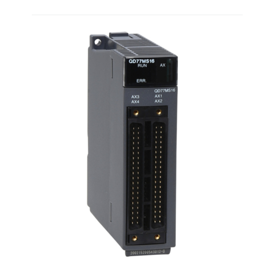
Page 140: Part Names
Part Names This section describes the part names of a CT input module. (1) Part names The following table lists the part names of a CT input module. Number Name Description Indicates the operating status of the CT input module. The module is operating normally. - Page 141 CHAPTER 7 SETTINGS AND THE PROCEDURE BEFORE OPERATION (2) Signal names of the terminal block The following shows signal names of the terminal block. Pin number Signal name...
-
Page 142: Wiring
Wiring This section describes the wiring precautions and module connection examples of a CT input module. 7.4.1 Wiring precautions External wiring that is less likely to be affected by noise is one of the conditions for a highly reliable system that fully utilizes the CT input module. -
Page 143: External Wiring
CHAPTER 7 SETTINGS AND THE PROCEDURE BEFORE OPERATION 7.4.2 External wiring The following describes the external wiring. Power side Detection line Detection line CT input module Terminal block Protection element Protection element Connection cable Load side ● Set Disable (1) to Conversion enable/disable setting (Un\G0) for unused channels. If Enable (0) is set to Conversion enable/disable setting (Un\G0) and the circuit between two terminals is kept open, an undefined digital value may be output. -
Page 144: Chapter 8 Various Settings
CHAPTER 8 VARIOUS SETTINGS This chapter describes the setting procedures of the CT input module. ● After writing the contents of the new module, parameter settings, and auto refresh settings into the CPU module, reset the CPU module and switch its status as STOP RUN STOP RUN, or turn off and on the power supply to activate the settings. -
Page 145: Switch Setting
CHAPTER 8 VARIOUS SETTINGS Switch Setting Set the operation mode. (1) Setting procedure Open the "Switch Setting" window. Project window [Intelligent Function Module] Module name [Switch Setting] Item Description Setting value Drive Mode Set the operation mode of the CT input •... -
Page 146: Parameter Setting
Parameter Setting Set the parameters for each channel. Setting parameters on the screen omits the parameter setting in a program. (1) Setting procedure Open the "Parameter" window. Start "Parameter". Project window [Intelligent Function Module] Module name [Parameter] Pull-down list type Text box type Double-click the item to change the setting, and input the setting value. - Page 147 CHAPTER 8 VARIOUS SETTINGS Item Setting value Reference 0: Enable Page 35, Conversion enable/disable setting 1: Disable (default value) Section 4.3 0: Sampling Processing (default value) 1: Time Average Averaging process setting 2: Count Average 3: Moving Average 4: Primary Delay Filter Time 40 to 5000ms (default value: 0) Page 36,...
- Page 148 Item Setting value Reference 0: Enable Peak current detection setting 1: Disable (default value) Peak current Page 44, detection setting Peak current detection time 10 to 10000ms (default value: 1000) Section 4.7 Peak current detection value 0 to 11999 (default value: 0) 0: Enable Logging enable/disable setting 1: Disable (default value)
-
Page 149: Auto Refresh
CHAPTER 8 VARIOUS SETTINGS Auto Refresh This function transfers data in the buffer memory to specified devices. Programming of reading/writing data is unnecessary. (1) Setting procedure Open the "Auto_Refresh" window. Start "Auto_Refresh". Project window [Intelligent Function Module] Module Name [Auto_Refresh] Click the item to set, and input the destination device for auto refresh. -
Page 150: Offset/Gain Setting
Offset/gain Setting When using a user range, configure the offset/gain setting with the following operations. When using a factory default range, the offset/gain setting is not required. The offset/gain setting can be configured from the following two types of operations. •... - Page 151 CHAPTER 8 VARIOUS SETTINGS Select a user range according to the type of the CT to be connected, and click the button. To use the input range set at the beginning of "Offset/Gain Setting", select "Not to Change" and click the button.
- Page 152 Input the gain value current to the target channel terminals, and click the button. Check that "Gain Status" changed to "Changed", and click the button. Click the button. The same input range must be selected for an offset setting and gain setting for the same channel.
-
Page 153: Setting From A Program
CHAPTER 8 VARIOUS SETTINGS 8.5.2 Setting from a program (1) Setting procedure The following is the procedure to configure the offset/gain setting using a sequence program. Start Set the target channels in Offset/gain setting mode Gain specification (Un\G23). Switch to the offset/gain setting mode. More than one channel can be set simultaneously on the condition that "0"... - Page 154 ● Configure the offset/gain setting in accordance with the actual use situation. ● Offset and gain values are recorded in the non-volatile memory in the CT input module by turning on then off User range write request (YA). The values are not deleted even after the power is turned off. If the values are written 26 times in succession, an error (error code: 162) occurs and the error code is stored in Latest error code (Un\G19) to prevent an improper write to non-volatile memory.
- Page 155 CHAPTER 8 VARIOUS SETTINGS (b) Switching the mode using the dedicated instruction (G(P).OFFGAN) This sequence program executes the following operations. • Switching the mode from the normal mode to the offset/gain setting mode using the dedicated instruction (G(P).OFFGAN) • Switching the channels for which the offset/gain settings are configured •...
- Page 156 (c) Switching the mode by setting Mode switching setting (Un\G158, Un\G159) and using Operating condition setting request (Y9) Set 4144 to Mode switching setting 1 (Un\G158). Set 0964 to Mode switching setting 2 (Un\G159). Turn on Operating condition setting request (Y9). Turn off Operating condition setting request (Y9).
-
Page 157: Chapter 9 Programming
CHAPTER 9 PROGRAMMING CHAPTER 9 PROGRAMMING This chapter describes the programming procedure and basic programs for the CT input module. Programming Procedure Create a program to execute digital conversion, according to the following procedure. Start Use the configuration function? Switch setting Page 156, Section 9.2, Page 165, Section 9.3 Switch setting, parameter setting, Page 156, Section 9.2, Page 165, Section 9.3... -
Page 158: When Using The Module In A Standard System Configuration
When Using the Module in a Standard System Configuration This section introduces program examples where the following system configuration and conditions apply. (1) System configuration QCPU QY10 (Y20 to Y2F) QX10 (X10 to X1F) CT input module (X/Y0 to X/YF) (2) Programming condition Digital output values are read in the following conditions. - Page 159 CHAPTER 9 PROGRAMMING (4) Initial setting (a) Channel setting Setting Item CH4 to CH8 Conversion enable/disable setting Enable Enable Enable Disable Sampling Primary Delay Sampling Averaging process setting Count Average Processing Filter Processing Average time/Average number of times/Moving average/Time constant 50 Times 100ms settings...
-
Page 160: Program Example When Using Parameters Of The Intelligent Function Module
9.2.1 Program example when using parameters of the intelligent function module (1) Device for user Device Description Conversion completed flag D1 (D11) CH1 Digital output value D2 (D12) CH2 Digital output value D3 (D13) CH3 Digital output value Warning output flag (Process alarm) Warning output flag (Rate alarm) Input signal error detection flag Peak current detection flag... - Page 161 CHAPTER 9 PROGRAMMING (2) Parameter setting Set the contents of initial settings to the parameters. Project window [Intelligent Function Module] [Q68CT] [Parameter]...
- Page 162 (3) Auto refresh setting Project window [Intelligent Function Module] [Q68CT] [Auto_Refresh] (4) Writing the parameters of intelligent function module Write the set parameters to the CPU module, and reset the CPU module or turn off then on the programmable controller power supply. [Online] [Write to PLC...] RESET...
- Page 163 CHAPTER 9 PROGRAMMING (5) Program example Read Conversion completed flag. Read CH1 Digital output value. Read CH2 Digital output value. Read CH3 Digital output value. Read Peak current detection flag. Processing when a peak current is detected for CH1 Peak current Processing when a peak current is detected detection Read Warning output flag...
-
Page 164: Program Example When Not Using Parameters Of The Intelligent Function Module
9.2.2 Program example when not using parameters of the intelligent function module (1) Device for user Device Description CH1 Digital output value CH2 Digital output value CH3 Digital output value CH1 Conversion completed flag CH2 Conversion completed flag CH3 Conversion completed flag M10 to M25 Warning output flag (Process alarm) M30 to M45... - Page 165 CHAPTER 9 PROGRAMMING (2) Program example Turn on Module READY check flag. Set CH1 Input range setting. Set CH2 Input range setting. Set CH3 Input range setting. Enable CH1 to CH3 Digital conversion. CH2 Average time/Average number of times/Moving average/Time constant settings CH3 Average time/Average number of times/Moving average/Time...
- Page 166 Read Conversion completed flag. Read CH1 Digital output value. Read CH2 Digital output value. Read CH3 Digital output value. Read Peak current detection flag. Processing when a peak current is detected for CH1 Peak current Processing when a peak current is detected detection Read Warning output flag (Process alarm).
-
Page 167: When Using The Module On The Remote I/O Network
CHAPTER 9 PROGRAMMING When Using the Module on the Remote I/O Network This section describes the system configuration and program examples of when the CT input module is used on a remote I/O network. For details on the MELSECNET/H remote I/O network, refer to the following. Q Corresponding MELSECNET/H Network System Reference Manual (Remote I/O network) (1) System configuration Remote master station... - Page 168 (3) Switch setting For the switch setting, refer to the procedure described in the following section. Page 169, Section 9.3 (6) (4) Initial setting (a) Channel setting Setting Item CH4 to CH8 Conversion enable/disable setting Enable Enable Enable Disable Sampling Primary Delay Sampling Averaging process setting...
- Page 169 CHAPTER 9 PROGRAMMING (5) Setting on the master station Create a project on GX Works2. Select "QCPU (Q mode)" for "Series", and select the CPU module used for "Type". [Project] [New...] Display the network parameter setting window, and configure the setting as follows. Project window [Parameter] [Network Parameter]...
- Page 170 Display the network range assignment setting window, and configure the setting as follows. Project window [Parameter] [Network Parameter] [Ethernet/CC IE/MELSECNET] button Project window [Parameter] [Network Parameter] [Ethernet/CC IE/MELSECNET] button "Switch Screens" "XY Setting"...
- Page 171 CHAPTER 9 PROGRAMMING Display the refresh parameter setting window, and configure the setting as follows. Project window [Parameter] [Network Parameter] [Ethernet/CC IE/MELSECNET] button Write the set parameters to the CPU module on the master station. Then reset the CPU module or turn off and on the power supply of the programmable controller.
- Page 172 Add the Q68CT to the project on GX Works2. Project window [Intelligent Function Module] Right-click [New Module...] Display the Q68CT "Switch Setting" window, and configure the setting as follows. Project window [Intelligent Function Module] [Q68CT] [Switch Setting]...
- Page 173 CHAPTER 9 PROGRAMMING Display the Q68CT initial setting window, and configure the setting as follows. When creating a program without using parameters of an intelligent function module, skip this procedure. Project window [Intelligent Function Module] [Q68CT] [Parameter]...
- Page 174 Display the Q68CT auto refresh setting window, and configure the setting as follows. When creating a program without using parameters of an intelligent function module, skip this procedure. Project window [Intelligent Function Module] [Q68CT] [Auto_Refresh] Write the set parameters to the remote I/O module, and reset the remote I/O module. [Online] [Write to PLC...] RESET...
-
Page 175: Program Example When Using Parameters Of The Intelligent Function Module
CHAPTER 9 PROGRAMMING 9.3.1 Program example when using parameters of the intelligent function module (1) Device for user Device Description W1000 Conversion completed flag W1001 (D11) CH1 Digital output value W1002 (D12) CH2 Digital output value W1003 (D13) CH3 Digital output value W1006 Warning output flag (Process alarm) W1007... - Page 176 (2) Program example Read Conversion completed flag. Read CH1 Digital output value. Read CH2 Digital output value. Read CH3 Digital output value. Read Peak current detection flag. Processing when a peak current is detected for CH1 Peak current Processing when a peak current is detected detection Read Warning output flag (Process alarm).
-
Page 177: Program Example When Not Using Parameters Of The Intelligent Function Module
CHAPTER 9 PROGRAMMING 9.3.2 Program example when not using parameters of the intelligent function module (1) Device for user Device Description D1000 to D1326 Device for initial value setting D2010 Conversion completed flag D2011 (D11) CH1 Digital output value D2012 (D12) CH2 Digital output value D2013 (D13) CH3 Digital output value... - Page 178 Device Description SW78 Parameter communication status of each station T100 to T104 Interlock for own station and other stations (2) Program example Check master station baton pass status. Check master station data link status. Check remote I/O station baton pass status. Check remote I/O station data link status.
- Page 179 CHAPTER 9 PROGRAMMING Set CH1 Input range setting. Set CH2 Input range setting. Set CH3 Input range setting. Enable CH1 to CH3 Digital conversion. CH2 Average time/Average number of times/Moving average/Time constant settings CH3 Average time/Average number of times/Moving average/Time constant settings Set CH1 to CH3 averaging process setting.
- Page 180 Write to the buffer memory. Turn on Operating condition setting request. Turn off Operating condition setting request. Read CH1 Digital output value. Read CH2 Digital output value. Read CH3 Digital output value. Read Conversion completed flag. Read Peak current detection flag. Processing when a peak current is detected for CH1 Peak current Processing when a peak current is detected...
- Page 181 CHAPTER 9 PROGRAMMING Processing when an alert occurs for Processing when an alert occurs CH3 Rate alarm lower limit value Read Input signal error detection flag. Processing when CH1 Input signal Processing when an input signal error is detected error Turn on input signal error reset signal.
-
Page 182: Chapter 10 Online Module Change
CHAPTER 10 ONLINE MODULE CHANGE This chapter describes the online module change procedure. In this manual, the procedure is explained using GX Works2 When performing an online module change, carefully read the following. • QCPU User's Manual (Hardware Design, Maintenance and Inspection) 10.1 Precautions on Online Module Change This section lists precautions on an online module change. -
Page 183: Conditions For Online Module Change
CHAPTER 10 ONLINE MODULE CHANGE 10.2 Conditions for Online Module Change To perform an online module change, satisfy the following conditions. Remark The function version of the first released CT input module is C, and the CT input module supports the online module change. (1) CPU module A Process CPU or Redundant CPU is required. -
Page 184: Online Module Change Operations
10.3 Online Module Change Operations The following table explains the operations for an online module change. : Executed ×: Not executed Operation of the CPU module Operation of User operation the CT input module FROM/TO Dedicated Device Parameter refresh instructions instruction test setting... -
Page 185: Online Module Change Procedure
CHAPTER 10 ONLINE MODULE CHANGE 10.4 Online Module Change Procedure This section and the following sections describe two online module change procedures: setting parameters using the configuration function and setting parameters using a sequence program. The same procedures are applied to GX Developer. - Page 186 (2) Procedure The following flow shows the online module change procedure. Start Stop the operation. Remove the module. Mount a new module. Check the operation. Resume the control.
-
Page 187: When A Factory Default Range Is Used And Parameters Are Set Using The Configuration
CHAPTER 10 ONLINE MODULE CHANGE 10.5 When a Factory Default Range Is Used and Parameters Are Set Using the Configuration Function (1) Stopping operation Open the "Device/Buffer Memory Batch Monitor" window. [Online] [Monitor] [Device/Buffer Memory Batch] Enter and display the buffer memory address of Conversion enable/disable setting (Un\G0). - Page 188 (2) Removing a module Open the "System Monitor" window. [Diagnostics] [Online Module Change...] Select "Online module change" under the "Mode" field and double-click the module name to be changed online. Click the button to enable a module change. When the following error window appears, click the button and perform the operation described in Page 187, Section 10.5 (3).
- Page 189 CHAPTER 10 ONLINE MODULE CHANGE (3) Mounting a new module Mount a new module in the same slot and install the terminal block. After mounting the module, click the button and make sure that the RUN LED is lit. Module READY (X0) remains off. (4) Checking operation To check the operation, click the button to cancel the control start.
- Page 190 (From the previous page) Click the button to close the "System Monitor" window. Open the "Device/Buffer Memory Batch Monitor" window. [Online] [Monitor] [Device/Buffer Memory Batch] Monitor Conversion enable/disable setting (Un\G0) to check if the channel to be used is set to Enable (0).
- Page 191 CHAPTER 10 ONLINE MODULE CHANGE (5) Resuming operation Open the "Online Module Change" window again. [Diagnostics] [Online Module Change...] Click the button on the appeared window to resume control. Module READY (X0) turns on. The online module change is complete.
- Page 192 10.6 When a Factory Default Range Is Used and Parameters Are Set Using a Sequence Program (1) Stopping operation Open the "Device/Buffer Memory Batch Monitor" window. [Online] [Monitor] [Device/Buffer Memory Batch] When using GX Developer, open the "Device test" window. [Online] [Debug] [Device test...]...
- Page 193 CHAPTER 10 ONLINE MODULE CHANGE (2) Removing a module Open the "System Monitor" window. [Diagnostics] [Online Module Change...] Select "Online Module Change" under the "Mode" field and double-click the module name to be changed online. Click the button to enable a module change.
- Page 194 (3) Mounting a new module Mount a new module in the same slot and install the terminal block. After mounting the module, click the button and make sure that the RUN LED is lit. Module READY (X0) remains off. (4) Checking operation To check the operation, click the button to cancel the control start.
- Page 195 CHAPTER 10 ONLINE MODULE CHANGE (From the previous page) Click the button to close the "System Monitor" window. Open the "Device/Buffer Memory Batch Monitor" window. [Online] [Monitor] [Device/Buffer Memory Batch] When using GX Developer, open the "Device test" window.
- Page 196 (From the previous page) Set Conversion enable/disable setting (Un\G0) to Enable (0) for the channel used. Turn on Operating condition setting request (Y9). Check that Operating condition setting completed flag (X9) turns off, then turn off Operating condition setting request (Y9). Monitor CH...
- Page 197 CHAPTER 10 ONLINE MODULE CHANGE (5) Resuming operation Open the "Online Module Change" window again. [Diagnostics] [Online Module Change...] Click the button on the appeared window to resume control. Module READY (X0) turns on. The online module change is complete.
-
Page 198: When A User Range Is Used And Parameters Are Set Using The Configuration Function
10.7 When a User Range Is Used and Parameters Are Set Using the Configuration Function (with Another System) (1) Stopping operation Open the "Device/Buffer Memory Batch Monitor" window. [Online] [Monitor] [Device/Buffer Memory Batch] Enter and display the buffer memory address of Conversion enable/disable setting (Un\G0). - Page 199 CHAPTER 10 ONLINE MODULE CHANGE (2) Removing a module Open the "System Monitor" window. [Diagnostics] [Online Module Change...] Select "Online Module Change" under the "Mode" field and double-click the module name to be changed online. Click the button to enable a module change.
- Page 200 (3) Mounting a new module Mount the removed module and new module to the other system. Using the G(P).OGLOAD instruction, save the offset/gain setting values in the user range from the removed module to the CPU device. Refer to Page 236, Appendix 1.2 for the G(P).OGLOAD instruction.
- Page 201 CHAPTER 10 ONLINE MODULE CHANGE (From the previous page) Click the button to leave the "Online Module Change" mode. Click the button to close the "System Monitor" window. Open the "Device/Buffer Memory Batch Monitor" window. [Online] [Monitor] [Device/Buffer Memory Batch] Monitor Conversion enable/disable setting (Un\G0) to check if the channel to be used is set to Enable...
- Page 202 (5) Resuming operation Open the "Online Module Change" window again. [Diagnostics] [Online Module Change...] Click the button on the appeared window to resume control. Module READY (X0) turns on. The online module change is complete.
-
Page 203: When A User Range Is Used And Parameters Are Set Using A Sequence Program
CHAPTER 10 ONLINE MODULE CHANGE 10.8 When a User Range Is Used and Parameters Are Set Using a Sequence Program (with Another System) (1) Stopping operation Open the "Device/Buffer Memory Batch Monitor" window. [Online] [Monitor] [Device/Buffer Memory Batch] When using GX Developer, open the "Device test" window. - Page 204 (2) Removing a module Open the "System Monitor" window. [Diagnostics] [Online Module Change...] Select "Online Module Change" under the "Mode" field and double-click the module name to be changed online. Click the button to enable a module change. When the following error window appears, click the button and perform the operation described in Page 203, Section 10.8 (3).
- Page 205 CHAPTER 10 ONLINE MODULE CHANGE (3) Mounting a new module Mount the removed module and new module to the other system. Using the G(P).OGLOAD instruction, save the offset/gain setting values in the user range from the removed module to the CPU device. Refer to Page 236, Appendix 1.2 for the G(P).OGLOAD instruction.
- Page 206 (From the previous page) Click the button to leave the "Online Module Change" mode. Click the button to close the "System Monitor" window. Open the "Device/Buffer Memory Batch Monitor" window. [Online] [Monitor] [Device/Buffer Memory Batch] When using GX Developer, open the "Device test" window.
- Page 207 CHAPTER 10 ONLINE MODULE CHANGE (From the previous page) Set Conversion enable/disable setting (Un\G0) to Enable (0) for the channel used. Turn on Operating condition setting request (Y9). Check that Operating condition setting completed flag (X9) turns off, then turn off Operating condition setting request (Y9).
- Page 208 (5) Resuming operation Open the "Online Module Change" window again. [Diagnostics] [Online Module Change...] Click the button on the appeared window to resume control. Module READY (X0) turns on. The online module change is complete.
-
Page 209: When A User Range Is Used And Parameters Are Set Using The Configuration Function
CHAPTER 10 ONLINE MODULE CHANGE 10.9 When a User Range Is Used and Parameters Are Set Using the Configuration Function (without Another System) (1) Stopping operation Open the "Device/Buffer Memory Batch Monitor" window. [Online] [Monitor] [Device/Buffer Memory Batch] Enter and display the buffer memory address of Conversion enable/disable setting (Un\G0). - Page 210 (2) Removing a module Open the "System Monitor" window. [Diagnostics] [Online Module Change...] Select "Online Module Change" under the "Mode" field and double-click the module name to be changed online. Click the button to enable a module change. When the following error window appears, click the button and perform the operation described in Page 209, Section 10.9 (3).
- Page 211 CHAPTER 10 ONLINE MODULE CHANGE (3) Mounting a new module Mount a new module in the same slot and install the terminal block. After mounting the module, click the button and make sure that the RUN LED is lit. Module READY (X0) remains off. (4) Checking operation To check the operation, click the button to cancel the control start.
- Page 212 (From the previous page) Click the button to close the "System Monitor" window. Open the "Device/Buffer Memory Batch Monitor" window. [Online] [Monitor] [Device/Buffer Memory Batch] Display the address of the prerecorded buffer memory area and select it. Then click the button.
- Page 213 CHAPTER 10 ONLINE MODULE CHANGE (From the previous page) Set the prerecorded data to the buffer memory. Turn User range write request (YA) from off to on to restore the offset/gain setting value in the user range to the module. After confirming that Offset/gain setting mode flag (XA) is on, turn off User range write request (YA).
- Page 214 (5) Resuming operation Open the "Online Module Change" window again. [Diagnostics] [Online Module Change...] Click the button on the appeared window to resume control. Module READY (X0) turns on. The online module change is complete.
-
Page 215: When A User Range Is Used And Parameters Are Set Using A Sequence Program
CHAPTER 10 ONLINE MODULE CHANGE 10.10 When a User Range Is Used and Parameters Are Set Using a Sequence Program (without Another System) (1) Stopping operation Open the "Device/Buffer Memory Batch Monitor" window. [Online] [Monitor] [Device/Buffer Memory Batch] When using GX Developer, open the "Device test" window. - Page 216 ● If the buffer memory values are improper compared to the reference table, the offset/gain values cannot be saved and restored. Before resuming the control, configure an offset/gain setting according to the flowchart ( Page 151, Section 8.5.2). Note that if module control is resumed without offset/gain setting being made, operation will be performed with the default values.
- Page 217 CHAPTER 10 ONLINE MODULE CHANGE (2) Removing a module Open the "System Monitor" window. [Diagnostics] [Online Module Change...] Select "Online Module Change" under the "Mode" field and double-click the module name to be changed online. Click the button to enable a module change.
- Page 218 (3) Mounting a new module Mount a new module in the same slot and install the terminal block. After mounting the module, click the button and make sure that the RUN LED is lit. Module READY (X0) remains off. (4) Checking operation To check the operation, click the button to cancel the control start.
- Page 219 CHAPTER 10 ONLINE MODULE CHANGE (From the previous page) Click the button to close the "System Monitor" window. Open the "Device/Buffer Memory Batch Monitor" window. [Online] [Monitor] [Device/Buffer Memory Batch] When using GX Developer, open the "Device test" window.
- Page 220 (From the previous page) Set the prerecorded data to the buffer memory. Turn User range write request (YA) from off to on to restore the offset/gain setting value in the user range to the module. After confirming that Offset/gain setting mode flag (XA) is on, turn off User range write request (YA).
- Page 221 CHAPTER 10 ONLINE MODULE CHANGE (5) Resuming operation Open the "Online Module Change" window again. [Diagnostics] [Online Module Change...] Click the button on the appeared window to resume control. Module READY (X0) turns on. The online module change is complete.
-
Page 222: Range Reference Table
10.11 Range Reference Table This section lists range reference used for an online module change. (1) CH1 Factory default setting offset value (Un\G202) to CH8 User range setting gain value (Un\G233) Address (Decimal) Reference Description value (Hexadecimal) 00000000 Factory default setting offset value 00002710 Factory default setting gain value 00000000... -
Page 223: Chapter 11 Troubleshooting
CHAPTER 11 TROUBLESHOOTING CHAPTER 11 TROUBLESHOOTING This chapter describes errors that may occur in a CT input module and troubleshooting for them. 11.1 Error Code List This section describes error codes that occur in a CT input module. (1) Error code checking method The error codes that occur in a CT input module can be checked by the following. - Page 224 (a) Checking on the "Module's Detailed Information" window Follow the following procedure. [Diagnostics] [System Monitor...] Select the CT input module in "Main Base", and click the button. "Module's Detailed Information" of the CT input module is displayed. (b) Checking in Latest error code (Un\G19) Follow the following procedure.
- Page 225 CHAPTER 11 TROUBLESHOOTING (c) Checking through the module error collection function The errors occurred in a CT input module are saved in the CPU module through the module error collection function. Therefore, the error details are kept unerased even if the power is turned off or the CPU module is reset. •...
- Page 226 (2) Error code list If the following errors occur on the CT input module while data is written to or read from the CPU module, the corresponding error code below is stored in Latest error code (Un\G19). The error is reported to the CPU module also. Error code Description and the error cause Action...
- Page 227 CHAPTER 11 TROUBLESHOOTING Error code Description and the error cause Action (decimal) • Execute the G(P).OGLOAD and G(P).OGSTOR • The G(P).OGSTOR instruction has been executed toward a instructions to the same module. module different from the one on which the G(P).OGLOAD •...
- Page 228 Error code Description and the error cause Action (decimal) CH Dropout value (Un\G162 to Un\G169) is outside the range Set CH Dropout value (Un\G162 to Un\G169) in the of 1 to 10000. 39 range of 1 to 10000. The channel where the error has occurred fits in . When a user range is set or restored, the offset value is equal to Set values so that they meet the following condition: or greater than the gain value.
- Page 229 CHAPTER 11 TROUBLESHOOTING Error code Description and the error cause Action (decimal) Set CH Logging cycle setting value (Un\G1032 to Un\G1039) and CH Logging cycle unit setting (Un\G1040 to Un\G1047) so that the logging cycle is The set logging cycle is shorter than the update cycle of the equal to or longer than the update cycle of the logged logged value (digital output value or scaling value).
-
Page 230: Alarm Code List
11.2 Alarm Code List This section describes alarm codes that occur in a CT input module. (1) Alarm code checking method Alarms occurred in the CT input module can be checked by the same methods as those for errors. ( Page 221, Section 11.1 (1)) (2) Alarm code list... -
Page 231: Troubleshooting
CHAPTER 11 TROUBLESHOOTING 11.3 Troubleshooting 11.3.1 When the RUN LED flashes or turns off (1) When flashing Check item Action • Set the operation mode in the intelligent function module switch setting to the normal mode. Or reset the switch 4 in the intelligent function module switch setting to the normal mode. -
Page 232: When The Alm Led Turns On Or Flashes
11.3.3 When the ALM LED turns on or flashes (1) When on Check item Action Check Warning output flag (Process alarm) (Un\G50) or Warning Is there any alarm output? output flag (Rate alarm) (Un\G51). (2) When flashing Check item Action Is there any input signal error? Check Input signal error detection flag (Un\G49). -
Page 233: When Conversion Completed Flag Does Not Turn On In The Normal Mode
CHAPTER 11 TROUBLESHOOTING 11.3.5 When Conversion completed flag does not turn on in the normal mode Check item Action Is there any input signal error? Check Input signal error detection flag (Un\G49). -
Page 234: Checking The Ct Input Module Status On Gx Works2 System Monitor
11.4 Checking the CT Input Module Status on GX Works2 System Monitor To check the LED status or the setting status of the intelligent function module switch setting, select the H/W information of the CT input module on the system monitor of GX Works2. (1) Hardware LED information The LED status is displayed. -
Page 235: Appendices
APPENDICES APPENDICES Appendix 1 Dedicated Instruction (1) Dedicated instruction The following table lists dedicated instructions that can be used in a CT input module. Instruction Description • This instruction switches the operation mode to the offset/gain setting mode. G(P).OFFGAN • This instruction switches the operation mode to the normal mode. G(P).OGLOAD This instruction reads out the offset/gain set values in a user range setting to the CPU module. -
Page 236: Appendix 1.1 G(P).Offgan
Appendix 1.1 G(P).OFFGAN Command G.OFFGAN G.OFFGAN Command GP.OFFGAN GP.OFFGAN Internal device J\ Constant Setting R, ZR U\G Others data K, H, Word Word (1) Setting data Device Description Setting range Data type 0 to FE Start I/O number of the module BIN 16 bits Mode change 0: changed to the normal mode... - Page 237 APPENDICES (4) Program example The following shows the sequence program of the CT input module, installed in I/O number X/Y00 to X/Y0F, with the following conditions. • Turning on M10 switches the operation mode of the CT input module to the offset/gain setting mode •...
-
Page 238: Appendix 1.2 G(P).Ogload
Appendix 1.2 G(P).OGLOAD Command G.OGLOAD G.OGLOAD Command GP.OGLOAD GP.OGLOAD Internal device J\ Constant Setting R, ZR U\G Others data K, H, Word Word (1) Setting data Device Description Setting range Data type 0 to FE Start I/O number of the module BIN 16 bits Within the range Start number of the device where control data is stored... - Page 239 APPENDICES (2) Control data Device Item Setting data Setting range Set by System area The status on instruction completion is stored. Completion status 0: normal completion System Other than 0: error completion (error code) ...
- Page 240 Device Item Setting data Setting range Set by CH8 User range setting offset value System CH8 User range setting gain value System These control data are unnecessary to be set. When they are set, offset/gain setting values are not correctly read out. (3) Functions •...
- Page 241 APPENDICES (5) Program example The following shows the sequence program of the CT input module, installed in I/O number X/Y00 to X/Y0F, with the following conditions. • Turning on M11 reads out the offset/gain setting value of the CT input module. Dedicated instruction (GP.OGLOAD) Processing when an instruction execution is failed...
-
Page 242: Appendix 1.3 G(P).Ogstor
Appendix 1.3 G(P).OGSTOR Command G.OGSTOR G.OGSTOR Command GP.OGSTOR GP.OGSTOR Internal device J\ Constant Setting R, ZR U\G Others data K, H, Word Word (1) Setting data Device Description Setting range Data type 0 to FE Start I/O number of the module BIN 16 bits Within the range Start number of the device where control data is stored... - Page 243 APPENDICES (2) Control data Device Item Setting data Setting range Set by System area The status on instruction completion is stored. Completion status 0: normal completion System Other than 0: error completion (error code) ...
- Page 244 Device Item Setting data Setting range Set by CH8 User range setting offset value System CH8 User range setting gain value System (3) Functions • This instruction restores the offset/gain set values in a user range setting to the CT input module. •...
- Page 245 APPENDICES (5) Program example The following shows the sequence program of the CT input module, installed in I/O number X/Y00 to X/Y0F, with the following conditions. • Turning off M11 writes the offset/gain setting value to the CT input module. Dedicated instruction (GP.OGSTOR) Processing when an instruction execution...
-
Page 246: Appendix 2 When Using Gx Developer
Appendix 2 When Using GX Developer This chapter describes the operating procedure of GX Developer. When GX Developer is used, perform the initial setting and auto refresh in the sequence program. • Program example when not using parameters of the intelligent function module ( Page 162, Section 9.2.2 and Page 175, Section 9.3.2) (1) Applicable software packages... - Page 247 APPENDICES (2) Intelligent function module switch setting Configure the setting on "Switch setting" in "PLC parameter". Parameter [PLC parameter] [I/O assignment] Click the button. Select "HEX.". Item Setting range Switch 1 0: Fixed (blank) Switch 2 0: Fixed (blank) Switch 3 0: Fixed (blank) H *1 Fixed to 000...
-
Page 248: Appendix 3 External Dimensions
Appendix 3 External Dimensions The following figure shows the external dimensions of a CT input module. 27.4 (Unit: mm) - Page 249 APPENDICES Memo...
-
Page 250: Index
INDEX CH Process alarm lower lower limit value (Un\G86, Un\G90, Un\G94, Un\G98, Un\G102, Un\G106, ....... 29 Accuracy . - Page 251 ......86 Error flag (XF) ..... . . 72 Error history function .
-
Page 252: Revisions
Japanese manual version SH-081032-C This manual confers no industrial property rights or any rights of any other kind, nor does it confer any patent licenses. Mitsubishi Electric Corporation cannot be held responsible for any problems involving industrial property rights which may occur as a result of using the contents noted in this manual. -
Page 253: Warranty
WARRANTY Please confirm the following product warranty details before using this product. 1. Gratis Warranty Term and Gratis Warranty Range If any faults or defects (hereinafter "Failure") found to be the responsibility of Mitsubishi occurs during use of the product within the gratis warranty term, the product shall be repaired at no cost via the sales representative or Mitsubishi Service Company. - Page 254 Ethernet is a registered trademark of Fuji Xerox Corporation in Japan. The SD and SDHC logos are trademarks of SD-3C, LLC. The company names, system names and product names mentioned in this manual are either registered trademarks or trademarks of their respective companies. ...
- Page 256 SH(NA)-081033ENG-B(1605)MEE MODEL: Q68CT-U-E MODEL CODE: 13JZ66 HEAD OFFICE : TOKYO BUILDING, 2-7-3 MARUNOUCHI, CHIYODA-KU, TOKYO 100-8310, JAPAN NAGOYA WORKS : 1-14 , YADA-MINAMI 5-CHOME , HIGASHI-KU, NAGOYA , JAPAN When exported from Japan, this manual does not require application to the Ministry of Economy, Trade and Industry for service transaction permission.
Need help?
Do you have a question about the MELSEC-Q series and is the answer not in the manual?
Questions and answers