Table of Contents
Advertisement
Quick Links
TresCon P04-P
TresCon
Ser.-Nr. 00110010
WTW 82362 Weilheim Made in Germany
TresCon PO4-P
Ablauf
Pumpschlauch Standard/Probe
blau / blau / blau
Pumpschlauch Reagenz
orange / gelb / orange
P1
P2
Thermoblock
blau
grün
rot
P3
blue
green
red
Pump Tube Standard/Sample
blue / blue / blue
V2
V4
V1
V3
Pump Tube Reagent
orange / yellow / orange
blau
gelb
orange
grün
blue
yellow
orange
green
Sample
Probe
Reinigungslösung
H O dest.
H O dest.
2
Standard B
Standard B
Reagenz
Reagent
Cleaning Solution
2
OPERATING MANUAL
ba43134e08 05/2017
Advertisement
Table of Contents

Subscribe to Our Youtube Channel
Related Manuals for wtw TresCon UNO A111


Summary of Contents for wtw TresCon UNO A111
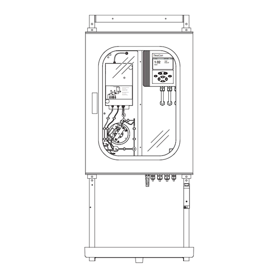
- Page 1 OPERATING MANUAL ba43134e08 05/2017 TresCon P04-P TresCon Ser.-Nr. 00110010 WTW 82362 Weilheim Made in Germany TresCon PO4-P Ablauf Pumpschlauch Standard/Probe blau / blau / blau Pumpschlauch Reagenz orange / gelb / orange Thermoblock blau grün blue green Pump Tube Standard/Sample...
- Page 2 TresCon UNO © Copyright 2017 Xylem Analytics Germany GmbH Printed in Germany. ba43134e08 05/2017...
-
Page 3: Table Of Contents
TresCon UNO List of contents TresCon UNO - List of contents Overview ........1-1 About this operating manual . - Page 4 Inhaltsverzeichnis TresCon UNO Option: Permeate switch ......3-29 3.7.1 Installing the permeate switch ... . .3-30 Connecting the supply of consumables .
- Page 5 TresCon UNO Inhaltsverzeichnis Modem ........5-66 5.6.1 General .
- Page 6 Inhaltsverzeichnis TresCon UNO Abbreviations ....... . .9-1 Index ........9-1 0 - 4 ba43134e08 05/2017...
-
Page 7: Overview
TresCon UNO Overview Overview The first chapter contains the following information: Structure and contents of this operating manual Structure and function of TresCon UNO Please read the following section 1.1 A BOUT THIS OPERATING MANUAL before starting to work with the TresCon UNO. You will discover how to rapidly find the information that you require. -
Page 8: Structure And Function
TresCon UNO Structure and function 1.2.1 Structure Overview of the main components TresCon P04-P Ser.-Nr. 00110010 TresCon WTW 82362 Weilheim Made in Germany TresCon PO4-P Ablauf Pumpschlauch Standard/Probe blau / blau / blau Pumpschlauch Reagenz orange / gelb / orange Thermoblock blau grün... -
Page 9: Mounting Element With Tray Of Reagents
TresCon UNO Overview 1.2.2 Mounting element with tray of reagents The mounting element is made of steel profiles. It is ready for wall mounting and carries the TresCon UNO enclosure together with the tray of reagents in the correct distance below. On the tray of reagents, the reagents for the analyzer module are pro- vided. -
Page 10: Mounting Frame
1.2.5 Analyzer module TresCon UNO can be equipped with the following modules: TresCon NH4-N for measuring ammonium - nitrogen (TresCon UNO A111) TresCon NO2-N for measuring nitrite - nitrogen (TresCon UNO N511) TresCon NOx-N for measuring nitrate/nitrite - nitrogen (TresCon UNO N211) ... -
Page 11: Controller
TresCon UNO Overview 1.2.7 Controller The controller is the control and operating unit of the instrument. It is equipped with a planar display that also enables the graphical repre- sentation of measured values such as daily and weekly load diagrams. The operation of is menu-driven via the display and keys in the dialog system. - Page 12 Overview TresCon UNO Display Display Record The comprehensive record functions enable data records to be compiled (analyzer module-related, time-dependent, etc...) and the corresponding interval to be individually optimized. Report The report function enables the limiting con- ditions and operating states to be traced in case of malfunction.
-
Page 13: Function
TresCon UNO Overview Function 1.3.1 General Hardware The controller and analyzer module have a microprocessor with speci- fic program parts of their own. The controller and analyzer module communicate with one another via a data bus. The processor in the controller controls the analyzer module. - Page 14 Overview TresCon UNO Features TresCon UNO combines the proven features of the WTW analyzers with the additional new developments: AutoThermControl: Temperature control of the analyzer module. AutoFlowControl: Pressure measurement for the identification of clogging, leakage and levels of reagents.
-
Page 15: Safety
TresCon UNO Safety Safety This operating manual contains basic instructions that you must follow during the commissioning, operation and maintenance of the TresCon UNO. Consequently, the operator must read this operating manual before working with the instrument. The analyzer modules are delivered with a separate component opera- ting manual. -
Page 16: Authorized Operation
Safety TresCon UNO Special user The following installation activities may only be performed by a quali- qualifications fied electrician: All work that requires to open the mounting frame in the enclosure, especially installing electric circuits that conduct mains voltage to the terminal strip of TresCon UNO Authorized operation The authorized operation of TresCon UNO consists of... - Page 17 TresCon UNO Safety Technical condition It is the responsibility of the operator to continuously observe the over- all technical condition (externally recognizable deficits and damage as well as alterations to the operational behavior) of the analyzer. Safe operation If safe operation is not possible, take the instrument out of service and secure it against inadvertent operation! Safe operation is no longer possible if components: ...
- Page 18 Safety TresCon UNO 2 - 4 ba43134e08 05/2017...
-
Page 19: Installation
TresCon UNO Installation Installation Scope of delivery The following articles are included within the scope of delivery: TresCon UNO basic instrument, equipped with analyzer module Mounting element for wall mounting Tray of reagents Overflow vessel with tubing material ... -
Page 20: Installing The Trescon Uno
Installation TresCon UNO Installing the TresCon UNO Attention The mounting, installation and setting up of the instrument must only be performed by trained specialist personnel after they have carefully stu- died this operating manual. The manufacturer reserves the right to reject any warranty claims in case of noncompliance. - Page 21 TresCon UNO Installation Assemble the mounting element (Fig. 3-1). To do so, connect the two mounting angles (pos. 1) to the two cross members (pos. 2). Use the screws that are screwed in the thread drillings of the mounting angles. Fix the mounting element to the wall provisionally, using the drillings (pos.
- Page 22 Installation TresCon UNO (4x) Fig. 3-3 Fixing the enclosure on the mounting element Mounting the tray of Screw the tray of reagents (pos. 6 in Fig. 3-4) to the mounting reagents element through the drillings in the tray bottom, using the screws supplied (pos.
- Page 23 TresCon UNO Installation Mounting the overflow The scope of delivery of TresCon UNO contains a simple overflow ves- vessel sel. (sample supply) A single overflow vessel is used for each catch location. With the aid of the retrofit option, permeate switch, TresCon UNO can deal with two catch locations.
- Page 24 Installation TresCon UNO Mounting the drain set Assemble the parts of the drain set according to Fig. 3-6 and connect them to the drain opening on the enclosure bottom of TresCon UNO. Fig. 3-6 TresCon UNO with HT drain set Plug the connection piece into the second straight HT piece according to Fig.
- Page 25 TresCon UNO Installation Insert both free ends of the drain set in a suitable, pressure-free drain. Connecting the overflow Connect the overflow vessel to the following connectors (see vessel Fig. 3-8): – Connect the sample or permeate tube (black tube, inner dia- meter = 6 mm) to the front connection piece of the overflow vessel.
-
Page 26: Connection To The Voltage Supply
Installation TresCon UNO Connection to the voltage supply Attention The values of the mains power socket must agree with the specifica- tions in the chapter 7 T of this operating manual. ECHNICAL DATA Plug the power cable into an easily accessible mains socket. Attention Read the section chapter 4 I before switching on... -
Page 27: Further Electrical Connections (Optional)
TresCon UNO Installation Further electrical connections (optional) 3.5.1 Overview TresCon UNO provides the following connections: twelve relay contacts three connections for valve control three recorder outputs one RS485 connection two RS232 connections (1x via terminals, 1x via D-SUB plug) The connections are on the terminal strip in the TresCon UNO enclo- sure. -
Page 28: Connecting Lines To The Terminal Strip
Installation TresCon UNO 3.5.2 Connecting lines to the terminal strip Warning If external electrical circuits that are subject to the danger of physical contact are incorrectly connected to the relay contacts, there may be a danger of life threatening electric shock.Electrical circuits are regarded to be subject to the danger of physical contact when there are voltages higher than the Safety Extra Low Voltage SELV according to IEC 60449. - Page 29 Attention The mounting frame may only be opened by a qualified electrician. TresCon P04-P Ser.-Nr. 00110010 TresCon WTW 82362 Weilheim Made in Germany TresCon PO4-P Ablauf Pumpschlauch Standard/Probe blau / blau / blau Pumpschlauch Reagenz orange / gelb / orange...
- Page 30 Installation TresCon UNO Open the mounting frame: – First remove the two lower screws (pos. 1 in Fig. 3-10). – Then remove the two upper screws (pos. 2). When remov- ing the last screw, support the mounting frame (pos. 3) with the hand that is free.
- Page 31 TresCon UNO Installation Safety separating plate Cable duct Cable tie with adhesive base (3x) Cable glands Fig. 3-12 Leading cables to the terminal strip (viewing the analyzer from the front) Lead the cable(s) to the terminal strip (Fig. 3-12). When doing so, separate voltages subject to the danger of physical contact from Safety Extra Low Voltage SELV: –...
-
Page 32: Relays
Installation TresCon UNO TresCon P04-P Ser.-Nr. 00110010 TresCon WTW 82362 Weilheim Made in Germany TresCon PO4-P Ablauf Pumpschlauch Standard/Probe blau / blau / blau Pumpschlauch Reagenz orange / gelb / orange Thermoblock blau grün blue green Pump Tube Standard/Sample blue / blue / blue... - Page 33 TresCon UNO Installation Switching voltages and switching currents on the relay contacts must not exceed the values specified in chapter 7 T ECHNICAL DATA Protect electrical circuits against currents that are too high with an electrical fuse. The mounting frame may only be opened after the installation if all external voltages have been previously switched off.
-
Page 34: Valve Control
Installation TresCon UNO RCD protective circuit Example of the circuit: I: Highest switching power at the relay U: Maximum swit- Contact ching voltage : Load current Load I Fig. 3-14 RCD protective circuit for inductive load Component dimensioning: · ⋅ 0 1μF I --- - ------------------------- -... -
Page 35: Recorder Outputs
TresCon UNO Installation Assignment terminal strip X2 valves Fig. 3-15 Terminals of the valve control 3.5.5 Recorder outputs Assignment terminal strip X2 recorders Fig. 3-16 Terminals of the recorder outputs Note The setting of the recorder is described in 5.4 R SECTION ECORDER from... -
Page 36: Digital Interfaces: General
Installation TresCon UNO 3.5.6 Digital interfaces: General The analyzer has two serial interfaces: RS485 and RS232 printer (serial) Controller TresCon UNO modem Fig. 3-17 Communication options of the serial interfaces Note The setting of the interface parameters and the modem initialization is performed in the software via the controller. -
Page 37: Rs485
TresCon UNO Installation 3.5.7 RS485 This interface can be used in either Slave or Master mode. Assignment terminal strip X2 RS485 Fig. 3-18 Terminals of the RS485 interface Note The setting of the interface parameters is described in section 5.5.2 RS485 (S and section 5.5.3 RS485 LAVE INTERFACE PARAMETERS... - Page 38 Installation TresCon UNO Assignment RS232 D-SUB (X3) terminal strip X2 2: RxD 3: TxD 5: GND RS232 7: RTS 8: CTS Fig. 3-19 Connections of the V24/RS232 interface Note The terminal strip and the D-SUB plug are wired with one another (par- allel connection).
-
Page 39: Modem On Rs232
TresCon UNO Installation 3.5.9 Modem on RS232 You can operate a modem on the RS232 interface for remote monito- ring and data transfer. Hardware support TresCon UNO supports the Hayes standard. All modems that support this standard can be used. A rudimentary command set is used so that it is unnecessary to adjust to the special commands of different manu- facturers. -
Page 40: Option: Overflow Vessel With Controllable Valve
Installation TresCon UNO Option: Overflow vessel with controllable valve 3.6.1 General Overall view overflow vessel mounting plate magnetic valve control line sediment outlet Fig. 3-20 TC/ÜB V Application The TC/ÜB V overflow vessel with controllable valve is available as an accessory and is not contained in the TresCon UNO scope of delivery. - Page 41 TresCon UNO Installation Triple overflow vessel Scope of delivery, TC/ÜB V Magnetic valve with control line (1.65 m) Mounting plate 2 fixing screws for overflow vessel (countersunk screws, M5 x 8) 2 fixing screws for magnetic valve (countersunk screws, M4 x 20) ...
-
Page 42: Installing The Overflow Vessel With Valve
Installation TresCon UNO 3.6.2 Installing the overflow vessel with valve The overflow vessel with valve is screwed to the mounting element of the TresCon UNO instead of the series overflow vessel. Pre-assembling the Using a piece of Norprene tube (inner diameter 9.5 mm), connect the component overflow vessel and the valve. - Page 43 TresCon UNO Installation TresCon P04-P Ser.-Nr. 00110010 TresCon WTW 82362 Weilheim Made in Germany TresCon PO4-P Ablauf Pumpschlauch Standard/Probe blau / blau / blau Pumpschlauch Reagenz orange / gelb / orange Thermoblock blau grün blue green Pump Tube Standard/Sample blue / blue / blue...
- Page 44 Installation TresCon UNO Connecting the overflow For the outlet tubing of the valve, another access to the outlet pipe is vessel with valve required. For this purpose, the scope of delivery contains a HT-Y piece that is inserted in the righthand drainpipe (see Fig. 3-23). HT-Y piece Fig.
- Page 45 TresCon UNO Installation TresCon P04-P TresCon Ser.-Nr. 00110010 WTW 82362 Weilheim Made in Germany to measuring module TresCon PO4-P Ablauf Pumpschlauch Standard/Probe blau / blau / blau Pumpschlauch Reagenz orange / gelb / orange Thermoblock blau grün blue green Pump Tube Standard/Sample...
-
Page 46: Maintenance Of The Overflow Vessel With Valve
Installation TresCon UNO 3.6.3 Maintenance of the overflow vessel with valve Clean the overflow vessel regularly as follows: Open the outlet valve: – In case of control by the TresCon UNO, proceed according to section 6.1.2 T EST OF THE RELAYS AND VALVES page 6-4. -
Page 47: Option: Permeate Switch
TresCon UNO Installation Option: Permeate switch General The TC/PU1 permeate switch is available as a retrofit kit and is not con- tained in the TresCon UNO scope of delivery. The use and functionality of the permeate switch is described in section 5.9 P ERMEATE SWITCH Prerequisite for the installation of the permeate switch is a free valve connector on the TresCon UNO terminal strip (see section 3.5). -
Page 48: Installing The Permeate Switch
Installation TresCon UNO 3.7.1 Installing the permeate switch The permeate switch is screwed to the mounting element of the TresCon UNO instead of the series overflow vessel. Pre-assembling the Replace the triple overflow vessel (left) of the permeate switch by the component simple overflow vessel of TresCon UNO (Fig. - Page 49 TresCon UNO Installation Note The correct designation of the overflow vessels and the assignment of the tubes is important for the correct display of the P1/P2 permeate state in the measure value display (see section 5.9). Fig. 3-26 Connecting the permeate tubes Connect the right-hand fitting (current-free state: open) of the lower three/two way valve to the "Test sample 1"...
- Page 50 Mounting the permeate Switch off the TresCon UNO. switch on the TresCon UNO TresCon P04-P Ser.-Nr. 00110010 TresCon WTW 82362 Weilheim Made in Germany TresCon PO4-P Ablauf Pumpschlauch Standard/Probe blau / blau / blau Pumpschlauch Reagenz orange / gelb / orange...
- Page 51 TresCon UNO Installation to measuring TresCon PO4-P Ablauf Pumpschlauch Standard/Probe blau / blau / blau Pumpschlauch Reagenz orange / gelb / orange module Thermoblock blau grün blue green Pump Tube Standard/Sample blue / blue / blue Pump Tube Reagent orange / yellow / orange blau gelb orange...
-
Page 52: Connecting The Supply Of Consumables
Installation TresCon UNO Electrical connection The control line for the valve is connected according to section 3.5 F ). The terminals for URTHER ELECTRICAL CONNECTIONS OPTIONAL the valve control are described in section 3.5.4 V . To lay ALVE CONTROL the control line, use the adhesive cable holders supplied. -
Page 53: Initial Commissioning
Use the mains switch to switch on the TresCon UNO (position I). The analyzer module is heated to the temperature that was set. TresCon P04-P TresCon Ser.-Nr. 00110010 WTW 82362 Weilheim Made in Germany TresCon PO4-P Ablauf Pumpschlauch Standard/Probe blau / blau / blau Pumpschlauch Reagenz... -
Page 54: System Settings After Initial Commissioning
Initial commissioning TresCon UNO During the heating period the temperature of the analyzer module appears on the display. System settings after initial commissioning After the initial commissioning, you can adjust the following system set- tings: Changing the personal ID number, PIN (see section 5.7.6). -
Page 55: Operating Structure
TresCon UNO Initial commissioning Operating structure Controller service mode General controller parameters Measuring mode Analyzer module menu, Menu of the e.g. PO4-P analyzer module Fig. 4-2 Operating structure ba43134e08 05/2017 4 - 3... - Page 56 Initial commissioning TresCon UNO 4 - 4 ba43134e08 05/2017...
-
Page 57: Operation
TresCon UNO Operation Operation Basic principles of operation This section contains basic information that concerns the operation and various display modes and output of measured values on the screen. These explanations are valid generally, i.e. also for analyzer module- specific operating steps. Display languages The following languages are available: ... -
Page 58: Operating Elements
Operation TresCon UNO 5.1.1 Operating elements The TresCon UNO is operated via the controller: Controller TresCon Display Measure key Calibrate key Return key Coursor keys Escape key Fig. 5-1 Operating elements of the controller Key functions Function per key stroke Immediately starts an automatic calibration (AutoCal) for the selected analyzer module. - Page 59 TresCon UNO Operation Function per key stroke Moves the cursor or the current menu selection one position upwards and increments input values by one. Moves the cursor one position to the right. Moves the cursor or the current menu selection one position downwards.
-
Page 60: Structure Of The Display
Operation TresCon UNO 5.1.2 Structure of the display The display is used for the output of measured values and to display menu items and parameters. The appearance of the display changes according to the operating mode or activity. Status bar with date/time Measuring mode: Measured value dis-... - Page 61 TresCon UNO Operation Displaying/changing Current menu item Menu name parameters Analyzer module Parameter Fig. 5-4 Structure of a display: Display/change parameters (example) Note The display can be individually set up. The steps to do this are descri- bed in section 5.7.1 D , from page 5-75.
-
Page 62: Menu Guidance
Operation TresCon UNO 5.1.3 Menu guidance Principle The menu guidance takes place in the form of a dialog with the user. By scrolling through the selection lists and selecting menu items, the user moves through the menu structure of the respective components of the instrument. -
Page 63: The General Parameters Menu
TresCon UNO Operation 5.1.4 The General Parameters menu The controller software controls all functions that are independent of the analyzer module. The General Parameters menu contains a list of menu items under which the relevant settings are made. Measuring mode Simultaneously press the keys, 4 and 2. - Page 64 Operation TresCon UNO General Parameters The menu items are described on the following pages: menu Menu item Description Daily/weekly load diagram page 5-14 Composite sample page 5-18 Mean values page 5-21 Data storage page 5-26 Relay function page 5-29 Recorder function page 5-50 Interfaces page 5-60...
-
Page 65: Calling Up The Menus Of The Analyzer Module
TresCon UNO Operation 5.1.5 Calling up the menus of the analyzer module From the measuring mode, go to the main menu of the analyzer module with 3. It contains a selection list with further submenus. All the parameters that are significant for this analyzer module are administra- ted in this menu. -
Page 66: Entering/Changing Values - Example
Operation TresCon UNO 5.1.6 Entering/changing values - Example The parameter AutoClean Interval in the AutoClean menu of the analy- zer module PO4-P is changed in this example. Note The parameters of the analyzer module, PO4-P, are described in the relevant section of the operating manual. Measuring mode Press 3. - Page 67 TresCon UNO Operation Input the PIN digit-by-digit with 68. Change the digit with 57 and confirm with 3. The analyzer switches into STOP mode. Select the AutoClean Interval parameter with 68 and switch into input mode with 3. The cursor skips to the first digit of the time.
- Page 68 Operation TresCon UNO Leave the menu with 4. The prompt Store appears. Select Yes or No with 68 and confirm with 3. 5 - 12 ba43134e08 05/2017...
-
Page 69: Entering An Alphanumeric Symbol
TresCon UNO Operation 5.1.7 Entering an alphanumeric symbol The input of strings of letters and numbers is performed for each letter/ number in the same way as the input of parameters, e. g. when you give a designation to the analyzer module: Lower case letters/numbers: 6 or 8 abcdefghijklmnopqrstuvwxyz -... -
Page 70: Measured Values
Operation TresCon UNO Measured values 5.2.1 Daily/weekly load diagram The analyzer provides data storage. The data of the data storage can be shown in the form of graphs: Daily load diagram Weekly load diagram Monthly load diagram Each graph shows the measured values for the selected period of time (days, weeks, months). - Page 71 TresCon UNO Operation If the value is set to No, switch to the input mode with 3 and set the value to Yes with 68. Press 3. After a loading time (up to approx. 60 s), the daily load diagrams of all measured variables selected with Yes appear.
- Page 72 Operation TresCon UNO Information line Note You can scan every single measured value with the cursor. However, one point of the displayed curve consists of a mean value of several measured values. This may result in an apparent difference between the cursor information and curve in the case of oscillating measured values.
- Page 73 TresCon UNO Operation Viewing past days or You can select and view a certain Daily or Weekly load diagram of the weeks past month. You can also call up a certain Daily load diagram of a weekly curve. Proceed as follows: Call up the Monthly or Weekly load diagram (steps 1 to 7).
-
Page 74: Composite Sample
Operation TresCon UNO 5.2.2 Composite sample It is possible to calculate a composite sample. Terms A composite sample is the mean value of several single values that were measured in a specific time window. For example, the mean value of 08:00 o´clock to 10:00 o´clock is calculated. The Time shift of sampling start is the daily time shift (in hours) of the time windows of a composite sample. - Page 75 TresCon UNO Operation Printing Parameter Values composite sample Interface RS232, RS485 values Print Yes, No Start date Date (dd.mm.yy) End date Date (dd.mm.yy) Switch to selecting the output interface with 3. Switch into input mode with 3. Select the output interface with 68. Confirm with 3 and the cursor skips to the request Print.
- Page 76 Operation TresCon UNO Switch into input mode with 3. Enter the start date digit-by-digit with 68. Change to the next digit with 57 and confirm with 3. Switch into input mode with 3. Enter the end date digit-by-digit with 68. Change to the next digit with 57 and confirm with 3.
-
Page 77: Mean Values
TresCon UNO Operation Input the PIN digit-by-digit with 68. Change the digit with 57 and confirm with 3. Call up the parameters to be changed with 68 and switch into input mode with 3. Enter the time period required digit-by-digit with 68. Change to the next digit with 57. - Page 78 Operation TresCon UNO Viewing mean values Measuring mode Call up the General Parameters menu: Simultaneously press the keys, 4 and 2. Select the Mean values menu item with 68 and confirm with 3. Select the reference day for calculation line with 68 and switch into input mode with 3.
- Page 79 TresCon UNO Operation Enter the reference period for calculation (from/to) digit-by-digit with 68. Change to the next digit with 57 and confirm with 3. The values appear on the display. Start the calculation with 3. The calculated values are dis- played.
- Page 80 Operation TresCon UNO Outputting mean values Parameter Values to an interface Interface RS232, RS485 Print Yes, No Start date Date (dd.mm.yy) up to a max. of 28 days back End date Date (dd.mm.yy) up to a max. of 28 days back Switch to selecting the output interface with 3.
- Page 81 TresCon UNO Operation Switch into input mode with 3. Enter the start date digit-by-digit with 68. Change to the next digit with 57 and confirm with 3. Switch into input mode with 3. Enter the end date digit-by-digit with 68. Change to the next digit with 57 and confirm with 3.
-
Page 82: Data Storage
Operation TresCon UNO 5.2.4 Data storage Recording The data storage records the measured values at 5-minute intervals. Capacity The memory capacity comprises 8064 values that is equivalent to 28 days. If the memory is full, the oldest value is overwritten. The stored values are used as the basis for calculating composite samples and mean values as well as for displaying graphs (see page 5-14). - Page 83 TresCon UNO Operation Printing out measured You can use the print function to print out the measured values to one values of the interfaces. You can enter the interface, the printing time and a printing interval. Parameter Values Interface RS232, RS485 Start date Date (dd.mm.yy) End date...
- Page 84 Operation TresCon UNO Switch into input mode with 3. Enter the start date digit-by-digit with 68. Change to the next digit with 57 and confirm with 3. Switch into input mode with 3. Enter the end date digit-by-digit with 68. Change to the next digit with 57 and confirm with 3.
-
Page 85: Relay Functions
TresCon UNO Operation Relay functions 5.3.1 General information The analyzer has 12 relays that are independent of each other and can be linked to the analyzer module. The following functions are possible for a relay output: Proportional controller (Frequency controller or Pulse-width control- ler, see section 5.3.2) ... - Page 86 Operation TresCon UNO Switching frequency f or Regulation with 1 relay Pulse width Proportional band Measured value Regulation with 2 relays Switching frequency f or Pulse width Proportional bands Relay 1 and 2 Measured value Relay 1 Relay 2 Start value Cmin Measured value with minimum pulse width or switching fre- quency End value Cmax...
- Page 87 TresCon UNO Operation Relay Time [s] Fig. 5-7 Relay output of the pulse-width controller The cycle duration (T) is made up of the turn-on and turn-off switching duration (t ) of the relay together. While the selected cycle dura- tion (T) remains constant, the turn-on duration (t ) changes depen- ding on the measured value and, with it, the pulse width (v).
- Page 88 Operation TresCon UNO Frequency controller Switching frequency control is used, e.g. for controlling dosing pumps. In contrast to the pulse-width controller, the frequency controller is not modulated by the pulse width, but by the switching frequency of the out- put signal. Depending on the position of the measured value in the pro- portional range, the relay is switched more often or less often.
- Page 89 TresCon UNO Operation Characteristic curves Through the selection of the Start value and End value, the proportional controller can be operated with a positive or negative characteristic cur- Positive characteristic curve: Select the End value to be higher than the Start value. The turn-on duration or frequency increases with an increasing mea- sured value (see page 5-34).
- Page 90 Operation TresCon UNO Positive characteristic The proportional regulation range begins above the start value. If the curve proportional range is undercut or exceeded, the selected behavior co- mes into force. Pulse width v [%] Cycle duration T Of f Proportional band Time Measured value 2...
- Page 91 TresCon UNO Operation Negative characteristic The proportional regulation range begins below the start value. If the curve proportional range is undercut or exceeded, the selected behavior co- mes into force. Pulse width v [%] Cycle duration T Of f Proportional band Time Measured value 1...
-
Page 92: Limit Indicator: Basic Information
Operation TresCon UNO 5.3.3 Limit indicator: Basic information With a limit indicator, a relay switches when a specified limiting value is exceeded or undercut. Limit indicators can be used in the following way: Monitoring a limiting value using a relay: when a limiting value (upper or lower limiting value) is exceeded or undercut, a relay switches. - Page 93 TresCon UNO Operation Lower limiting value (relay 2) undercut Selected switching delay td2 for relay 2 expired Relay 2 switches Hysteresis for lower limiting value (relay 2) exceeded Selected switching delay t d2 for relay 2 expired Relay 2 switches back A switching delay (td) can be set up for each relay for switching proces- ses.
-
Page 94: Setting Up A Relay
Operation TresCon UNO 5.3.4 Setting up a relay Relay functions A relay can perform the following functions: Function Relay parameter Not assigned None - relay has no function Frequency controller see page 5-42 Pulse-width controller see page 5-43 Upper limit see page 5-45 Lower limit see page 5-45... - Page 95 TresCon UNO Operation Select the required relay with 68 and confirm with 3. The cursor skips to the line to select the function. Switch into input mode with 3. Select the required function with 68 and confirm with 3. The relevant relay parameters are displayed (example: frequency controller).
- Page 96 Operation TresCon UNO Linking the relay with a If the analyzer module provides only one measure variable, the relay is measured variable automatically linked with the measured variable if the relay function requires a link. If the analyzer module provides several measured vari- ables, (example NOx-N/SAK), you have to make the link: Note With the Indicator contact relay function, no link is required.
- Page 97 TresCon UNO Operation Enter the required value with 68 and change the digit with 57. Confirm the input with 3 and repeat steps 11 and 12 for any other parameters. Leave the menu with 4. The prompt Save appears. Select Yes or No with 68 and confirm with 3. ba43134e08 05/2017 5 - 41...
-
Page 98: Relays As Frequency Controllers
Operation TresCon UNO 5.3.5 Relays as frequency controllers Function With the Cmin, Cmax, fmin, and fmax settings, the characteristics of the frequency controller are determined. The fundamentals of the function are described in the introductory chapter (see section 5.3.2). Settings Setting Selection/Values Explanation... -
Page 99: Relays As Pulse-Width Controllersl
TresCon UNO Operation Frequency controller setting menu Note The setting of the relay parameters is described in section 5.3.4 S ETTING UP A RELAY 5.3.6 Relays as pulse-width controllersl Function With the Cmin, Cmax, vmin and vmax settings, the characteristics of the pulse-width controller are determined. - Page 100 Operation TresCon UNO Setting Selection/Values Explanation Pulse-duty factor with 10 ... 80 % In the Stop mode, stop the relay switches with the defined pulse-duty factor. Also in the case of AutoCal, AutoClean etc. Hold The pulse-duty fac- tor remains unchanged.
-
Page 101: Relays As Limiting Value Indicators
TresCon UNO Operation 5.3.7 Relays as limiting value indicators Function The characteristics of the limit value indicator are defined by the set- tings, Climit, hysteresis and td. The fundamentals of the function are described in the introductory chapter (see section 5.3.3). Settings Setting Selection/Values... - Page 102 Operation TresCon UNO Upper limit value setting menu Lower limit value setting menu Note The setting of the relay parameters is described in section 5.3.4 S ETTING UP A RELAY 5 - 46 ba43134e08 05/2017...
-
Page 103: Relays As Indicator Contacts
TresCon UNO Operation 5.3.8 Relays as indicator contacts If a relay is used as an indicator contact, a relay action is carried out (Open, Close) if the monitored event occurs. This function is suitable, e.g. for the monitoring of errors on the analyzer modules. - Page 104 Operation TresCon UNO Indicator contact (example) Note The setting of the relay parameters is described in section 5.3.4 S ETTING UP A RELAY 5 - 48 ba43134e08 05/2017...
-
Page 105: Display And Recording Of Relays
TresCon UNO Operation 5.3.9 Display and recording of relays Display of the The allocated relays appear on the display as additional information to relays in the measured each measured value. value display Allocated relays Fig. 5-16 Display: Display of the relays Below the measured value, all the linked relays K1...n are displayed. -
Page 106: Recorder Function
Operation TresCon UNO Recorder function 5.4.1 General Recorder functions A total of three recorders is available. You can allocate one or more measured variables to a recorder. Available measured variables are: Main measured variable, provided by any measuring module ... - Page 107 TresCon UNO Operation Select the input mode with 3 and select a recorder with Confirm with 3. The cursor skips to the line for selecting the measured variable. Switch into input mode with 3. Select the measured variable that should be allocated to the recorder with 68.
- Page 108 Operation TresCon UNO Switch into input mode with 3. Select the required recorder function with 68. Leave the menu with 4 or continue to the setting of the recorder parameters with 3. 5 - 52 ba43134e08 05/2017...
- Page 109 TresCon UNO Operation Setting the recorder After you have allocated the recorder to the analyzer module and selec- parameters (example: ted the function, set the recorder parameters as follows: Output of measured values) Select the parameter to be changed with 68 and switch into input mode with 3.
-
Page 110: Recorder Function, Record Of Measured Values
Operation TresCon UNO 5.4.3 Recorder function, Record of measured values With the Record of measured values function, the recorder output pro- vides a current that is independent of the measured value. With the Recorder, Recorder Beginning, Recorder End Point and di/dt parame- ters, the output of measured values is defined. - Page 111 TresCon UNO Operation With the Controller function, you can use the recorder as a controller output. The controller can be configured as a Proportional controller with switchable Integral and Differential controller parts (PID Control- ler). Proportional controller The Cnominal, Xp, Imin and Imax parameters define the controller cha- racteristics.
- Page 112 Operation TresCon UNO Settings Setting Selection/Values Explanation Recorder 0 - 20 mA Signal range of the 4 - 20 mA recorder output Cnominal within the measu- Nominal value ring range (depending on the analyzer module) -99.9 mA/mg/l ... Proportional range of the +99.9 mA/mg/l controller.
-
Page 113: Recorder Function, Control
TresCon UNO Operation Controller setting menu Note The setting of the recorder parameters is described in section 5.4.2 S ETTING UP THE RECORDER 5.4.5 Recorder function, Control With the Control function, you can use the recorder as a control output. Depending on the measured value, TresCon outputs a current value that follows the defined characteristic curve. - Page 114 Operation TresCon UNO Settings Setting Selection/Values Explanation Recorder 0 - 20 mA Signal range of the 4 - 20 mA recorder output within the measu- Lower range limit ring range (depending on the analyzer module) any in the range Lower current limitation 0 ...
-
Page 115: Display Of The Recorders
TresCon UNO Operation Control setting menu Note The setting of the recorder parameters is described in section 5.4.2 S ETTING UP THE RECORDER 5.4.6 Display of the recorders Display of the The latest current values of the allocated recorder appears on the dis- recorder values in the play as additional information on the analyzer module. -
Page 116: Interfaces
Operation TresCon UNO Interfaces The analyzer has two serial interfaces: RS232 RS485 Application The interfaces can be used for data exchange with a printer, PC or modem. However, this data exchange e.g. the automatic output of data can take place via one interface only. The other interface can be used bidirectionally during this time. - Page 117 TresCon UNO Operation Viewing/changing Measuring mode parameters Call up the General Parameters menu: Simultaneously press the keys, 4 and 2. Select the Interfaces menu item with 68 and confirm with 3. The prompt Presentation of data/Change appears. Select the Change mode with 68 and confirm with Input the PIN digit-by-digit with 68.
-
Page 118: Rs485 (Slave) Interface Parameters
Operation TresCon UNO 5.5.2 RS485 (Slave) interface parameters The RS485 interface can be operated in either the "Slave" or "Master" mode. Note The chapter 8 A contains general information on the applica- PPENDIX tions of the RS485 interface and provides examples of these applica- tions. - Page 119 TresCon UNO Operation Setting up the operating Switch to the setting of the operating mode with 3. mode Select the selection mode with 3 and select the Slave ope- rating mode with 68. Changing parameters Confirm with 3. The cursor skips to the next line. Select the parameter to be changed with 68 and switch into input mode with 3.
-
Page 120: Rs485 (Master) Interface Parameters
Operation TresCon UNO 5.5.3 RS485 (Master) interface parameters The controller only reacts in the Master mode to output measured values to a printer. Note The chapter 8.3 RS485 contains general information on the applica- tions of the RS485 interface and provides examples of these applica- tions. -
Page 121: Ba43134E08
TresCon UNO Operation Setting up the operating Switch to the setting of the operating mode with 3. mode Select the Master operating mode with 68. Confirm with 3. Leave the menu with 4. The prompt Save appears. Select Yes or No with 68 and confirm with 3. ba43134e08 05/2017 5 - 65... -
Page 122: Modem
Operation TresCon UNO Modem 5.6.1 General With a modem, you can remotely operate the TresCon by remote con- trol, carry out measurements and start maintenance activities. The modem is connected to the RS232 interface of the TresCon. All RS interface commands are available via the modem. TresCon can be pro- grammed to ring up independently, e.g. -
Page 123: View/Change The Module-Specific Parameters
TresCon UNO Operation 5.6.2 View/change the module-specific parameters The settings of the parameters that can be changed that are in the ins- trument when it is delivered are marked in bold: Parameter Values Baud rate Variable, where the following values can be selec- ted: 1200, 2400, 4800, 9600, 19200, 38400 Data bits 8 (fixed) - Page 124 Operation TresCon UNO Select the modem parameters action with 68 and con- firm with 3. A prompt for the modem type appears. Select the installed modem type with 68 and confirm with 3. The prompt Presentation of data/Change appears. Select the Change mode with 68 and confirm with Input the PIN digit-by-digit with 68.
-
Page 125: Initializing The Modem
TresCon UNO Operation Select the parameter to be changed with 68 and switch into input mode with 3. Enter the required value with 68. Confirm the input with 3 and repeat steps 7 and 8 for any other parameters. Leave the menu with 4. The prompt Save appears. Select Yes or No with 68 and confirm with 3. - Page 126 Operation TresCon UNO Initializing the modem Select the modem initialization action with 68 and con- firm with 3. After the modem response, the following message appears on the display: Test connection: Confirm with 3. The display for the structure of the test con- Entering the dial number nection appears.
- Page 127 TresCon UNO Operation Switch into input mode with 3. Enter the dial number for the test connection digit-by-digit with 68. Change to the next digit with 57 and confirm with 3. The cursor skips to the line, Set up test connection. Switch into input mode with 3.
- Page 128 Operation TresCon UNO Connection symbol Connection symbol The connection symbol indicates the state of the modem as follows: = the modem has been initialized but not connected = the modem has been initialized and connected Note The commands and possible connections are listed in a table in chap- ter 8 A PPENDIX 5 - 72...
- Page 129 TresCon UNO Operation Example: 11.01.99 23:43:21 Connection set up to TresCon wastewater treatment plant, Weilheim. Available modules: 1: PO4-P ------------------------------------------------------------ TresCon> Fig. 5-20 Example for the login of the TresCon after connection setup ba43134e08 05/2017 5 - 73...
-
Page 130: Deactivating The Modem
Operation TresCon UNO 5.6.4 Deactivating the modem You can deactivate an initialized modem as follows. Measuring mode Call up the General Parameters menu: Simultaneously press the keys, 4 and 2. Select the Modem menu item with 68 and confirm with 3. -
Page 131: Controller Settings
TresCon UNO Operation Controller settings 5.7.1 Display You can individually adjust the display of the measured values and information on the screen. The following options are available: Normal or reverse video display Full-screen/detailed display: with the TresCon UNO, these two dis- play options are identical ... - Page 132 Operation TresCon UNO Changing the display Parameter Values Display Normal, reverse video Contents Detailed display, full-screen (identical with TresCon UNO) 20 mA, relay Respectively: Additional information of recorder and On, Off relay Measuring mode Call up the General Parameters menu: Simultaneously press the keys, 4 and 2.
- Page 133 TresCon UNO Operation Select Yes or No with 68 and confirm with 3. ba43134e08 05/2017 5 - 77...
-
Page 134: Record Printout
Operation TresCon UNO 5.7.2 Record printout You can print the following records: Data record (also by interval) Measured values are printed in the intervals that are selected. Calibration record After AutoCal, the calibration record is printed. Messages In case of the following events, messages are generated and dis- played and also printed if the Record printout function is activated: –... - Page 135 TresCon UNO Operation Input the PIN digit-by-digit with 68. Change the digit with 57 and confirm with 3. The Record printout menu appears on the display. Select the input mode with 3 and select the interface to which the data is to be output with 68. Confirm with 3.
- Page 136 Operation TresCon UNO Select the component with 68 for which a record prin- tout should be created. Confirm the selection with 3. The cursor switches to the output options. Select the option to be changed with 68 and switch into input mode with 3.
- Page 137 TresCon UNO Operation Example: Measured 15.04.99 10.05:01 1.21 mg/l PO4-P value record 15.04.99 10.10:01 1.24 mg/l PO4-P 15.04.99 10.15:01 1.27 mg/l PO4-P 15.04.99 10.20:01 1.25 mg/l PO4-P 15.04.99 10.25:01 1.26 mg/l PO4-P 15.04.99 10.30:01 1.23 mg/l PO4-P 15.04.99 10.35:01 1.20 mg/l PO4-P 15.04.99 10.40:01 1.19 mg/l PO4-P 15.04.99 10.45:01 1.22 mg/l PO4-P 15.04.99 10.50:01 1.24 mg/l PO4-P...
-
Page 138: Designation Of The Analyzer Module
Operation TresCon UNO 5.7.3 Designation of the analyzer module You can give the analyzer module a meaningful designation. The name that you assign here appears on the display and in all printed lists. Character set You can use the following characters: Characters Inputs 8 or 6... - Page 139 TresCon UNO Operation Select the input mode with 3 Set the internal number of the required analyzer module to 1 with 68 if another value has been preset. Confirm the input with 3. The cursor skips to the line for the designation.
- Page 140 Operation TresCon UNO Confirm the designation with 3. Leave the menu with 4. The prompt Save appears. Select Yes or No with 68 and confirm with 3. 5 - 84 ba43134e08 05/2017...
-
Page 141: Selection Of The Display Language
TresCon UNO Operation 5.7.4 Selection of the display language You can change the language of the display. The setting when the ins- trument is delivered is marked in bold: Parameter Values German Sprache/Language/... English Francais (French) Italiano (Italian) ... -
Page 142: Report
Operation TresCon UNO Select the required language with 68 and confirm with Leave the menu with 4. The prompt Save appears. Select Yes or No with 68 and confirm with 3. 5.7.5 Report A report is a printed list that contains the following information: ... - Page 143 TresCon UNO Operation Printing the report Measuring mode Call up the General Parameters menu: Simultaneously press the keys, 4 and 2. Select the Output Report menu item with 68 and con- firm with 3. The Print Report menu appears on the display. Select the parameter to be changed with 68 and switch into input mode with 3.
- Page 144 Operation TresCon UNO Sample report --------------------------------------------------------- TresCon Terminal report Terminal report 28.07.02 12:23:00 --------------------------------------------------------- Analyzer module 1: PO4-P outlet activation Stop Recorder parameter 1 PO4-P outlet activation Function: Output of measured values Recorder: 0 - 20 mA Recorder beginning: 0.5 mg/l PO4-P Recorder end point : 2.0 mg/l PO4-P di/dt = 10 mA / s ---------------------------------------------------------...
-
Page 145: Information On Trescon
TresCon UNO Operation Explanation The excerpt of the report shown here contains the instrument designa- tion, the report name and the date and time of the report in the header. Firstly, the instrument configuration appears with the designation of the analyzer module and the current operating status. - Page 146 Operation TresCon UNO Leave the menu with 4. Changing the PIN The last info page displays the current PIN. If you want to change the PIN, proceed as follows: Select Yes with 68 and confirm with 3. Switch into input mode with 3. Enter the new PIN digit-by-digit with 68.
- Page 147 TresCon UNO Operation Leave the menu with 4. The prompt Store appears. Select Yes with 68 and confirm with 3. Note Inform all those persons who are authorized to change parameters of TresCon UNO of the new PIN! ba43134e08 05/2017 5 - 91...
-
Page 148: Date And Time
Operation TresCon UNO 5.7.7 Date and time You can display and change the time and date in this menu. Setting the date/time Parameter Format Date dd.mm.yy Time hh:mm Weekday Monday, ... Sunday Measuring mode Call up the General Parameters menu: Simultaneously press the keys, 4 and 2. - Page 149 TresCon UNO Operation Confirm the input with 3. Repeat steps 5 and 6 for any other parameters. Leave the menu with 4. The prompt Save appears. Select Yes or No with 68 and confirm with 3. ba43134e08 05/2017 5 - 93...
-
Page 150: Valve Control
Operation TresCon UNO Valve control General If the TresCon UNO is operated without sample filtration (e.g. PurCon), sediments may collect in the overflow vessel. We recommend to use the overflow vessel with the TC/ ÜB V controllable valve (accessory). Thus the overflow vessel is emptied automatically; the sediments are removed. - Page 151 TresCon UNO Operation Select the parameter to be changed with 68 and switch into input mode with 3. Enter the required value with 68 and change the digit with 57. Confirm the input with 3. Repeat steps 5 and 6 for any other parameters.
-
Page 152: Permeate Switch
Operation TresCon UNO Permeate switch General With the aid of the TC/ PU1 permeate switch you can alternately mea- sure two different samples (permeates) with one analyzer module. Note How to install the TC/ PU1 permeate switch is described in section 3.7.1 from page 3-30. - Page 153 TresCon UNO Operation The permeate switch is executed in the following steps: Step Instrument status/action State Duration in min Permeate 1 is fed to the analy- MeasureSample 1 zer module Start measurement of MeasureSample 1 10 ... 999 permeate 1 Stop measurement of permeate 1 Permeate 2 is fed to the analy-...
- Page 154 Operation TresCon UNO Configuring the The configuration of the permeate switch on the software side is made permeate switch in the Permeate switch menu. Parameter Values Valve control 1, 2, 3 (number of the valve con- nection on the terminal strip) Measuring duration of sample 1, 2 10 ...
- Page 155 TresCon UNO Operation Confirm the input with 3. Repeat steps 5 and 6 for any other parameters. Leave the menu with 4. The Save query appears. Select Yes or No with 68 and confirm with 3. Note For test and maintenance services, you can also set the valves manu- ally.
- Page 156 Operation TresCon UNO Recorder configuration Select the following setting for the recorder output if you want to use a in the case of permeate recorder for the output of measured values (see section 5.4.3): switch Recorder parameters Setting Function Output of measured values Recorder 4 - 20 mA Response with stop...
-
Page 157: Maintenance
TresCon UNO Maintenance Maintenance This section describes the service steps that affect the controller and the central unit. Note The maintenance activities for the individual analyzer modules are described in the relevant sections of the operating manual (e.g. Tres- Con PO4-P) in the chapter, M AINTENANCE Calling up the service menu You can check the functioning of individual components and print out... - Page 158 Maintenance TresCon UNO Calling up the service Measuring mode menu Call up the General Parameters menu: Simultaneously press the keys, 4 and 2. Simultaneously press the keys, 4 and 5. The request Enter PIN appears. Enter the PIN with 68 and confirm with 3. The Service Mode menu appears.
-
Page 159: Testing The Recorder
TresCon UNO Maintenance 6.1.1 Testing the recorder You can select default values for the recorder outputs. The currents selected are immediately applied to the outputs as soon as they are selected. Parameter Values I1 (output 1) 0 to 20 mA I2 (output 2) 0 to 20 mA I3 (output 3) -
Page 160: Test Of The Relays And Valves
Maintenance TresCon UNO Repeat steps 2 and 3 for any other outputs. Return to the Service menu with 4. 6.1.2 Test of the relays and valves You can switch all relays on/off individually. You can also switch indivi- dually the valves of overflow vessels with valves (accessory). The swit- ching states are changed immediately as soon as they are set up. - Page 161 TresCon UNO Maintenance Select the relay or valve to be changed with 68 and switch into input mode with 3. Enter the required switching state with 68 and confirm with 3. Repeat the steps 4 and 5 for any further relays or valves. Return to the Service menu with 4.
-
Page 162: Testing The Interfaces
Maintenance TresCon UNO 6.1.3 Testing the interfaces You can send a test string "Test string RS232 (or RS485)" to the selec- ted interface. Sending a string Measuring mode Call up the Service menu: Simultaneously press the keys, 4 and 5. The request Enter PIN appears. Input the PIN digit-by-digit with 68. -
Page 163: Service Records
TresCon UNO Maintenance 6.1.4 Service records With the aid of the Service protocols function, you can cyclically record and output the states of the relays and recorder outputs. Calling up the menu Parameter Values Interface RS232, RS485 Record type: mA (recorder) 0 s (switched off), 10 ... - Page 164 Maintenance TresCon UNO Setting up the intervals Select the required record (type mA or relay) with 68 and switch into input mode with 3. Enter the interval for the service records digit-by-digit with 68. Change to the next digit with 57. Confirm the inputs with 3 and, if necessary, repeat steps 7 and 8 for the other record.
- Page 165 TresCon UNO Maintenance Example of a relay record 04.08.98 13:23:32 ----------------------------------------- R1 Off R2 Off ----------------------------------------- TresCon> Fig. 6-2 Example of a relay service record Example of a mA output record 04.08.98 13:23:32 ----------------------------------------- I1 = 17.2 mA I2 = 19.2 mA I3 = 4.3 mA ----------------------------------------- TresCon>...
-
Page 166: Reset
Maintenance TresCon UNO 6.1.5 Reset You can restore the factory settings of all the terminal parameters. This overwrites all the data structures in memory (EEPROM) with the basic settings. Resetting parameters Measuring mode Call up the Service menu: Simultaneously press the keys, 4 and 5. - Page 167 TresCon UNO Maintenance Leave the menu with 4. ba43134e08 05/2017 6 - 11...
-
Page 168: Display Test
Maintenance TresCon UNO 6.1.6 Display test This service lets you check that all the pixels of the display can be addressed. Testing the display Measuring mode Call up the Service menu: Simultaneously press the keys, 4 and 5. The request Enter PIN appears. Input the PIN digit-by-digit with 68. -
Page 169: Keyboard Test
TresCon UNO Maintenance 6.1.7 Keyboard test This service allows you to test that the keyboard functions correctly. Note After step 3, you can no longer cancel the key test. Testing the keyboard Measuring mode Call up the Service menu: Simultaneously press the keys, 4 and 5. - Page 170 (measuring, AutoCal, AutoClean) before the inst- rument was switched off is restored. You should have the key field repaired as quickly as possible by a specialist authorized by WTW or contact the service department of WTW directly! Attention...
-
Page 171: Disassembling The Module For Repair Purposes
TresCon UNO Maintenance Disassembling the module for repair purposes Attention Depending on the analyzer module, the consumables in the wet chemi- cal system can be harmful to health (e.g. corrosive or irritating). Observe the relevant safety instructions in the operating manual of the analyzer module and keep to the protective measures given there. - Page 172 Maintenance TresCon UNO TresCon P04-P TresCon Ser.-Nr. 00110010 WTW 82362 Weilheim Made in Germany TresCon PO4-P Ablauf Pumpschlauch Standard/Probe blau / blau / blau Pumpschlauch Reagenz orange / gelb / orange Thermoblock blau grün blue green Pump Tube Standard/Sample blue / blue / blue...
- Page 173 TresCon UNO Maintenance Fig. 6-6 Connector plug on the backside of the analyzer module Pull off the connector plug (Pos. 4 in Fig. 6-6) on the module backside. Meßmodul Ablaufschlauch Belüftungsschlauch Abflußadapter Fig. 6-7 Outlet adapter in the enclosure bottom Remove the two transparent tubes for outlet and aeration from the outlet adapter (see Fig.
-
Page 174: Cleaning
Maintenance TresCon UNO Cleaning Wipe the TresCon UNO with a damp cloth. Attention No water must get into the instrument! Do not use a steam jet or pres- sure cleaner! 6 - 18 ba43134e08 05/2017... -
Page 175: Technical Data
Technical data Technical data Certification Side view: Front view: Dimensions TresCon P04-P Ser.-Nr. 00110010 TresCon WTW 82362 Weilheim Made in Germany TresCon PO4-P Ablauf Pumpschlauch Standard/Probe blau / blau / blau Pumpschlauch Reagenz orange / gelb / orange Thermoblock blau grün... - Page 176 Technical data TresCon UNO Environmental Storage temperature -25 ... 60 °C * conditions Operating temperature 0 ... 40 °C Climatic class 4, according to VDI/VDE 3540 Bl.2 < Allowable relative humidity Annual mean: 75 % 30 days/year: 95 % Other days: 85 % Light dewfall: Yes For use with the TresCon NH4-N analyzer module, observe the allo- wed temperature range of the electrode.
- Page 177 TresCon UNO Technical data EMC product and EN 61326 EMC requirements for electrical system features equipment for control technology and laboratory use – Interference immunity accor- ding to EN 61326/A1 table A.1 – Equipment for industrial areas, designed for continuous, non- monitored operation –...
- Page 178 Technical data TresCon UNO RS232 Connection alternatively over: – D-SUB plug on the front of the mounting element – D-SUB plug next to the terminal strip – terminals on the terminal strip RS485 Connection via terminals on the terminal strip Relays K1 to K6 Number/type 6 potential free relays for higher...
-
Page 179: Appendix
TresCon UNO Appendix Appendix RS232 Serial interface V24/RS232. The setting when the instrument is deli- vered is marked in bold. Baud rate Variable, where the following values can be selec- ted: 1200, 2400, 4800, 9600, 19200, 38400 Data bits Stop bits Parity None Handshake... -
Page 180: Modem On Rs232
Appendix TresCon UNO Modem on RS232 TresCon UNO supports the Hayes standard. Communication to the modem is made according to the following possible settings: The set- tings when the instrument is delivered are marked in bold: Baud rate 1200, 2400, 4800, 9600, 19200, 38400 Data bits 8, not variable Stop bit... -
Page 181: Hardware
TresCon UNO Appendix RS485 8.3.1 Hardware General information In principle, the RS485 interface is an RS232 interface that operates, however, with difference levels that are not vulnerable to interference. This enables error-free data transmission over greater distances (up to approx. 1 km). A commercially available level converter is required to operate data ter- minals such as a printer or terminal. - Page 182 Appendix TresCon UNO Wiring of the Up to 31 TresCon analyzers can operate together on the BUS. The last instrument on the BUS must provide the terminating resistor (Slave operation) (see Fig. 8-1). If only one instrument is used, this is also the last instru- ment and must provide the terminating resistor.
-
Page 183: Operating Modes
TresCon UNO Appendix 8.3.2 Operating modes General information Basically, there are 2 different operating modes: Master operation: Output of measured values Slave operation: Bidirectional operation via the BUS Application cases Each operating mode is designed for a specific application case: The interface is always active in the Master operating mode. - Page 184 Appendix TresCon UNO The command section contains: the address of the Slave, the command to be executed (message section) and the CRC check (Cyclic Redundancy Check). The command to be executed is imported by the Slave and correspon- dingly evaluated.
- Page 185 TresCon UNO Appendix Length field "0" Cont. Length of the message field incl. CRC 16 Bit 5,4,3,2,1,0 The length field indicates the length of the message or the length of the message + 2 Bytes (CRC bytes): max. block length 65 bytes. ≤...
- Page 186 Appendix TresCon UNO CRC for "T1RCONZ" Example of a program to create a CRC for the command, "T1RCONZ": command #include <string.h> const unsigned char noErrorBit = 1 << 5; const unsigned char Master = 1 << 6; const unsigned char setBit = 1 << 7; const unsigned char followBit = 1 <<...
- Page 187 TresCon UNO Appendix RS485 Slave bus protocol Initialize input buffer STANDBY Wait for characters to be received Load address byte into buffer Start timeout A Wait for characters to be received IF (timeout) Load length byte into the buffer Is the continuation bit set? IF (length >...
- Page 188 Appendix TresCon UNO RS485 Master bus protocol Timeout times: – A = 3 byte transmis- String in transmission buffer (max. 61 chars./block) sion times (approx. 3.1 Enter length ms with 9600 bauds) Calculate and enter CRC Initialize input buffer – B= approx. 1s Repeat-Counter = 1 Repeat-Counter Repeat-Counter >...
-
Page 189: Interface Commands
TresCon UNO Appendix Interface commands 8.4.1 General RS commands Designation of the In the interface commands, the modules are labeled with Tx as follows: modules T0 = terminal T1 = analyzer module T2 = secondary measured value of the analyzer module if it provides one (example: SAC value at the TresCon NOx-N/SAK analyzer module). - Page 190 Appendix TresCon UNO T0GMIXXX.XX.XX,YY.YY. The composite samples within the period xx:xx:xx to yy:yy:yy are prin- YY,ZZ,VV,T1(,T2) ted. ZZ specifies the duration in hours, VV the time shift in hours. T1 is indicated if the T1 component should be printed etc. Only one compo- nent can be printed.
- Page 191 TresCon UNO Appendix T0GVALUEXX.XX.XX,YY. The measured values within the time period xx:xx:xx to yy:yy:yy are YY.YY,ZZ,T1(,T2) printed. The printing interval is ZZ minutes. T1 is specified if module T1 should be printed, etc. 15.07.03 10.10:01 1.24 mg/l PO4-P 15.07.03 10.15:01 1.27 mg/l PO4-P 15.07.03 10.20:01 1.25 mg/l PO4-P 15.07.03 10.25:01 1.26 mg/l PO4-P 15.07.03 10.30:01 1.23 mg/l PO4-P...
- Page 192 Appendix TresCon UNO T0GTIME Reading of the system time 12:15:22 TresCon> T0SDATETT.MM.JJJJ Input of the system date 27.07.2003 TresCon> T0GDATE Reading of the system date 27.07.2003 TresCon> T0GTRESCONINFO Reading out the hardware and software configuration Info TresCon Terminal : Hardware: XXXXX Software: V2.21 - 28.01.03 PO4-P : Hardware: XXXXX...
-
Page 193: Rs Commands For Modem
TresCon UNO Appendix 8.4.2 RS commands for modem With an existing connection to the TresCon UNO, the following com- mands can be used in addition to the normal RS commands: msidnt With this command, you can allocate a designation to the TresCon. This designation is automatically sent along with a call or with call- backs. - Page 194 Appendix TresCon UNO Example: Entering "69" for the Type of analyzer module means: 69 = 1 + 4 + 64, i. e. TresCon should transmit the module mode, fluid levels and calib- ration data for the analyzer module 1. mscall TresCon can dial a number and transmit data at freely selectable inter- vals.
- Page 195 TresCon UNO Appendix mgrruf This command calls up the callback settings. Syntax: mgrruf <CR> Sample transmission: ----------------------------------------------------------- 05.08.03 09:40:17 Routine call Time 18:00:00 Interval Phone no. 1234567 Record type 4,1,1,1 Number of calls Error call Phone no. 1234567 Record type 4,1,1 Alarm call Interval...
- Page 196 Appendix TresCon UNO The callback is deactivated by sending the command, "mserrcall0,0". It can also be deactivated in the menu for initiali- zing the modem (Deactivating of modem). When doing so, all settings are deactivated. Note Before setting up the connection for the modem the modem is always reinitialized.
- Page 197 TresCon UNO Appendix msalarmcall This command defines for different components that a call should be made if a concentration value is exceeded. Syntax: MsalarmcallNumber,Interval,Value1 <CR> Number Modem number of the receiving address to be called Interval Interval in minutes for the repetition of the call if the value is exceeded permanently Value1 Concentration value (call in the case of exceeding)
-
Page 198: Commands For Profibus
Further information on wiring, configuration and the record can be found in the "PKV 30-DPS instrument manual" and the manual "Con- nection of WTW measured value recording systems to the PROFIBUS- DP" that are enclosed in the PKV 30-DPS converter. - Page 199 TresCon UNO Appendix TresCon RS485 settings All measuring transmitters / TresCon UNO on the RS485 bus must be configures as slaves. The transmission parameters for this are perma- nently set to 9600 baud, 8 bits, no parity. An extra address must be selected for each slave.
- Page 200 With <Error>, errors and information are listed: No = no error or information, Ex = error with the error code x (x = 1, 2, 3...), Hy = information with the information code y (y = 1, 2, 3...). The error and information codes serve as information for the WTW service per- sonnel.
-
Page 201: Accessories And Consumables
TresCon UNO Appendix Accessories and consumables Description Model Order no.: Overflow vessel TC/ÜB 1 821 004 Overflow vessel with discharge valve TC/ÜB V 821 005 Permeate switch TC/PU1 821 005 Empty container, 1.0 L BEH/T 1 821 015 Empty container, 1.5 L BEH/T1.5 821 017 Empty 10 L container... - Page 202 Appendix TresCon UNO 8 - 24 ba43134e08 05/2017...
-
Page 203: Lists
TresCon UNO Lists Lists Abbreviations Abwassertechnische Vereinigung e. V. AutoAdapt Program for optimizing the measuring interval according to the current change in the measured value AutoCal Automatic 2-point calibration AutoClean Program for the automatic cleaning of the entire analyzer system AutoFlow Monitoring the entire analyzer system. - Page 204 Lists TresCon UNO RS232 Interface designation RS485 Interface designation Spectral absorption coefficient Symbol of time Sampling ratio 9 - 2 ba43134e08 05/2017...
- Page 205 TresCon UNO Lists Index Accessories ..........8-23 Limit value controller ....... 5-45 Authorized operation ......... 2-2 Load diagrams ........5-14 Basic principles of operation ..... 5-1 Mean values ........... 5-21 viewing ..........5-22 Menu guidance ......... 5-6 Monthly load diagram ......5-14 Change display language .......
- Page 206 Lists TresCon UNO Scope of delivery ........3-1 Service mode ..........6-1 Service records ..........6-7 Special user qualifications ......2-2 Target group ..........2-1 Technical condition ........2-3 Terminal connections ........7-2 Test Interfaces ..........6-6 Recorder ..........6-3 Relays, valves ........6-4 Test display ..........6-12 Test keyboard ..........6-13 Valve control ..........5-94 Weekly load diagram .......5-14 9 - 2...
- Page 208 For more information on how Xylem can help you, go to xyleminc.com. ® Service address: Xylem Analytics Germany Sales GmbH & Co. KG Dr.-Karl-Slevogt-Str. 1 82362 Weilheim Germany Tel.: +49 881 183-325 Fax: +49 881 183-414 E-Mail wtw.rma@xyleminc.com Internet: www.WTW.com Xylem Analytics Germany GmbH Dr.-Karl-Slevogt-Str. 1 82362 Weilheim Germany...
Need help?
Do you have a question about the TresCon UNO A111 and is the answer not in the manual?
Questions and answers