Table of Contents
Advertisement
Quick Links
Thank you for purchasing this product.
Be sure to read this manual before use.
This manual includes important safety precautions and instructions on
how to operate the unit. Be sure to read this manual to ensure proper
operation.
© 2017 JAI
User Manual
GO-5101M-PMCL
GO-5101C-PMCL
5.1M Digital Progressive Scan
Monochrome and Color Camera
Document Version: 1.1
GO-5101-PMCL_Ver.1.1_May 2017
Advertisement
Table of Contents

Related Manuals for JAI GO-5101M-PMCL


Summary of Contents for JAI GO-5101M-PMCL
- Page 1 Thank you for purchasing this product. Be sure to read this manual before use. This manual includes important safety precautions and instructions on how to operate the unit. Be sure to read this manual to ensure proper operation. © 2017 JAI...
-
Page 2: Table Of Contents
GO-5101M-PMCL / GO-5101C-PMCL Contents Notice ................3 LUT (Lookup Table) ............34 Warranty ...............3 To use the LUT function ........34 Certifications ..............3 LUT values ............34 Warning ................3 Gamma Function ............35 Usage Precautions ............6 To use the gamma function ........35 Features ................7 Defective Pixel Correction Function ......35 Parts Identification ............8... -
Page 3: Notice
The material contained in this manual consists of information that is proprietary to JAI Ltd., Japan and may only be used by the purchasers of the product. JAI Ltd., Japan makes no warranty for the use of its product and assumes no responsibility for any errors which may appear or for damages resulting from the use of the information contained herein. - Page 4 GO-5101M-PMCL / GO-5101C-PMCL Supplement The following statement is related to the regulation on “ Measures for the Administration of the control of Pollution by Electronic Information Products “ , known as “ China RoHS “. The table shows contained Hazardous Substances in this camera.
- Page 5 GO-5101M-PMCL / GO-5101C-PMCL Supplement The following statement is related to the regulation on “ Measures for the Administration of the control of Pollution by Electronic Information Products “ , known as “ China RoHS “. The table shows contained Hazardous Substances in this camera.
-
Page 6: Usage Precautions
GO-5101M-PMCL / GO-5101C-PMCL Usage Precautions Notes on cable configurations The presence of lighting equipment and television receivers nearby may result in video and audio noise. In such cases, change the cable configurations or placement. Notes on Camera Link cable connections Secure the locking screws on the connector manually, and do not use a driver. -
Page 7: Features
High frame rate The GO-5101M-PMCL and GO-5101C-PMCL are both capable of frame rates of up to 35.6 fps (8-bit format) for full 5.1-megapixel output. Even faster frame rates can be achieved when binning is utilized (GO-5101M-PMCL only) or when a smaller ROI (region of interest) is specified. -
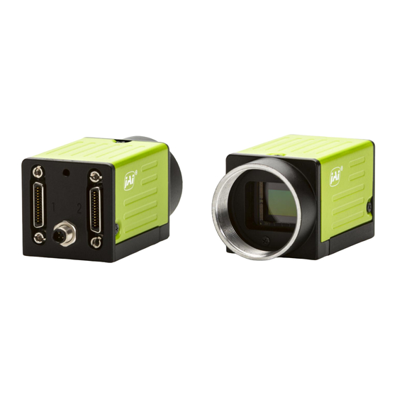
Page 8: Parts Identification
GO-5101M-PMCL / GO-5101C-PMCL Connection example: AC adapter External trigger Frame grabber board Camera Computer Parts Identification ② ③ ① ④ ⑤ 1 Lens mount (C-mount) Mount a C-mount lens, microscope adapter, etc. here. Before mounting a lens, be sure to refer to “Step 2: Connecting Devices” (page 13) and confirm the precautions for attaching a lens and the supported lens types. - Page 9 GO-5101M-PMCL / GO-5101C-PMCL 2 Mini Camera Link connector Connect a cable that is compatible with Mini Camera Link (SDR) connectors here. Camera side: HONDA HDR-EC26FYTG2-SL+ Port 1 Pin No. Input/output Signal Description 1, 26 Power Power 2(–), 15(+) X_OUT0 Data out 3(–), 16(+)
- Page 10 GO-5101M-PMCL / GO-5101C-PMCL 3 Power/trigger LED Indicates the power and trigger input status. LED status and camera status Light Status Power / trigger LED Camera initializing. Lit amber Operational and no triggers being input. Lit green Operational and triggers being input.
-
Page 11: Preparation
Note When the JAI SDK is installed, a camera driver for the interface is also part of the default installation. This Vision Filter Driver is added to every NIC/port on the host computer. As the driver is also added to the NIC/port for Internet connection, it may, on some systems, affect Internet access speed. - Page 12 GO-5101M-PMCL / GO-5101C-PMCL v Clear the [JAI Vision Filter Driver] checkbox, and save. Verify the settings for using Camera Link. The GO-5101-PMCL supports GenICam and Gen-CP. Check the following settings when controlling the camera via JAI SDK. Checking the frame grabber board's settings Settings must be configured on the frame grabber board to enable Gen-CP support.
-
Page 13: Step 2: Connecting Devices
GO-5101M-PMCL / GO-5101C-PMCL Step 2: Connecting Devices Connect the lens, Camera Link cable, AC adapter, and other devices. Attach the lens in a clean environment to prevent dust from adhering to the unit. 4 Frame grabber board 3 Camera Link cable... - Page 14 GO-5101M-PMCL / GO-5101C-PMCL To prevent vignetting and to obtain the optimal resolution, use a lens that will cover the 11 mm diagonal. Some lens manufacturers offer lenses with an 11 mm format. If not, a 2/3-inch lens is recommended. Caution •...
-
Page 15: Step 3: Verifying The Camera's Connection Status
GO-5101M-PMCL / GO-5101C-PMCL connector on the camera. The AC adapter is not required when using PoCL. Step 3: Verifying the Camera’s Connection Status When the necessary devices are connected and power is supplied to the camera, the power / trigger LED at the rear of the camera lights amber, and initialization of the camera starts. -
Page 16: Configuring The Output Format
GO-5101M-PMCL / GO-5101C-PMCL Configuring the Output Format Configure the size, position, and pixel format of the images to be acquired. The factory settings are as follows. Change the settings as necessary. Factory default values Item Default value Image Format Control... -
Page 17: Configuring Exposure And External Trigger Settings
GO-5101M-PMCL / GO-5101C-PMCL Example: When changing [Pixel Format] Note Direct entry of numerical and text values is possible for some setting items. Configuring Exposure and External Trigger Settings Configure settings related to exposure control methods and trigger control. The factory settings are as follows. Change settings as necessary, according to the intended purpose or application. -
Page 18: Control Via External Triggers
GO-5101M-PMCL / GO-5101C-PMCL Control via External Triggers When Controlling the Exposure Time Using Specified Exposure Times Configure the settings as follows. Item Setting value / selectable range Trigger Selector (trigger operation) Frame Start Trigger Mode Trigger Source (trigger signal source) -
Page 19: Control Without External Triggers
GO-5101M-PMCL / GO-5101C-PMCL Control Without External Triggers When Controlling the Exposure Time Using Specified Exposure Times Configure the settings as follows. Item Setting value / selectable range Trigger Selector (trigger operation) Frame Start Trigger Mode Exposure Mode Timed (control via exposure time) -
Page 20: Adjusting The Gain
Expand [Analog Control], and select the gain you want to configure in [Gain Selector]. • For the GO-5101M-PMCL, only [Analog All] (master gain) can be configured. • For the GO-5101C-PMCL, [Analog All] (master gain), [Digital Red] (digital R gain), and [Digital Blue] (digital B gain) can be configured individually. -
Page 21: Adjusting The Black Level
Expand [Analog Control], and select the black level you want to configure in [Black Level Selector]. For the GO-5101M-PMCL, only [Digital All] (master black) can be configured. For the GO-5101C-PMCL, [Digital All] (master black), [Digital Red] (digital R), and [Digital Blue] (digital B) can be configured individually. -
Page 22: To Save User Settings
GO-5101M-PMCL / GO-5101C-PMCL ■ To save user settings Stop image acquisition. Expand [User Set Control], and select the save destination ([User Set1] to [User Set3]) in [User Set Selector]. Note The factory default setting values are stored in [Default] and cannot be overwritten. -
Page 23: Basic Function Matrix
× − × × × 2 × 1 × − × × × 2 × 2 × − × × × *1 Operates only on the GO-5101M-PMCL *2 Operates only on the GO-5101C-PMCL — 23 —... -
Page 24: Main Functions
GO-5101M-PMCL / GO-5101C-PMCL Main Functions GPIO ( Digital Input/Output Settings) The unit can input/output the following signals to and from external input/output connectors. External output TTL Out (Line1) DC IN / trigger IN connector (4-pin round) External input TTL IN (Line4) -
Page 25: Valid Input/Output Combinations
GO-5101M-PMCL / GO-5101C-PMCL Valid Input/Output Combinations The following signals can be used as sources for each output destination (Trigger Selector, Line Selector, Pulse Generator Selector). You can also connect two different sources to NAND paths in the GPIO and reuse the signal generated there as a source for a different selector. -
Page 26: 1X2-1Y
GO-5101M-PMCL / GO-5101C-PMCL ■ 1X2-1Y 1X2-1Y is a 2-tap output format as defined in GenICam tap geometry. ■ 1X3-1Y 1X3-1Y is a 3-tap output format as defined in GenICam tap geometry. — 26 —... -
Page 27: 1X4-1Y
GO-5101M-PMCL / GO-5101C-PMCL ■ 1X4-1Y 1X4-1Y is a 4-tap output format as defined in GenICam tap geometry. ■ Cable length reference The following is a reference for the length of cable you can use based on the Camera Link clock*... -
Page 28: Maximum Frame Rate Period Formula
GO-5101M-PMCL / GO-5101C-PMCL ■ Maximum frame rate period formula During continuous operation ([Frame Start] trigger is [Off] or [Exposure Mode] is [Off]) • Maximum frame rate of sensor FR_Cont = 1 / {H Period × (Height + 34)} When the exposure time is longer than the frame interval •... -
Page 29: Exposure Mode
GO-5101M-PMCL / GO-5101C-PMCL Exposure Mode The following exposure modes are available on the camera. Exposure Mode Description Exposure control is not performed (free-running operation). Timed Mode in which control is performed using exposure time. Acquire images using an exposure time configured beforehand on an external trigger. -
Page 30: Horizontal Timing
GO-5101M-PMCL / GO-5101C-PMCL ■ Horizontal timing Line CL Pixel LineValid clock Total Line clock Total Line Period Line Rate (KHz) Tap Geometry BlankingClock Clock (MHz) (usec) [C] 1X2-1Y 37.125 1232 1236 33.293 30.036 (Full) 74.25 1232 1236 16.646 60.073 84.85... - Page 31 GO-5101M-PMCL / GO-5101C-PMCL CL Pixel Period from Period from Geometry Clock Trigger start Exposure Exposure Exposure (MHz) edge to end to [msec] [usec] Exposure FVAL start[A] start[B] (usec) (usec) 1X2-1Y 37.125 69.116 1X2-1Y 74.25 34.558 1X2-1Y 84.85 30.336 1X3-1Y 37.125 46.189...
-
Page 32: When [Exposure Mode] Is [Trigger Width]
GO-5101M-PMCL / GO-5101C-PMCL ■ When [Exposure Mode] is [Trigger Width] Example: When [Trigger Source] is set to [Line 7 - CC1] • Trigger overlap: Off Next trigger Next trigger disabled input enabled Trigger Sensor Exposure Readout duration (= Height x Line Period) -
Page 33: Gain Control
GO-5101M-PMCL / GO-5101C-PMCL Period from Period from Period from CL Pixel Trigger start Next trigger Trigger end Exposure Clock edge to start prohibited edge to Exposure Geometry end to FVAL (MHz) Exposure period[C](usec) Exposure [usec] start[B](usec) start[A](usec) end[D](usec) 1X2-1Y 37.125 1X2-1Y 74.25... -
Page 34: Lut (Lookup Table)
Red, Green, Blue LUT Index GO-5101M-PMCL: 0 to 256 Select the LUT index to configure. Indexes represent the GO-5101C-PMCL: 0 to 256 possible pixel values captured on the sensor, from the lowest value (Index 0) to the highest (Index 256). For example, Index 0 represents a full black pixel and Index 255 represents a full white pixel. -
Page 35: Gamma Function
GO-5101M-PMCL / GO-5101C-PMCL Gamma Function The gamma function corrects the output signals from the camera beforehand (reverse correction), taking into consideration the light-emitting properties of the monitor display. As the light-emitting properties of the monitor are not linear, the entire image may be darker or the gradation in the dark areas may be less noticeable when camera outputs are displayed without processing. -
Page 36: Automatic Detection
If a lens is attached, use the lens cap as a shield, for example. Configure the threshold level for defective pixel detection. Specify the threshold value for the blemishes to be detected using the [JAI Custom Control Blemish] - [Blemish Detect Threshold] setting. -
Page 37: Flat Shading
GO-5101M-PMCL / GO-5101C-PMCL 2560 (Total size) 2464 (Effective pixels) The following shading correction modes are available on the camera. ■ Flat Shading Correction is performed using the area of the screen with the highest brightness level as the reference, and adjusting the brightness levels of the other areas to match this level. -
Page 38: To Use The Shading Correction Function
GO-5101M-PMCL / GO-5101C-PMCL ■ To use the shading correction function Configure the settings as follows. Item Setting value Description Shading Correction Mode GO-5101M-PMCL: Select the shading correction mode. Flat Shading (fixed) GO-5101C-PMCL: Flat Shading, Color Shading Shading Mode User 1, User 2, User 3, Off Select the user area to which to save the shading correction value. -
Page 39: Sequencer Function
GO-5101M-PMCL / GO-5101C-PMCL Example 1: Without binning Example 2: With binning [Binning Horizontal] [Binning Horizontal] [Binning Vertical] [Binning Vertical] Scanning range Scanning range OffsetX Width OffsetX Width OffsetY OffsetY Height Height 1232 Width Max 2464 Width Max * GO-5101M-PMCL only ... - Page 40 GO-5101M-PMCL / GO-5101C-PMCL In Trigger Sequencer mode, patterns begin with the index of [Sequencer Set Start]. Subsequent triggers follow the user-defined values in [Sequencer Index Frame Count] and [Sequencer ROI Next Index]. Assigning a Next Index value of “1” to an index creates a loop back to the start of the sequencer pattern.
- Page 41 GO-5101M-PMCL / GO-5101C-PMCL Changing the value of [Command Sequencer Index] to one of the other predefined indexes causes that index to be executed in response to subsequent triggers. This mode of operation enables users to develop applications that continually send new values to [Command Sequencer Index] in response to external factors such as changing light conditions, different types or sizes of objects being inspected, or other factors.
-
Page 42: Alc (Automatic Level Control) Function
Set [Gain Auto] or [Exposure Auto] or both to [Continuous] mode. Configure the minimum value, maximum value, etc. for AGC and ASC under [JAI Custom Control ALC]. The target video levels for AGC and ASC are configured in [ALC Reference]. For example, when [ALC Reference] is set to 100%, video levels will be maintained at 100% for AGC and ASC. -
Page 43: Counter And Timer Control Function (Counter Support Only)
GO-5101M-PMCL / GO-5101C-PMCL Auto gain metering areas (16 areas) High High High High Mid-left Mid-right Right Left Mid-High Mid-High Mid-High Mid-High Left Mid-left Mid-right Right Mid-Low Mid-Low Mid-Low Mid-Low Mid-left Mid-right Right Left Mid-left Mid-right Right Left Counter and Timer Control Function (counter support only) The counter function counts up change points in the camera’s internal signals using the camera’s... -
Page 44: Internal Camera Blocks
GO-5101M-PMCL / GO-5101C-PMCL ■ Internal camera blocks Event Counter Frametrigger detection At event occurrence or count up Event Exposure Start Counter detection Event Frame Start Counter detection Event FrameTransfer End Counter detection Send information Counter reset Read requested to the HOST... -
Page 45: Video Process Bypass Mode
GO-5101M-PMCL / GO-5101C-PMCL Video Process Bypass Mode The video process bypass mode is a function that bypasses internal video processing on the camera. When bypass is enabled, the sensor output and camera output data can be set to the same bit width. -
Page 46: Settings List
GO-5101M-PMCL / GO-5101C-PMCL Settings List Feature Properties Item Setting range Default value Description a) Device Control Display/configure information related to the device. Device Vendor Name — “JAI Ltd., Japan” Display the manufacturer name. Device Model Name — GO-5101M- Display the model name. - Page 47 GO-5101M-PMCL / GO-5101C-PMCL Item Setting range Default value Description Pixel Format GO-5101M-PMCL: GO-5101M- Set the pixel format. Mono8, PMCL: [Mono12] and [BayerRG12] are enabled Mono10, Mono8 when [Video Process Bypass] is set to Mono12 GO-5101C- [On]. GO-5101C-PMCL: PMCL: BayerRG8, BayerRG8...
- Page 48 GO-5101M-PMCL / GO-5101C-PMCL Item Setting range Default value Description Black Level Selector GO-5101M-PMCL: Digital All Select the black level to configure. Digital All GO-5101C-PMCL: Digital All, Digital Red, Digital Blue Black Level –133 to 255 Set the black level value.
- Page 49 GO-5101M-PMCL / GO-5101C-PMCL Item Setting range Default value Description Sequencer Reset — — Reset the current index number to the number configured in [Sequencer Set Start]. g) Digital IO Control Configure settings for digital input/output. Line Selector Line1 - TTL Out, Line1 - TTL Out Select the input/output to configure.
- Page 50 GO-5101M-PMCL / GO-5101C-PMCL Item Setting range Default value Description Pulse Generator Length 1 to 1048575 30000 Set the maximum count-up value as a clock count. Pulse Generator Length 0.002222 to 2330.166666 66.6667 Set the maximum count-up value in (ms) milliseconds.
- Page 51 1 to 8 Select the AWB reaction speed. (for continuous) AWB Status — Idle Display the counter AWB. m) JAI Custom Control Blemish Configure settings for JAI white blemish correction. Blemish Enable True, False True Enable/disable blemish correction. Blemish Detect —...
- Page 52 Display the count value. Counter 0 to 2 Status Counter Active Counter Active Display the counter status. p) JAI Custom control Misc. Configure settings for other JAI functions. Video Process Bypass On, Off Enable / disable video process bypass Mode mode.
-
Page 53: Miscellaneous
GO-5101M-PMCL / GO-5101C-PMCL Miscellaneous Troubleshooting Check the following before requesting help. If the problem persists, contact your local JAI distributor. ■ Power supply and connections Problem Cause and solution The power / trigger LED remains lit amber and Camera initialization may not be complete. Check the Camera does not turn green, even after power is Link cable conection. -
Page 54: Specifications
GO-5101M-PMCL / GO-5101C-PMCL Specifications Item GO-5101M-PMCL GO-5101C-PMCL Scanning system Progressive scan, 1 tap Synchronization Internal Interface CameraLink (Version 2.0) Image sensor Monochrome CMOS Bayer color CMOS Image size (effective image) 8.5 (H) × 7.09 (V), 11.1 mm diagonal Pixel size 3.45 (H) ×... - Page 55 GO-5101M-PMCL / GO-5101C-PMCL Item GO-5101M-PMCL GO-5101C-PMCL Gain Manual adjustment range 0 dB to +24 dB 0 dB to +24 dB adjustment Auto gain Off, Continuous Off, Continuous WB gain — R / B: –7 dB to +15 dB, 1 step = 0.1 dB...
-
Page 56: Frame Rate Reference
GO-5101M-PMCL / GO-5101C-PMCL Frame Rate Reference (Theoretical value: decimal values are dropped, during Unpacked) Resolution Frame rate Pixel count ROI/Binning Pixel size(µm) Image size (screen size) 8 / 10 / 12 bit 5.1 MP 2464 × 2056 Full pixel 3.45 × 3.45 2/3"... -
Page 57: Dimensions
GO-5101M-PMCL / GO-5101C-PMCL GO-5101C-PMCL 1000 wave length (nm) Dimensions 41.5 C Mount 12.5 23.7 4-M2 Depth 3 3-M3 Depth 3 Dimensional tolerance: ±0.3 mm Unit: mm — 57 —... -
Page 58: User's Record
Revision: …………….. Serial No. …………….. Firmware version. …………….. For camera revision history, please contact your local JAI distributor. Trademarks • Microsoft and Windows are trademarks or registered trademarks of Microsoft Corporation in the United States and other countries. • Intel and Intel Core are trademarks of Intel Corporation in the United States and other countries. -
Page 59: Index
Video Process Bypass Mode 10, 45 Gain Auto 42 Gain Control 33 Gain Level 42 white balance 20 Gamma Function 35 GPIO 24 Initial Settings for the Camera 15 Installing the Software 11 JAI Camera Control Tool 11 JAI SDK 11 — 59 —... - Page 60 Revision history Revision Date Changes Mar. 2017 First draft May 2017 Power supply...
Need help?
Do you have a question about the GO-5101M-PMCL and is the answer not in the manual?
Questions and answers