Table of Contents
Advertisement
Quick Links
User Manual
GO-5100MP-PGE
5.1M CMOS Digital Progressive Scan
Polarized Camera
Document Version: 1.0
GO-5100MP-PGE_Ver.1.0_Jun.2019
Thank you for purchasing this product.
Be sure to read this manual before use.
This manual includes important safety precautions and instructions on how to operate the unit. Be sure to read
this manual to ensure proper operation.
The contents of this manual are subject to change without notice for the purpose of improvement.
© 2019 JAI
Advertisement
Table of Contents

Subscribe to Our Youtube Channel
Related Manuals for JAI GO-5100MP-PGE


Summary of Contents for JAI GO-5100MP-PGE
- Page 1 This manual includes important safety precautions and instructions on how to operate the unit. Be sure to read this manual to ensure proper operation. The contents of this manual are subject to change without notice for the purpose of improvement. © 2019 JAI...
-
Page 2: Table Of Contents
GO-5100MP-PGE Contents Gain Control ......... 38 Notice/Warranty/Certifications....3 Line Status ........... 38 Usage Precautions........5 Blemish Compensation......39 Features ..........6 Shading Correction ....... Parts Identifications....... 7 Sequencer Function....... Preparation ........... 11 Delayed Readout........44 Preparation Process......11 CounterAndTimerControl Function ..44 Step 1:Installing the Software(first time Chunk Data Function ...... -
Page 3: Notice/Warranty/Certifications
The material contained in this manual consists of information that is proprietary to JAI Ltd., Japan and may only be used by the purchasers of the product. JAI Ltd., Japan makes no warranty for the use of its product and assumes no responsibility for any errors which may appear or for damages resulting from the use of the information contained herein. - Page 4 GO-5100MP-PGE Supplement The following statement is related to the regulation on “ Measures for the Administration of the control of Pollution by Electronic Information Products “ , known as “ China RoHS “. The table shows contained Hazardous Substances in this camera.
-
Page 5: Usage Precautions
GO-5100MP-PGE Usage Precautions Notes on cable configurations The presence of lighting equipment and television receivers nearby may result in video noise. In such cases, change the cable configurations or placement. Notes on LAN cable connection Secure the locking screws on the connector manually, and do not use a driver. -
Page 6: Features
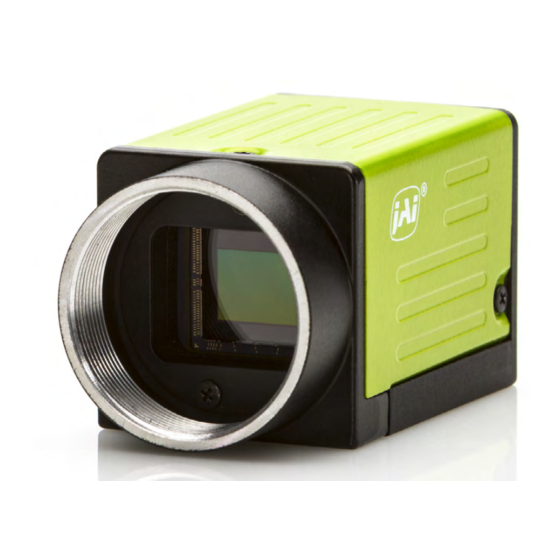
GO-5100MP-PGE Features The GO-5100MP-PGE is a machine vision polarization camera incorporating a monochrome CMOS image sensor with a 2/3-inch global shutter and a four-directional polarization square pixel array that offers 5.1 effective megapixels (2464 × 2056). The unit is compact and lightweight in design and is equipped with a GigE Vision Ver2.0 interface. -
Page 7: Parts Identifications
GO-5100MP-PGE Parts Identification ② ⑤ ④ ③ ① ⑥ ⑦ ① Lens mount(C-mount) Mount a C-mount lens, microscope adapter, etc. here. ❖ Before mounting a lens, be sure to refer to “Step 2:Connecting Devices” and confirm the precautions for attaching a lens and the supported lens types. - Page 8 GO-5100MP-PGE ③ POWER/TRIG LED Indicates the power and trigger input status. LED status and camera status Light Status POWER/ (Lit amber) Camera initializing. TRIG LED (Lit green) Camera in operation. (Blinking green) During operation in trigger mode, trigger signals are being input.
- Page 9 GO-5100MP-PGE Recommended external input circuit diagram (reference example) User Side JAI Camera User CAMERA side side Recommended external output circuit diagram (reference example) Standard circuit diagram example User Side JAI Camera CAMERA User side side — 9 —...
- Page 10 GO-5100MP-PGE Characteristics of the recommended circuits for Opto OUT ⑦ Camera locking screw holes(M3, 3 depth) Use these holes when attaching an MP-43 tripod adapter plate (optional) or mounting the camera directly to a wall or other structural system. * The smaller holes (x4) are M2 with a depth of 3mm.
-
Page 11: Preparation
When using the camera for the first time, install the software for configuring and controlling the camera (eBUS SDK for JAI) on the computer. ❖ When you install eBUS SDK for JAI, eBUS SDK for JAI player will also be installed. Download the eBUS SDK for JAI from the JAI website. -
Page 12: Step 2:Connecting Devices
GO-5100MP-PGE Step 2: Connecting Devices (or direct connection) Camera body ④ Network card ③ LAN Cable ① Lens ⑤ Computer ② Direct connection (or MP-45 tripod Switching hub adapter plate) ⑥ DC IN / trigger IN connection cable to external trigger ⑦... - Page 13 Install this in the computer that will be used to configure and operate the camera. As the GO-5100MP-PGE supports PoE, you can also use PoE-compatible network cards. Refer to the instruction manual of the network card, and configure settings on the computer as necessary.
-
Page 14: Step 3:Verifying Camera Operation
LED will remain green, even if the network is disconnected. Step 4: Verifying the Connection between the Camera and PC Verify whether the camera is properly recognized via eBUS Player for JAI. Connecting the Camera to eBUS Player for JAI. Startup eBUS Player for JAI eBUS Player for JAI startup screen appears. - Page 15 GO-5100MP-PGE Select the camera you want to configure. Push Select / Connect button The connected camera is listed. Please select one camera. — 15 —...
- Page 16 GO-5100MP-PGE Check that the settings of the selected camera are displayed. Push the Device control button. The screen shown below will be displayed. In this window you can adjust various settings of the camera. This completes the procedure for verifying whether the camera is properly recognized and whether control and settings configuration are possible.
-
Page 17: Step 5:Changing The Camera Settings
GO-5100MP-PGE Step 5: Changing the Camera Settings This section explains how to change settings by describing the procedure for changing the output format as an example. Configuring the Output Format Configure the size, position, and pixel format of the images to be acquired. -
Page 18: Step 6:Adjusting The Image Quality
GO-5100MP-PGE Step 6: Adjusting the Image Quality Display the camera image and adjust the image quality. Displaying the Image Display the image captured by the camera. When you push [Play] button, the camera image appears in right area. — 18 —... - Page 19 GO-5100MP-PGE Adjusting the Gain Adjust the image quality using the gain function. To adjust the image quality The Visibility must be changed from [Beginner] to [Guru]. Adjust the sensitivity via the analog gain (i.e., master gain). For details on gain control, see “Gain Control” in the “Main Functions” section.
-
Page 20: Step 7:Saving The Settings
GO-5100MP-PGE Step 7: Saving the Settings The setting values configured in the player (eBUS SDK for JAI) will be deleted when the camera is turned off. By saving current setting values to user memory, you can load and recall them whenever necessary. You can save up to three sets of user settings in the camera. - Page 21 GO-5100MP-PGE ■ To load user settings Stop image acquisition. User settings can only be loaded when image capture on the camera is stopped. Select the settings to load (UserSet1 to UserSet3) in [UserSetSelector]. Select [UserSetLoad], and click [Execute ‘UserSetLoad’ Command].
-
Page 22: Main Functions
GO-5100MP-PGE Main Functions Basic Function Matrix The combinations of settings for the basic functions that can be used together are as follows. Sequencer 1 x 1 × ○ ○ × × × × 1 x 2 × ○ × ×... -
Page 23: Camera Output Formats
Line Source Clear Source : Indicates default values for each selector. Camera Output Formats The GO-5100MP-PGE supports the following output formats. PixelFormat Mono8, Mono10, Mono10packed *1) Mono12, Mono12Packed *1) When VideoProcessBypassMode is enabled, PixelFormat can be set to Mono12 or Mono12Packed. -
Page 24: Camera Image Output Modes
GO-5100MP-PGE Camera Image Output Modes The GO-5100MP-PGE has two output modes(Raw Image mode, Polarize Angle And Degree mode). First, we will explain about the monochrome CMOS image sensor with a four-directional polarization square pixel array that is incorporated in this camera. - Page 25 GO-5100MP-PGE ■ Polarize Angle And Degree mode This mode calculates Polarize Angle and Polarize Degree in real time and outputs data. Polarize Angle : The polarization angle producing the greatest luminance for a given pixel block. (also referred to as AoLP: The Angle of Linear Polarization) Intensity values assigned to pixels represent angles from 0 to 180˚.
-
Page 26: Binning Function
GO-5100MP-PGE Binning Function The binning function allows you to combine the signal values of clusters of adjacent pixels to create improved virtual pixels. Using the function results in images with lower pixel resolution and higher sensitivity. This camera performs both horizontal binning and vertical binning via digital addition or averaging processing. - Page 27 GO-5100MP-PGE The image data output from this camera becomes RawImage with 2464 pixels (horizontally) x 1028 lines (vertically). 2464 pixels ■ When horizontal and vertical binning (2x2) The signal values of the pixels having polarizers at the same angle are combined.
-
Page 28: Roi(Regional Scanning Function)
GO-5100MP-PGE ROI (Regional Scanning Function) The ROI (region of interest) function allows you to output images by specifying the areas to scan. *) This function works Raw Image mode only. ROI Settings Specify the area to scan by specifying width, height, and horizontal/vertical offset values under [ImageFormatControl]. -
Page 29: Image Acquisition Controls
GO-5100MP-PGE Image Acquisition Controls Perform operations and configure settings related to image acquisition in [AcquisitionControl]. The following acquisition modes are available on the camera. AcquisitionMode Description SingleFrame Acquire a single frame when the [AcquisitionStart] command is executed. MultiFrame Acquire the number of frames specified in [AcquisitionFrameCount] when the [AcquisitionStart] command is executed. - Page 30 GO-5100MP-PGE ■ About H_Period, Pack value H_Period and Pack value are the below. PixelFormat H_period (us) Mono8 13.414 Mono10 Packed, Mono12 Packed 26.343 Mono10, Mono12 26.343 PixelFormat Pack Value Mono8 Mono10 Packed, Mono12 Packed Mono10, Mono12 ■ During continuous operation ([Frame Start] trigger is [Off] or [Exposure Mode] is [Off]) •...
-
Page 31: Exposuremode
GO-5100MP-PGE ■ When [Frame Start] trigger is [On] and [Trigger OverLap] is [Readout] • Maximum frame rate of sensor Sensor FR = 1 / {H_Period × (Height + 36)} • Maximum frame rate by interface Interface FR = 920 × 1000000 / (Height × Width × Pack value) •... -
Page 32: Trigger Control
GO-5100MP-PGE Trigger Control The camera allows the following controls to be performed via external trigger signals. TriggerSelector Description FrameStart Start exposure in response to the external trigger signal input. Select this to perform exposure control using external triggers. AcquisitionStart Start image acquisition in response to the external trigger signal input. - Page 33 GO-5100MP-PGE ■ When [ExposureMode] is [Timed] Example: When [TriggerSource] is set to [Line 5 - OptIn1] and [OptInFilterSelector] is set to [10 µs] • TriggerOverlap:Off Next trigger Input enabled* Next trigger disabled Trigger Sensor Exposure ExposureActive Exposure time Readout (minimum) 40 μs...
- Page 34 GO-5100MP-PGE • TriggerOverlap:readout Next trigger Input enabled* Next trigger disabled Trigger Sensor Exposure ExposureActive Exposure time Readout minimum 40 μs 173 μs 8 bit 10 μs 10 bit packed (minimum) 79 μs 328 μs 10 bit *) If the exposure time is longer than (input trigger cycle - t3), the next trigger input will not be accepted.
- Page 35 GO-5100MP-PGE ■ When [ExposureMode] is [TriggerWidth] Example: When [TriggerSource] is set to [Line 5 - Optical In 1] and [OptInFilterSelector] is set to [10 µs] • TriggerOverlap:Off Next trigger Next trigger disabled Input enabled* Trigger Sensor Exposure ExposureActive Readout minimum 40 μs...
- Page 36 GO-5100MP-PGE • TriggerOverlap:readout Next trigger Next trigger disabled Input enabled* Trigger Sensor Exposure ExposureActive Readout minimum 40 μs 40 μs 173 μs 8 bit 10 μs ( 10 bit packed minimum 79 μs 79 μs 328 μs 10 bit *) If the exposure time is longer than (input trigger cycle – t4), the next trigger input will not be accepted.
-
Page 37: Gain Control
GO-5100MP-PGE Gain Control Adjust the [AnalogAll] (master gain) setting. Analog All x 16 24dB x 1.0 LineStatus The line status function allows you to verify the status of external input/output signals. You can verify the status of the following signals. -
Page 38: Blemish Compensation
GO-5100MP-PGE Blemish Compensation Multiple defective pixels that are not adjacent to each other can occur on conventional CMOS sensor cameras. This camera features a function that interpolates defective pixels using the surrounding pixels. Up to 256 pixels can be corrected for each of the three sensors. Pixel interpolation can be performed via automatic detection or point-by-point manual settings. -
Page 39: Shading Correction
GO-5100MP-PGE Shading Correction The shading correction is a function that corrects non-uniformity (i.e., shading) in the amount of light generated by the lens and lighting equipment. Using this function allows correction even if top, bottom, left, and right shading is not symmetrical in relation to the center of the screen (H, V). - Page 40 GO-5100MP-PGE ■ To use the shading correction function Configure the settings as follows. Item Setting value Description ShadingCorrectionMode FlatShading Select the shading correction mode. ShadingMode User1, User2, User3, Off Select the user area to which to save the shading correction value.
-
Page 41: Delayed Readout
GO-5100MP-PGE Delayed Readout Delayed readout allows images captured by a [FrameStart] trigger command to be stored temporarily inside the camera (delayed readout buffer) and read out using a [AcquisitionTransferStart] trigger after capture.This function is useful when executing triggers simultaneously on multiple cameras. -
Page 42: Counterandtimercontrol Function
GO-5100MP-PGE CounterAndTimerControl Function The counter function counts up change points in the camera’s internal signals using the camera’s internal counter, and reads that information from the host side. This function is useful for verifying error conditions via the count value using internal camera operations.Counting is performed at frame trigger, frame start, exposure start, and exposure... -
Page 43: Videoprocessbypassmode
GO-5100MP-PGE ■ Internal camera blocks ■ To use the counter function Configure the settings as follows. Three counters can be configured (Counter 0 to 2). Setting value / Item selectable range Description Counter 0 to 2 Counter 0 to 2 Select the counter. - Page 44 Events that can use the Event Control Function are as follows. You can specify whether or not to send an event message when an event occurs at each event. AcquisitionTrigger, FrameStart, FrameEnd, Jai FVAL Start, Jai FVAL End, Exposure Start, Exposure End, OptOut1RisingEdge,...
- Page 45 GO-5100MP-PGE Action Control Function The Action Control Function is a function that executes the pre-configured action when the camera receives action commands. Action commands can send both unicast and broadcast messages and give instructions for actions to multiple cameras simultaneously by broadcasting them.
-
Page 46: Setting List
GO-5100MP-PGE Settings List Feature Properties Item Setting range Default value Description a) Device Control Display/configure information related to the device. Device Vendor Name ー "JAI Corporation" Display the manufacturer name. Device Model Name ー GO-5100MP-PGE Display the model name. Device Manufacturer Info ー... - Page 47 Configure event control settings. Event Selector ー AcquisitionTrigger Select the event for which to send notifications. [Setting range] AcquisitionTrigger, FrameStart, FrameEnd, Jai FVAL Start, Jai FVAL End, Exposure Start, Exposure End, OptOut1RisingEdge, Line2RisingEdge, OptOut2RisingEdge, Line3RisingEdge, OptIn1RisingEdge, Line5RisingEdge, OptOut1FallingEdge, Line2FallingEdge, OptOut2FallingEdge, Line3FallingEdge, OptIn1FallingEdge, Line5FallingEdge,...
- Page 48 GO-5100MP-PGE Item Setting range Default value Description e) Analog Control Configure analog control settings. Gain Selector Analog All Analog All Select the gain to configure. Gain x1.0 to x16.0 x1.0 Set the gain value for the gain setting selected in [GainSelector].
- Page 49 GO-5100MP-PGE Item Setting range Default value Description g) PulseGenerator Configure pulse generator settings. Clock Pre Scaler 1 to 4096 Set the division value for the prescaler (12 bit) using PixelClock as the base clock. Pulse Generator Clock (MHz) 0.0181274 to 74.25 0.45...
- Page 50 GO-5100MP-PGE Item Setting range Default value Description h) TransportLayerControl Display information on transport layer control. PlayloadSize 5065984 Display the payload size. GevVersionMajor ー Display the GigE version. GevVersionMinor ー GevDeviceModeIsBigEndian ー True Display the endianness. GevDeviceModeCharacterSet ー UTF8 Display the charater set.
- Page 51 GO-5100MP-PGE GevSCPHostPort ー 55351 Set the port number for the stream channel. GevSCPSDoNotFragment True, False True Enable/disable "Do Not Fragment". GevSCPSPacketSize 1476 to 16020 1476 Set the packet size. GevSCPD 0 to 4000000 Set the packet delay. GevSCDA ー ー...
- Page 52 GO-5100MP-PGE Item Setting range Default value Description k)JAICustomControlALC Configure JAI ALC settings. These settings are also used for AGC (auto gain control). ALCReference 10 to 95 Set the target level for ALC. (unit: %) ー Low Right Select the area for which to configure [ALC Area ALCAreaSelector Enable].
- Page 53 Raw Image Set the video output mode Polarize Angle And Degree Item Setting range Default value Description p) JAICustomControlMisc Configure settings for other JAI functions. VideoProcessBypassMode Off, On Enable/disable VideoProcessBypass mode. Trigger Option OptIn Filter Selector 10μs, 100μs, 500μs, 10μs...
-
Page 54: Miscellaneous
GO-5100MP-PGE Miscellaneous Troubleshooting Check the following before requesting help. If the problem persists, contact your local JAI distributor. ■ Power supply and connections Problem Cause and solution The POWER/TRIG LED remains lit amber and Camera initialization may not be complete does not turn green, even after power is due to lack of a network connection. -
Page 55: Specifications
GO-5100MP-PGE Specifications Item GO-5100MP-PGE Scanning system Progressive scan, 1 tap Synchronization internal Interface 1000BASE-T Ethernet (GigE Vision 2.0 compatible), IEEE 802.3af Image sensor monochrome CMOS image sensor with a four-directional polarization grid Image size (effective image) 2/3-inch 8.5mm(H) x 7.09mm(V) : 11.1mm(diagonal) Pixel size 3.45 μm (H) x 3.45μm(V) - Page 56 GO-5100MP-PGE Package contentsCamera body (1) Sensor protection cap (1) Dear Customer (sheet) (1) Optional accessories (not supplied) MP-43 tripod mount Design and specifications are subject to change without notice. Approximately 30 minutes of warm-up are required to achieve these specifications.
-
Page 57: Frame Rate Reference
GO-5100MP-PGE Frame Rate Reference [Theoretical value] Pixel count Resolution Pixel size Imge size Frame rate (MP) (screen size) (um) (mm) (fps @8bit) 5.1MP 2464 x 2056 3.45 x 3.45 2/3" (11.1 mm) 22.7 1920 x 1080 3.45 x 3.45 1/2"... -
Page 58: Dimensions
GO-5100MP-PGE Dimensions Depth3 Depth3 Dimenstional tolerance: ± 0.3mm Unit: mm — 58 —... -
Page 59: Comparison Of The Decibel Display And Multiplier Display
GO-5100MP-PGE Comparison of the Decibel Display and Multiplier Display Decibels[db] Multipliers[x] Remarks 0.501 0.562 0.631 0.708 0.794 0.891 1.122 1.259 1.413 1.585 1.778 1.995 2.239 2.512 2.818 3.162 3.548 3.981 4.467 5.012 5.623 6.31 7.079 7.943 8.913 11.22 12.589 14.125 15.849... -
Page 60: User's Record
Camera type: GO-5100MP-PGE Revision: …………… Serial No: …………… Firmware version: …………… For camera revision history, please contact your local JAI distributor. Trademarks • Microsoft and Windows are trademarks or registered trademarks of Microsoft Corporation in the United States and other countries. -
Page 61: Index
GO-5100MP-PGE Index 6-pin round 8 LED 7 Lens 12 Lens mount 7 Acquisition Control 30 Line Status 38 Acquisition modes 30 Adjusting the Black Level 19 Adjusting the Gain 19 Maximum Frame Rate 30 Binning Function 27 Optional accessories (not supplied) 61... - Page 62 GO-5100MP-PGE Revision history Revision Date Changes First version Jun. 2019 — 62 —...
Need help?
Do you have a question about the GO-5100MP-PGE and is the answer not in the manual?
Questions and answers