Table of Contents
Advertisement
Thank you for purchasing this product.
Be sure to read this manual before use.
This manual includes important safety precautions and instructions on how to operate the unit. Be sure to read
this manual to ensure proper operation.
The contents of this manual are subject to change without notice for the purpose of improvement.
© 2021 JAI
User Manual
GOX-2402M-PGE / GOX-2402C-PGE
GOX-3201M-PGE / GOX-3201C-PGE
GOX-5103M-PGE / GOX-5103C-PGE
GOX-8901M-PGE / GOX-8901C-PGE
GOX-12401M-PGE / GOX-12401C-PGE
CMOS Digital Progressive Scan
Monochrome and color Camera
Document Version: 1.0
GO-X_Series_PGE_Ver.1.0 _Mar.2021
Advertisement
Table of Contents

Related Manuals for JAI GOX-2402M-PGE


Summary of Contents for JAI GOX-2402M-PGE
- Page 1 User Manual GOX-2402M-PGE / GOX-2402C-PGE GOX-3201M-PGE / GOX-3201C-PGE GOX-5103M-PGE / GOX-5103C-PGE GOX-8901M-PGE / GOX-8901C-PGE GOX-12401M-PGE / GOX-12401C-PGE CMOS Digital Progressive Scan Monochrome and color Camera Document Version: 1.0 GO-X_Series_PGE_Ver.1.0 _Mar.2021 Thank you for purchasing this product. Be sure to read this manual before use.
-
Page 2: Table Of Contents
Go-X Series GigE Vision I/F Contents Notice/Warranty/Certifications Blemish Compensation Usage Precautions Shading Correction Features Binning Function Parts Identifications Decimation mode ROI Function (Single ROI) Preparation Pulse Generator Preparation Process Sequencer Function Step 1: Installing the Software Counter And Timer Control Function Step 2: Connecting Devices Chunk Data Function Step 3: Verifying Camera Operation... -
Page 3: Notice/Warranty/Certifications
The material contained in this manual consists of information that is proprietary to JAI Ltd., Japan and may only be used by the purchasers of the product. JAI Ltd., Japan makes no warranty for the use of its product and assumes no responsibility for any errors which may appear or for damages resulting from the use of the information contained herein. - Page 4 Go-X Series GigE Vision I/F Supplement The following statement is related to the regulation on “Measures for the Administration of the control of Pollution by Electronic Information Products“ , known as “China RoHS“. The table shows contained Hazardous Substances in this camera. mark shows that the environment-friendly use period of contained Hazardous Substances is 15 years.
- Page 5 Go-X Series GigE Vision I/F Supplement The following statement is related to the regulation on “Measures for the Administration of the control of Pollution by Electronic Information Products“ , known as “China RoHS“. The table shows contained Hazardous Substances in this camera. mark shows that the environment-friendly use period of contained Hazardous Substances is 15 years.
-
Page 6: Usage Precautions
Go-X Series GigE Vision I/F Usage Precautions Notes on cable configurations The presence of lighting equipment and television receivers nearby may result in video noise. In such cases, change the cable configurations or placement. Notes on LAN cable connection Secure the locking screws on the connector manually, and do not use a driver. -
Page 7: Features
Color models : BayerRG8, BayerRG10, BayerRG10Packed, BayerRG12, BayerRG12Packed • Gamma correction circuit that uses lookup tables • Internal test signal for settings configuration • Compatible with free eBUS SDK for JAI Connection example: PoE-compatible switching hub Camera AC adapter External Trigger... -
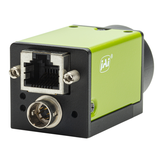
Page 8: Parts Identifications
Go-X Series GigE Vision I/F Parts Identification ② ④ ⑤ ③ ① ⑥ ⑦ ⑧ ⑨ ① Lens mount(C-mount) Mount a C-mount lens, microscope adapter, etc. here. ❖ Before mounting a lens, be sure to refer to “Step 2:Connecting Devices” and confirm the precautions for attaching a lens and the supported lens types. - Page 9 Go-X Series GigE Vision I/F ③ POWER/TRIG LED Indicates the power and trigger input status. LED status and camera status Light Status POWER/ (Lit amber) Camera initializing. TRIG LED (Lit green) Camera in operation. (Blinking green) During operation in trigger mode, trigger signals are being input.
- Page 10 Go-X Series GigE Vision I/F ■ Recommended external input circuit diagram (reference example) Opto In + (Pin2) Opto In - (Pin3) ■ Recommended external output circuit diagram (reference example) Opto Out + (Pin4) Opto Out - (Pin5) OPTO-In circuit characteristics Technical notes —...
- Page 11 Go-X Series GigE Vision I/F Characteristics of the recommended circuits for Opto OUT OUTPUT LINE RESPONSE TIME Camera Output Signal Output Line Voltage For the operating conditions of applied voltage (User Power) +12V, load resistance 10kΩ, and cable length 1m, the timing is shown in the table below. Item Result (Typ) (μs)
-
Page 12: Preparation
When using the camera for the first time, install the software for configuring and controlling the camera (eBUS SDK for JAI) on the computer. ❖ When you install eBUS SDK for JAI, eBUS SDK for JAI player will also be installed. Download the eBUS SDK for JAI from the JAI website. -
Page 13: Step 2: Connecting Devices
9 mm or less Lens mount protrusion Lens ・To prevent vignetting and to obtain the optimal resolution, use a lens that will cover the image sensor size. Model name Image Sensor GOX-2402M-PGE Mono 1/2.3 inch 6.62mm x 4.14mm (7.81mm diagonal) GOX-2402C-PGE Color GOX-3201M-PGE Mono 1/1.8 inch... - Page 14 Go-X Series GigE Vision I/F Note The following formula can be used to estimate the focal length. Focal length = WD /(1 + W/w) WD :Working distance (distance between lens and object) :Width of object :Width of sensor ② Direct connection(or MP-43 tripod adapter plate) When mounting the camera directly to a wall or other device, use screws that match the camera locking screw holes on the camera (M3, depth: 3 mm).
-
Page 15: Step 3: Verifying Camera Operation
Verifying the Connection between the Camera and PC Verify whether the camera is properly recognized via Control Tool. Connecting the Camera to Control Tool Startup eBUS Player for JAI eBUS Player for JAI eBUS Player for JAI startup screen appears. — 15 —... - Page 16 Go-X Series GigE Vision I/F eBUS Player for JAI File Tools Help Connection Disconnect Select / Connect IP address MAC address GUID Vendor Model Name Acquisition Control Source Mode Play Stop Parameters and Controls Communication control Device control Image stream control Select the camera you want to configure.
- Page 17 Go-X Series GigE Vision I/F Check that the settings of the selected camera are displayed. eBUS Player for JAI File Tools Help Connection Disconnect Select / Connect IP address MAC address GUID XXXXXXXXXXX Vendor JAI Corporation GOX-3201C-PGE Model JAI_DEMO Name...
-
Page 18: Step 5: Changing The Camera Settings
* You can specify the image acquisition area. For details, see “ROI (Regional Scanning Function)”. Configuring the [Width] of[ImageFormatControl] By selecting the item of [Width], you can change the value as shown below. × Device Control Visibility Beginner DeviceControl DeviceVendorName JAI Corporation DeviceModelName GOX-3201C-PGE DeviceManufactureInfo See the possibilities DeviceVersion XXXXX DeviceFirmwareVersion XXXXX... -
Page 19: Step 6: Adjusting The Image Quality
Display the camera image and adjust the image quality. Displaying the Image Display the image captured by the camera. When you push [Play] button, the camera image appears in right area. eBUS Player for JAI File Tools Help Connection Disconnect... - Page 20 Go-X Series GigE Vision I/F Adjusting the Gain Adjust the image quality using the gain and white balance* functions. *) Color model only To adjust the image quality The Visibility must be changed from [Beginner] to [Guru]. Adjust the sensitivity via the analog gain (i.e., master gain). For details on gain control, see “Gain Control”...
-
Page 21: Step 7: Saving The Settings
*) Color model only Step 7: Saving the Settings The setting values configured in the player (eBUS SDK for JAI) will be deleted when the camera is turned off. By saving current setting values to user memory, you can load and recall them whenever necessary. - Page 22 Go-X Series GigE Vision I/F Select [UserSetSave], and click [Execute ‘UserSetSave’ Command]. The current setting values are saved as user settings. ■ To load user settings Stop image acquisition. User settings can only be loaded when image capture on the camera is stopped. Select the settings to load (UserSet1 to UserSet3) in [UserSetSelector].
-
Page 23: Main Functions
Go-X Series GigE Vision I/F Main Functions Acquisition Control This camera has three Acquisition modes (SingleFrame, MultFrame, Continuous). Use [AcquisitionControl] settings to perform operations and settings for image capture. SingleFrame When the [AcquisitionStart] command is executed, one frame of image is captured. Acquisition Acquisition Start... -
Page 24: Exposure Mode
13.7 μs, use 14.7 μs - 13.7 μs = 1 μs as the high or low time for the trigger signal. Model name Image sensor's offset GOX-2402M-PGE The offset time varies depending GOX-2402C-PGE on the model as shown in the table GOX-3201M-PGE on the left. - Page 25 Go-X Series GigE Vision I/F RCT mode RCT mode can be used when [Exposure Mode] is Timed and [Frame Start Trigger] is enabled. In RCT mode, the image is not output from the camera until FrameStartTrigger is input, but internally the imaging operation is continued and the automatic gain control (AGC) function and the automatic shutter control (ASC) function can be continued.
-
Page 26: Trigger Control
Go-X Series GigE Vision I/F Trigger Control The camera allows the following controls to be performed via external trigger signals. TriggerSelector Description AcquisitionStart Start image acquisition in response to the external trigger signal input. AcquisitionEnd Stop image acquisition in response to the external trigger signal input. FrameStart Start exposure in response to the external trigger signal input. -
Page 27: Pixel Format
Go-X Series GigE Vision I/F Pixel Format Selectable PixelFormat is as follows. Color model : BayerRG8, BayerRG10, BayerRG10Packed, BayerRG12, BayerRG12Packed Monochrome model : Mono8, Mono10, Mono10Packed, Mono12, Mono12Packed Note In color model, the Bayer array is changed by the image flip function. ReverseX : 0 (False) ReverseY : 0 (False) ->... -
Page 28: Gpio (Digital Input/Output Settings)
Go-X Series GigE Vision I/F GPIO (Digital Input/Output Settings) The unit can input/output the following signals to and from external input/output connectors. External output Line2 : Opt Out DC IN / TRIG IN connector (6-pin round) External input Line5 : Opt In DC IN / TRIG IN connector (6-pin round) These signals can be used as triggers and other necessary signals within the camera or as signals output from the camera to the system, such as those used for lighting... -
Page 29: Videoprocessbypassmode
Go-X Series GigE Vision I/F VideoProcessBypassMode The video process bypass mode is a function that bypasses internal video processing on the camera. When bypass is enabled, the sensor output and camera output data can be set to the same bit depth. 12-bit outputs can only be performed in bypass mode. -
Page 30: Calculate The Maximum Frame Rate
(Number of pixels and number of lines before Binning). *) In GOX-2402M-PGE, 2x2 binning is processed on the image sensor. Therefore, the maximum sensor frame rate can be increased. In this case, for the values of Width-S and Height-S, specify the number of pixels and the number of lines after Binning. - Page 31 Go-X Series GigE Vision I/F ■ During Continuous operation ([Frame Start] trigger is [Off]) FR_Cont[Hz] = MIN(Interface_FR, Sensor_FR) ■ When [TriggerMode] is [On] ([Frame Start] trigger is [On]) First, calculate the maximum OverlapTime value for the shortest trigger cycle. MaxOverlapTime_TrOlrd[us] = (1000000/FR_Cont) - (14 x H_period) ・When ExposureTime ≦...
-
Page 32: Timing Chart (Gox-2402Mc-Pge)
Go-X Series GigE Vision I/F Timing chart (GOX-2402MC-PGE) ■ When [ExposureMode] is [Timed] • FrameStartTrigger On A (Frame Period) Next trigger Input enabled Next trigger disabled Trigger Sensor Exposure Exposure Exposure time Active Readout Period From Trigger start edge to PixelFormat Frame Period [A] (usec) Exposure start [B] (usec) - Page 33 Go-X Series GigE Vision I/F ■ When [ExposureMode] is [TriggerWidth] • FrameStartTrigger On A (Frame Period) Next trigger Input enabled (Next trigger disabled) Trigger Sensor Exposure Exposure ExposureTime Active Readout Period From Trigger start edge Period From Trigger end to Period From Exposure end to next PixelFormat Frame Period [A] (usec)
-
Page 34: Timing Chart (Gox-3201Mc-Pge)
Go-X Series GigE Vision I/F Timing chart (GOX-3201MC-PGE) ■ When [ExposureMode] is [Timed] • FrameStartTrigger On A (Frame Period) Next trigger Input enabled Next trigger disabled Trigger Sensor Exposure Exposure Exposure time Active Readout Period From Trigger start edge to PixelFormat Frame Period [A] (usec) Exposure start [B] (usec) - Page 35 Go-X Series GigE Vision I/F ■ When [ExposureMode] is [TriggerWidth] • FrameStartTrigger On A (Frame Period) Next trigger Input enabled (Next trigger disabled) Trigger Sensor Exposure Exposure ExposureTime Active Readout Period From Trigger start edge Period From Trigger end to Period From Exposure end to next PixelFormat Frame Period [A] (usec)
-
Page 36: Timing Chart (Gox-5103Mc-Pge)
Go-X Series GigE Vision I/F Timing chart (GOX-5103MC-PGE) ■ When [ExposureMode] is [Timed] • FrameStartTrigger On A (Frame Period) Next trigger Input enabled Next trigger disabled Trigger Sensor Exposure Exposure Exposure time Active Readout Period From Trigger start edge to PixelFormat Frame Period [A] (usec) Exposure start [B] (usec) - Page 37 Go-X Series GigE Vision I/F ■ When [ExposureMode] is [TriggerWidth] • FrameStartTrigger On A (Frame Period) Next trigger Input enabled (Next trigger disabled) Trigger Sensor Exposure Exposure ExposureTime Active Readout Period From Trigger start edge Period From Trigger end to Period From Exposure end to next PixelFormat Frame Period [A] (usec)
-
Page 38: Timing Chart (Gox-8901Mc-Pge)
Go-X Series GigE Vision I/F Timing chart (GOX-8901MC-PGE) ■ When [ExposureMode] is [Timed] • FrameStartTrigger On A (Frame Period) Next trigger Input enabled Next trigger disabled Trigger Sensor Exposure Exposure Exposure time Active Readout Period From Trigger start edge to PixelFormat Frame Period [A] (usec) Exposure start [B] (usec) - Page 39 Go-X Series GigE Vision I/F ■ When [ExposureMode] is [TriggerWidth] • FrameStartTrigger On A (Frame Period) Next trigger Input enabled (Next trigger disabled) Trigger Sensor Exposure Exposure ExposureTime Active Readout Period From Trigger start edge Period From Trigger end to Period From Exposure end to next PixelFormat Frame Period [A] (usec)
-
Page 40: Timing Chart (Gox-12401Mc-Pge)
Go-X Series GigE Vision I/F Timing chart (GOX-12401MC-PGE) ■ When [ExposureMode] is [Timed] • FrameStartTrigger On A (Frame Period) Next trigger Input enabled Next trigger disabled Trigger Sensor Exposure Exposure Exposure time Active Readout Period From Trigger start edge to PixelFormat Frame Period [A] (usec) Exposure start [B] (usec) - Page 41 Go-X Series GigE Vision I/F ■ When [ExposureMode] is [TriggerWidth] • FrameStartTrigger On A (Frame Period) Next trigger Input enabled (Next trigger disabled) Trigger Sensor Exposure Exposure ExposureTime Active Readout Period From Trigger start edge Period From Trigger end to Period From Exposure end to next PixelFormat Frame Period [A] (usec)
-
Page 42: Gain Control
Go-X Series GigE Vision I/F Gain Control Adjust the [AnalogAll] (master gain) setting first, and then adjust the [AnalogRed], [DigitalRed]. Color model Digital Red Digital Blue Analog All 15dB 15dB x 16 24dB -7dB -7dB 15dB 15dB x 1.0 -7dB -7dB Monochrome model Digital All... -
Page 43: White Balance
Go-X Series GigE Vision I/F White Balance To adjust the white balance automatically, set [BalanceWhiteAuto] to Once (automatic adjustment only once) or Continuous (automatic adjustment always). The metering area can be limited for automatic adjustment. To limit the metering area, specify each of the 16 areas with [AWBAreaSelector] and set [AWBAreaEnable] to True or False. -
Page 44: Alc (Automatic Level Control) Function
Go-X Series GigE Vision I/F ALC (Automatic Level Control) Function The ALC (automatic level control) function combines the automatic gain control (AGC/Auto Gain Control) and automatic exposure control (ASC/Auto Shutter Control) functions, and is capable of handling various changes in brightness.The function operates as follows in response to changes in brightness. -
Page 45: Gamma Function
Go-X Series GigE Vision I/F Gamma Function The gamma function corrects the output signals from the camera beforehand (reverse correction), taking into consideration the light-emitting properties of the monitor display. As the light-emitting properties of the monitor are not linear, the entire image may be darker or the gradation in the dark areas may be less noticeable when camera outputs are displayed without processing. -
Page 46: Lut (Lookup Table)
Go-X Series GigE Vision I/F LUT (Lookup Table) The LUT function is used to generate a non-linear mapping between signal values captured on the sensor and those that are output from the camera. You can specify the output curve using 257 setting points (indexes). ■... -
Page 47: Blemishcompensation
Go-X Series GigE Vision I/F BlemishCompensation Multiple defective pixels that are not adjacent to each other can occur on conventional CMOS sensor cameras. This camera features a function that interpolates defective pixels using the surrounding pixels. Up to 256 pixels can be corrected. Pixel interpolation can be performed via automatic detection or point-by-point manual settings. -
Page 48: Shading Correction
Go-X Series GigE Vision I/F Shading Correction The ShadingCorrection function corrects non-uniformity (i.e., shading) in the amount of light generated by the lens and lighting equipment. Using this function allows correction even if top, bottom, left, and right shading is not symmetrical in relation to the center of the screen (H, V). -
Page 49: Binning Function
GOX-12401M-PGE averaging processing averaging processing * In GOX-2402M-PGE, 2x2 binning is processed in the image sensor. Note ・If Binning function is active, [BlemishDetect] does not work. Decimation mode Decimation mode performs 2X downsampling of the image horizontally, vertically, or both. -
Page 50: Roi Function (Single Roi)
Height (lines) H Binning Off : 96 to 1920 step 16 V Binning Off : 8 to 1200 step 2 GOX-2402M-PGE H Binning On : 48 to 960 step 8 V Binning On : 4 to 600 step 1 H Binning Off : 96 to 2048 step 16... - Page 51 Go-X Series GigE Vision I/F Color model Model name Width (pixels) Height (lines) GOX-2402C-PGE 96 to 1920 step 16 8 to 1200 step 2 GOX-3201C-PGE 96 to 2048 step 16 8 to 1536 step 2 96 to 2448 step 16 8 to 2048 step 2 GOX-5103C-PGE 96 to 4096 step 16...
-
Page 52: Pulse Generator
Go-X Series GigE Vision I/F Pulse Generator By using this function, any signal can be generated inside the camera. The following is an example of signal generation. Settings PulseGeneratorStartPoint = 2 PulseGeneratorEndPoint = 6 PulseGeneratorLength = 10 PulseGeneratorPulseWidth = 4 PulseGeneratorClearSyncMode = AsyncMode StartPoint EndPoint... -
Page 53: Sequencer Function
Go-X Series GigE Vision I/F Sequencer Function The Sequencer function lets you define up to 32 index combinations of exposure time, gain, ROI, and other settings which can be stepped through each time a trigger is received.This is particularly useful for quickly capturing multiple exposures of objects under inspection to adjust for areas or components with significantly different levels of reflectance. - Page 54 Go-X Series GigE Vision I/F Sample TriggerSequencer mode operation User-defined Indexes (up to 32) Triggers/ Image Frames Specify "1" in [SequencerSetStart], and start TriggerSequencer mode with index 1. Capture a 2-frame image with the first and second triggers. For the next index, configure index 3 specified in [SequencerSetNext], and capture an image with the number of frames (number of triggers) specified in [SequencerFrameNumber].
-
Page 55: Counter And Timer Control Function
Go-X Series GigE Vision I/F Counter And Timer Control Function This camera supports only the counter function. The counter function counts up change points in the camera’s internal signals using the camera’s internal counter, and reads that information from the host side. This function is useful for verifying error conditions via the count value using internal camera operations. - Page 56 Go-X Series GigE Vision I/F ■ Internal camera blocks Counter0 Counter Event detection FrameStartTrigger At event occurrence or count up Counter1 Counter Event detection ExposureStart At event occurrence or count up Counter2 Counter Event detection SensorReadOut At event occurrence or count up Counter3 Counter Event detection...
-
Page 57: Chunk Data Function
Go-X Series GigE Vision I/F Chunk Data Function The Chunk Data function adds camera configuration information to the image data that is output from the camera. Embedding camera configuration information in the image data allows you to use the serial number of the camera as a search key and find specific image data from among large volumes of image data. -
Page 58: Event Control Function
Go-X Series GigE Vision I/F Event Control Function The Event Control Function is a function that outputs a signal change point inside the camera as information indicative of an event occurrence (event message) by using GVCP (GigE Vision Control Protocol). ■... -
Page 59: Action Control Function
Go-X Series GigE Vision I/F Action Control Function The Action Control Function is a function that executes the pre-configured action when the camera receives action commands. Action commands can send both unicast and broadcast messages and give instructions for actions to multiple cameras simultaneously by broadcasting them. -
Page 60: Ptp (Precision Time Protocol)
Go-X Series GigE Vision I/F PTP (Precision Time Protocol) Function The camera can work as the slave for Precision Time Protocol defined in IEEE 1588. When the IEEE 1588 master clock exists in the network where the camera is connected, this function synchronizes the camera to the time of the master clock. -
Page 61: Setting List
Go-X Series GigE Vision I/F Setting List This camera complies with GenICam. Each setting item name conforms to GenICam SFNC (Standard Features Naming Convention). (There are some JAI-specific setting items). Each setting item is an integer type (IInteger), a real type (IFloat), an element... -
Page 62: Feature Properties
Feature Properties Item Setting range Default value Description a) DeviceControl Display/configure information related to the device. DeviceVendorName ー "JAI Corporation" Display the manufacturer name. DeviceModelName ー ー Display the model name. DeviceManufacturerInfo ー See the possibilities Display the manufacturer information. - Page 63 GOX-5103MC-PGE : 96〜2448 step 16 GOX-8901MC-PGE : 96〜4096 step 16 GOX-12401MC-PGE : 96〜4096 step 16 BinningHorizontal 2: GOX-2402M-PGE : 48〜960 step 8 GOX-3201M-PGE : 48〜1024 step 8 GOX-5103M-PGE : 48〜1224 step 8 GOX-8901M-PGE : 48〜2048 step 8 GOX-12401M-PGE : 48〜2048 step 8 Height ー...
- Page 64 0:Sum Set the addition process to be used during horizontal binning. (Monochrome model only) With GOX-2402M-PGE, only 0:Sum can be set during 2x2 binning. BinningHorizontal Set the number of pixels in the horizontal direction for which to perform binning.(Monochrome model only)
- Page 65 Go-X Series GigE Vision I/F Item Setting range Default value Description c) AcquisitionControl Configure image capture settings. AcquisitionMode 0:SingleFrame 2:Continuous Select the image capture mode. 1:MultiFrame 2:Continuous AcquisitionStart ー ー Start image capture. AcquisitionStop ー ー Stop image capture. AcquisitionFrameCount 1〜65535 In [MultiFrame] mode, set the number of frames to capture.
- Page 66 Go-X Series GigE Vision I/F Item Setting range Default value Description d) EventControl Configure settings for event control. EventSelector ー AcquisitionTrigger Select the event to send the event message. [setting range] 0:AcquisitionTrigger, 1:FrameStart, 2:FrameEnd, 5:ExposureStart, 6:ExposureEnd EventNotification Off, On Sets whether or not to send an event message when an event selected by [EventSelector] occurs.
- Page 67 Go-X Series GigE Vision I/F Item Setting range Default value Description e) AnalogControl Configure analog control settings. GainSelector 0:AnalogAll Select the gain to configure. AnalogAll, 1:DigitalRed, (DigitalRed and DigitalBlue are color model only) 2:DigitalBlue Gain AnalogAll, x1.0 Set the gain value for the gain setting selected in [GainSelector]. AnalogAll x1.0 〜...
- Page 68 Go-X Series GigE Vision I/F Item Setting range Default value Description f) DigitalIOcontrol Configure settings for digital input/output. LineSelector 21:Line2 21:Line2 Select the input/output to configure. 24:Line5 60:Nand0 In1 61:Nand0 In2 62:Nand1 In1 63:Nand1 In2 255:TimestampReset LineSource ー ー Select the line source signal for the item selected in [LineSelector]. 0:Off (When LineSelector=TimestampReset) 1:AcquisitionActive, 2:FrameActive, 4:ExposureActive, 5:FVAL, 43:AcquisitionTriggerWait 44:FrameTriggerWait , 7:PulseGenerator0, 11:UserOutput0, 12:UserOutput1, 13:UserOutput2,...
- Page 69 Go-X Series GigE Vision I/F Item Setting range Default value Description g) PulseGenerator Configure pulse generator settings. ClockPreScaler 1〜4096 Set the division value for the prescaler (12 bit) using PixelClock as the base clock. PulseGeneratorClock (MHz) 0.0181274〜74.25 0.45 Set the clock used for the pulse generator. This value is calculated using the [ClockPreScaler] value as a base.
- Page 70 Go-X Series GigE Vision I/F Item Setting range Default value Description j) TransportLayerControl Display information on transport layer control. PayloadSize 48 〜 67109240 12288 Display the payload size. (Include ChunkData) (unit: bytes) GevCurrentPhysicalLinkConfigration SingleLink SingleLink Display the LinkConfiguration status. (Fixed at [SingleLink] on this camera) GevSupportedOptionSelector ー...
- Page 71 Go-X Series GigE Vision I/F GevStreamChannelSelector 0 (Fixed) Selects the stream channel to control. GevSCCFGPacketResendDestina True, False False Sends a test packet. When this feature is set, the device will fire one test tion packet. GevSCCFGAllInTransmission True, False False GevSCCFGUnconditionalStreami True, False False GevSCCFGExtendedChunkData...
- Page 72 Idle Allows confirmation of the AGC, ASC, and AWB convergence status. [Status] 1:ExecutingASC, 2:ExecutingAGC, 3:ExecutingASCandAGC, 4:ExecutingAWB 5:ExecutingASCandAWB, 6:ExecutingAGCandAWB, 7:ExecutingASCandAGCandAWB, 8:Convergent, 9:ConditionError, 255:Idle o) BlemishControl Configure settings for JAI white blemish correction. BlemishEnable True, False True Enable/disable blemish correction. BlemishDetect ー...
- Page 73 0〜65535 Display the count value. CounterStatus ー ー Display the counter status. 0:CounterIdle: Idle 2:CounterActive: Counting 4:CounterOverflow: Count value exceeded the mazimum value r) ImagingControl Configure settings for other JAI functions. VideoProcessBypassMode Off, On Enable/disable VideoProcessBypass mode. — 73 —...
-
Page 74: Miscellaneous
Go-X Series GigE Vision I/F Miscellaneous Troubleshooting Check the following before requesting help. If the problem persists, contact your local JAI distributor. ■ Power supply and connections The POWER/TRIG LED remains lit amber and Camera initialization may not be complete due does not turn green, even after power is to lack of a power. -
Page 75: Specifications
GOX-3201MC-PGE: 2048(H) x 1536(V) Effective image pixel GOX-5103MC-PGE: 2448(H) x 2048(V) GOX-8901MC-PGE: 4096(H) x 2160(V) GOX-12401MC-PGE: 4096(H) x 3000(V) Mono8 BayerRG8 GOX-2402M-PGE: 49.9 fps GOX-2402C-PGE: 49.9 fps GOX-3201M-PGE: 36.5 fps GOX-3201C-PGE: 36.5 fps 8bit GOX-5103M-PGE: 22.9 fps GOX-5103C-PGE: 22.9 fps GOX-8901M-PGE: 12.9 fps... - Page 76 Go-X Series GigE Vision I/F GOX-2402MC-PGE: 1920(H) x 1200(V) GOX-3201MC-PGE: 2048(H) x 1536(V) Full GOX-5103MC-PGE: 2448(H) x 2048(V) GOX-8901MC-PGE: 4096(H) x 2160(V) GOX-12401MC-PGE: 4096(H) x 3000(V) GOX-2402MC-PGE : 96 to 1920 step 16 GOX-3201MC-PGE : 96 to 2048 step 16 Width GOX-5103MC-PGE : 96 to 2448 step 16 GOX-8901MC-PGE : 96 to 4096 step 16...
- Page 77 Go-X Series GigE Vision I/F Off(Default), 10μs, 100μs, 500μs, 1ms, 3ms, 5ms, 7ms, 10ms, 15ms, Opto filter 20ms, 25ms, 30ms, 35ms, 40ms Trigger overlap Off / Read out Low, High, Software, PulseGenerator0, Trigger input signals Action1, Action2, UserOutput0-3, Line5, NAND 0 Out, NAND 1 Out GOX-2402MC-PGE / GOX-3201MC-PGE / GOX-5103MC-PGE 14.73 μs*(min)...
- Page 78 Go-X Series GigE Vision I/F DC + 10 V 〜+ 25 V (Via input terminal) Input range 2.7 W(typ.)(at 12 V input, default setting, 25 ℃ environment) 6-pin Connector Consumption 3.4 W(max.) Power Input range DC + 36 V 〜+ 57 V supply 3.7 W(typ.)(default setting, 25 ℃...
-
Page 79: Spectral Response (Gox-2402Mc-Pge)
Go-X Series GigE Vision I/F Spectral Response (GOX-2402MC-PGE) — 79 —... -
Page 80: Spectral Response (Gox-3201Mc-Pge)
Go-X Series GigE Vision I/F Spectral Response (GOX-3201MC-PGE) — 80 —... -
Page 81: Spectral Response (Gox-5103Mc-Pge)
Go-X Series GigE Vision I/F Spectral Response (GOX-5103MC-PGE) — 81 —... -
Page 82: Spectral Response (Gox-8901Mc-Pge)
Go-X Series GigE Vision I/F Spectral Response (GOX-8901MC-PGE) — 82 —... -
Page 83: Spectral Response (Gox-12401Mc-Pge)
Go-X Series GigE Vision I/F Spectral Response (GOX-12401MC-PGE) — 83 —... -
Page 84: Dimensions
Go-X Series GigE Vision I/F Dimensions Dimenstional tolerance: ± 0.3mm Unit: mm — 84 —... -
Page 85: Comparison Of The Decibel Display And Multiplier Display
Go-X Series GigE Vision I/F Comparison of the Decibel Display and Multiplier Display Decibels[db] Multipliers[x] Remarks 0.501 0.562 0.631 0.708 0.794 0.891 1.122 1.259 1.413 1.585 1.778 1.995 2.239 2.512 2.818 3.162 3.548 3.981 4.467 5.012 5.623 6.31 7.079 7.943 8.913 11.22 12.589... -
Page 86: User's Record
Model name: …………… Revision: …………… Serial No: …………… Firmware version: …………… For camera revision history, please contact your local JAI distributor. Trademarks • Microsoft and Windows are trademarks or registered trademarks of Microsoft Corporation in the United States and other countries. -
Page 87: Index
Go-X Series GigE Vision I/F Index 6-pin round Lens Lens mount Acquisition Lookup Table Adjusting the Black Level Adjusting the Gain Parts Identification Pixel format Binning Function POWER/TRIG LED Blemish Compensation Camera locking screw holes Connecting Devices Counter And Timer Control Saving the Settings Sequencer Function Setting List... -
Page 88: Revision History
Go-X Series GigE Vision I/F Revision history Revision Date Changes — 88 —...
Need help?
Do you have a question about the GOX-2402M-PGE and is the answer not in the manual?
Questions and answers