Table of Contents
Advertisement
Quick Links
User Manual
GO-2400M-PMCL-1
GO-2400C-PMCL-1
CMOS Digital Progressive Scan
Monochrome and Color Camera with Mini Camera Link Interface
Document Version: 1.0
GO-2400-PMCL-1_Manual_Ver.1.0_2023-06-19
Thank you for purchasing this product.
Be sure to read this documentation before use.
This documentation includes important safety precautions and instructions on how to operate the unit. Be sure to read this documentation to ensure
proper operation.
The contents of this documentation are subject to change without notice for the purpose of improvement.
© 2023 JAI
Advertisement
Table of Contents

Related Manuals for JAI GO-2400M-PMCL-1


Summary of Contents for JAI GO-2400M-PMCL-1
- Page 1 This documentation includes important safety precautions and instructions on how to operate the unit. Be sure to read this documentation to ensure proper operation. The contents of this documentation are subject to change without notice for the purpose of improvement. © 2023 JAI...
-
Page 2: Table Of Contents
GO-2400M-PMCL-1 | GO-2400C-PMCL-1 | User Manual (Ver. 1.0) Table of Contents Table of Contents Table of Contents About Technical Note Notice/Warranty Notice Warranty Certifications CE Compliance Warning Supplement Supplement Usage Precautions Notes on Cable Configurations Notes on Camera Link Cable Connections... - Page 3 GO-2400M-PMCL-1 | GO-2400C-PMCL-1 | User Manual (Ver. 1.0) Table of Contents ③ Camera Link Cable ④ Frame Grabber Board ⑤ DC IN / Trigger IN Connection Cable ⑥ AC adapter (Power Supply, If Necessary) Step 2: Verify Camera Operation Step 3: Verify the Connection Between the Camera and PC...
- Page 4 GO-2400M-PMCL-1 | GO-2400C-PMCL-1 | User Manual (Ver. 1.0) Table of Contents When Exposure Mode is Trigger Width During Normal Continuous Operation Gain Control LUT (Lookup Table) Gamma Function Shading Correction Binning Function ROI (Regional Scanning Function) Video Send Mode Sequence Mode...
-
Page 5: About Technical Note
Revision History About Technical Note Some additional technical information is provided on the JAI website as Technical Notes. In this manual, if a technical note is available for a particular topic, the above icon is shown. Please refer to the following URL for Technical notes. -
Page 6: Notice/Warranty
The material contained in this manual consists of information that is proprietary to JAI Ltd., Japan, and may only be used by the purchasers of the product. JAI Ltd., Japan makes no warranty for the use of its product and assumes no responsibility for any errors which may appear or for damages resulting from the use of the information contained herein. -
Page 7: Warning
GO-2400M-PMCL-1 | GO-2400C-PMCL-1 | User Manual (Ver. 1.0) Notice/Warranty Connect the equipment into an outlet on a circuit different from that to which the receiver is connected. Consult the dealer or an experienced radio/TV technician for help. Warning Changes or modifications to this unit not expressly approved by the party responsible for FCC compliance could void the user’s authority to operate the equipment. -
Page 8: Supplement
GO-2400M-PMCL-1 | GO-2400C-PMCL-1 | User Manual (Ver. 1.0) Notice/Warranty Supplement The following statement is related to the regulation on “Measures for the Administration of the Control of Pollution by Electronic Information Products “, known as “China RoHS“. The table shows contained Hazardous Substances in this camera. -
Page 9: Supplement
GO-2400M-PMCL-1 | GO-2400C-PMCL-1 | User Manual (Ver. 1.0) Notice/Warranty Supplement The following statement is related to the regulation on “Measures for the Administration of the Control of Pollution by Electronic Information Products “, known as “China RoHS“. The table shows contained Hazardous Substances in this camera. -
Page 10: Usage Precautions
GO-2400M-PMCL-1 | GO-2400C-PMCL-1 | User Manual (Ver. 1.0) Usage Precautions Usage Precautions Notes on Cable Configurations The presence of lighting equipment and television receivers nearby may result in video noise. In such cases, change the cable configurations or placement. Notes on Camera Link Cable Connections Secure the locking screws on the connector manually, and do not use a driver. -
Page 11: Phenomena Specific To Cmos Image Sensors
GO-2400M-PMCL-1 | GO-2400C-PMCL-1 | User Manual (Ver. 1.0) Usage Precautions Phenomena Specific to CMOS Image Sensors The following phenomena are known to occur on cameras equipped with CMOS image sensors. These do not indicate malfunctions. Aliasing: When shooting straight lines, stripes, and similar patterns, vertical aliasing (zigzag distortion) may appear on the monitor. -
Page 12: Features
GO-2400M-PMCL-1 | GO-2400C-PMCL-1 | User Manual (Ver. 1.0) Features Features This camera is an industrial progressive scan camera equipped with a Type 1/1.2 global shutter CMOS image sensor with 2.35 effective megapixels (1936 × 1216). The unit is compact and lightweight in design and is equipped with Camera Link Ver. - Page 13 GO-2400M-PMCL-1 | GO-2400C-PMCL-1 | User Manual (Ver. 1.0) Features Shading correction (flat field and color shading): Non-uniformity (i.e., shading) in the amount of light generated by the lens and lighting equipment can be corrected. Bayer white balance (color model only): White balance...
-
Page 14: Parts Identification
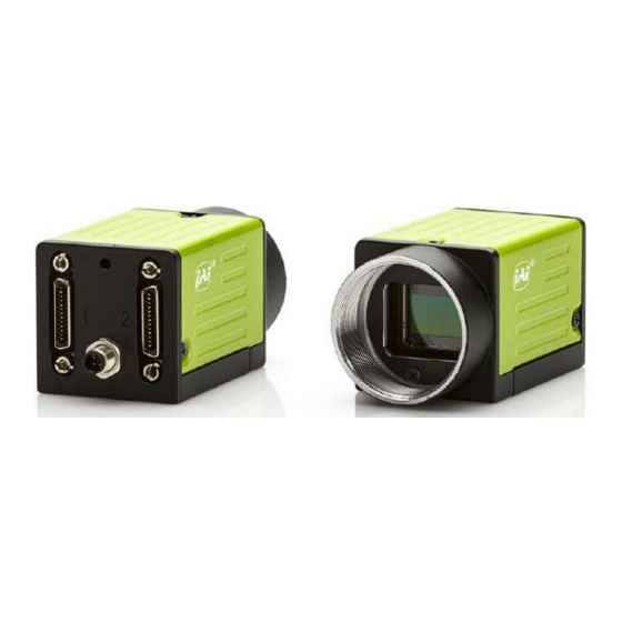
GO-2400M-PMCL-1 | GO-2400C-PMCL-1 | User Manual (Ver. 1.0) Parts Identification Parts Identification ① Lens Mount (C-Mount) ② POWER/TRIG LED ③ ④ Camera Link Connector 1 and 2 ⑤ DC IN / Trigger IN Connector (4-pin Round) ⑥ Mounting Holes (M3, 3mm depth) ①... -
Page 15: ② Power/Trig Led
GO-2400M-PMCL-1 | GO-2400C-PMCL-1 | User Manual (Ver. 1.0) Parts Identification ② POWER/TRIG LED Indicates the power or trigger input status. Status Lit amber Camera initializing. The light goes off after initiating Lit green Camera in operation in Continuous mode During operation in trigger mode, trigger signals are being input. - Page 16 GO-2400M-PMCL-1 | GO-2400C-PMCL-1 | User Manual (Ver. 1.0) Parts Identification Camera Link Connector 2 Input Signal Description Output 1, 26 Shield 2 (-), 15 (+) Y_OUT0 Data out 3 (-), 16 (+) Y_OUT1 Data out 4 (-), 17 (+) Y_OUT2...
-
Page 17: ⑤ Dc In / Trigger In Connector (4-Pin Round)
GO-2400M-PMCL-1 | GO-2400C-PMCL-1 | User Manual (Ver. 1.0) Parts Identification ⑤ DC IN / Trigger IN Connector (4-pin Round) Connect the cable for DC IN / Trigger IN here. Compatible Connectors Camera side: 09-3111-81-04 (Binder) Cable side: 79-3108-52-04 (Binder) AWG 26 79-3108-32-04 (Binder) AWG 24 Pin No. -
Page 18: Preparation
GO-2400M-PMCL-1 | GO-2400C-PMCL-1 | User Manual (Ver. 1.0) Preparation Preparation Read this section to learn how the camera connects to devices and accessories. The preparation process is described below. Step 1: Connect Devices Connect the lens, Camera Link cable, AC adapter, computer, and other devices. -
Page 19: Step 1: Connect Devices
GO-2400M-PMCL-1 | GO-2400C-PMCL-1 | User Manual (Ver. 1.0) Preparation This camera fully supports applications written using GenICam-based SDKs. The advantage of this is that programs written using GenICam names can be applied with little or no modification to control cameras with other GenICam-compliant interfaces and even GenICam compliant cameras from different vendors. -
Page 20: ① Lens
GO-2400M-PMCL-1 | GO-2400C-PMCL-1 | User Manual (Ver. 1.0) Preparation ① Lens C-mount lenses with lens mount protrusions of 9 mm or less can be attached. To prevent vignetting and to obtain the optimal resolution, use a lens that will cover the image sensor size (Type 1/1.2, 11.3mm (H) x 7.13mm (V), 13.4mm diagonal). -
Page 21: ③ Camera Link Cable
GO-2400M-PMCL-1 | GO-2400C-PMCL-1 | User Manual (Ver. 1.0) Preparation ③ Camera Link Cable Connect the Camera Link cable to the Mini Camera Link connector. Use a cable that supports the Camera Link standard and is compatible with Mini Camera Link (SDR) connectors. -
Page 22: Step 2: Verify Camera Operation
GO-2400M-PMCL-1 | GO-2400C-PMCL-1 | User Manual (Ver. 1.0) Preparation Step 2: Verify Camera Operation When power is supplied to the camera while the necessary equipment is connected, the POWER/TRIG LED at the rear of the camera lights amber, and initialization of the camera starts. -
Page 23: Step 3: Verify The Connection Between The Camera And Pc
Start Bit: 1bit Stop Bit: 1 bit Parity: None Xon/Xoff Control: None 2. Enter the command DVN? <CR><LF> from the terminal emulator software. If correctly connected, response DVN = JAI Corporation will be displayed. Item Short ASCII Command Description DVN? <CR><LF>... -
Page 24: Step 4: Change The Camera Settings
GO-2400M-PMCL-1 | GO-2400C-PMCL-1 | User Manual (Ver. 1.0) Preparation Step 4: Change the Camera Settings Related Setting Items: ImageFormatControl This section explains how to change settings by describing the procedure for changing the output format as an example. Configure the Output Format Configure the size, position, and pixel format of the images to be acquired. - Page 25 GO-2400M-PMCL-1 | GO-2400C-PMCL-1 | User Manual (Ver. 1.0) Preparation Example: Change the Width setting (ImageFormatControl) 1. To check the current Width setting, enter the command WTC?<CR><LF> from the terminal emulator software. 2. To change the Width setting to 1200, enter WTC=1200<CR><LF>.
-
Page 26: Configure Exposure And External Trigger Settings
GO-2400M-PMCL-1 | GO-2400C-PMCL-1 | User Manual (Ver. 1.0) Preparation Configure Exposure and External Trigger Settings Related Setting Items: AcquisitionControl Configure settings related to exposure control methods and trigger control. The factory settings are as follows. Change settings as necessary, according to the intended purpose or application. -
Page 27: Control Via External Triggers
GO-2400M-PMCL-1 | GO-2400C-PMCL-1 | User Manual (Ver. 1.0) Preparation Control via External Triggers When Controlling the Exposure Time Using Specified Exposure Times Configure the settings as follows. Item Setting Value / Selectable Range Trigger Selector (trigger operation) Frame Start - Trigger Mode... - Page 28 GO-2400M-PMCL-1 | GO-2400C-PMCL-1 | User Manual (Ver. 1.0) Preparation When Controlling the Exposure Time using the Pulse Width of the Trigger Input Signal Configure the settings as follows. Item Setting Value / Selectable Range Trigger Selector (trigger operation) Frame Start...
-
Page 29: Control Without External Triggers
GO-2400M-PMCL-1 | GO-2400C-PMCL-1 | User Manual (Ver. 1.0) Preparation Control Without External Triggers When Controlling the Exposure Time Using Specified Exposure Times Configure the settings as follows. Item Setting Value / Selectable Range Trigger Selector (trigger operation) Frame Start - Trigger Mode... -
Page 30: Step 5: Adjust The Image Quality
GO-2400M-PMCL-1 | GO-2400C-PMCL-1 | User Manual (Ver. 1.0) Preparation Step 5: Adjust the Image Quality Related Setting Items: AnalogControl Display the camera image and adjust the image quality. Display the Image Display the image captured by the camera. Please display the image with the viewer on the frame grabber board application. -
Page 31: Adjust The White Balance
GO-2400M-PMCL-1 | GO-2400C-PMCL-1 | User Manual (Ver. 1.0) Preparation Adjust the White Balance Related Setting Items: AnalogControl Adjust the white balance using R and B gain. The white balance can also be adjusted automatically. Notes: This function is only supported on the color model. -
Page 32: Step 6: Configuring Various Other Settings
GO-2400M-PMCL-1 | GO-2400C-PMCL-1 | User Manual (Ver. 1.0) Preparation Step 6: Configuring Various Other Settings “Short ASCII Command List” and configure settings as necessary. Step 7: Save the Settings Related Setting Items: UserSetControl The configured setting values will be deleted when the camera is turned off. By saving current setting values to user memory, you can load and recall them whenever necessary. -
Page 33: Save The User Settings
GO-2400M-PMCL-1 | GO-2400C-PMCL-1 | User Manual (Ver. 1.0) Preparation Save the User Settings 1. Stop image acquisition. Settings can only be saved when image acquisition on the camera is stopped. 2. Specify the storage location (UserSet1 - UserSet3) using the UserSetSave command and save the current camera settings. -
Page 34: Main Functions
GO-2400M-PMCL-1 | GO-2400C-PMCL-1 | User Manual (Ver. 1.0) Main Functions Main Functions This chapter describes the camera's main functions. Basic Function Matrix The combinations of settings for the basic functions that can be used together are as follows. Video Send Mode... -
Page 35: Gpio (Digital Input/Output Settings)
GO-2400M-PMCL-1 | GO-2400C-PMCL-1 | User Manual (Ver. 1.0) Main Functions GPIO (Digital Input/Output Settings) Related Setting Items: DigitalIOControl The unit can input/output the following signals to and from external input/output connectors. External output TTL Out (Line1) DC IN / trigger IN connector (4-pin round) - Page 36 GO-2400M-PMCL-1 | GO-2400C-PMCL-1 | User Manual (Ver. 1.0) Main Functions GPIO Block Diagram - 36 -...
-
Page 37: Valid Input/Output Combinations
GO-2400M-PMCL-1 | GO-2400C-PMCL-1 | User Manual (Ver. 1.0) Main Functions Valid Input/Output Combinations The following signals can be used as sources for each output destination (Trigger Selector, Line Selector, Pulse Generator Selector). You can also connect two different sources to NAND paths in the GPIO and reuse the signal generated there as a source for a different selector. -
Page 38: Camera Output Format (Tap Geometry)
GO-2400M-PMCL-1 | GO-2400C-PMCL-1 | User Manual (Ver. 1.0) Main Functions Camera Output Format (Tap Geometry) This camera supports a variety of output formats. The following tap geometries are supported. The settings on the frame grabber board must be configured to match the tap geometry setting on the camera. - Page 39 GO-2400M-PMCL-1 | GO-2400C-PMCL-1 | User Manual (Ver. 1.0) Main Functions 1X1-1Y 1X1-1Y is a 1-tap output format as defined in GenICam tap geometry. Notes: Width: 1936 pixels, 1936 pixels x 1 Taps Height: 1216 pixels - 39 -...
- Page 40 GO-2400M-PMCL-1 | GO-2400C-PMCL-1 | User Manual (Ver. 1.0) Main Functions 1X2–1Y 1X2-1Y is a 2-tap output format as defined in GenICam tap geometry. Notes: Width: 1936 pixels, 968 pixels x 2 Taps Height: 1216 pixels - 40 -...
- Page 41 GO-2400M-PMCL-1 | GO-2400C-PMCL-1 | User Manual (Ver. 1.0) Main Functions 1X3-1Y 1X3-1Y is a 3-tap output format as defined in GenICam tap geometry. Notes: Width: 1932 pixels, 644 pixels x 3 Taps Height: 1216 pixels - 41 -...
- Page 42 GO-2400M-PMCL-1 | GO-2400C-PMCL-1 | User Manual (Ver. 1.0) Main Functions 1X4–1Y 1X4-1Y is a 4-tap output format as defined in GenICam tap geometry. Notes: Width: 1936 pixels, 484 pixels x 4 Taps Height: 1216 pixels - 42 -...
- Page 43 GO-2400M-PMCL-1 | GO-2400C-PMCL-1 | User Manual (Ver. 1.0) Main Functions 1X8–1Y (CL) 1X8-1Y (CL) is a 8-tap output format as defined in GenICam tap geometry Notes: Width: 1936 pixels, 242 pixels x 8 Taps Height: 1216 pixels Cable Length Reference The following is a reference for the length of cable you can use based on the Camera Link clock.
-
Page 44: Acquisition Control (Image Acquisition Controls)
Maximum Frame Rate Period Formula Note: The Frame Rate Calculator, which calculates the maximum frame rate or trigger rate, is available for download from the product page on the JAI website (www.jai.com). About the H_Period H_Period(ms) : The value depends on TapGeometry, CL Pixel Clock and PixelFormat. - Page 45 GO-2400M-PMCL-1 | GO-2400C-PMCL-1 | User Manual (Ver. 1.0) Main Functions H_Period (ms) TapGeometry CL Pixel Clock(MHz) 8bit 10bit 12bit 37.125 6.74 6.74 1X8-1Y 74.25 4.85 6.23 84.85 4.81 6.23 Continuous Mode (Exposure Mode = Off) Calculate the maximum frame rate using the following formula.
-
Page 46: Exposure Mode
GO-2400M-PMCL-1 | GO-2400C-PMCL-1 | User Manual (Ver. 1.0) Main Functions Exposure Mode Related Setting Items: AcquisitionControl The following exposure modes are available on the camera. Exposure Description Mode Exposure control is not performed (free-running operation). Mode in which exposure time is pre-set by the user. Images can be captured with the trigger off Timed (free-running) or with trigger on (EPS). -
Page 47: Image Output Timing
GO-2400M-PMCL-1 | GO-2400C-PMCL-1 | User Manual (Ver. 1.0) Main Functions Image Output Timing Vertical Timing FVAL FVAL Total Total Frame Frame Rate PixelClock Frequency Blanking Valid FrameLine Period Geometry (Hz) [MHz] (KHz) Line [A] Line [B] (msec) (Height +40) H Freq*1000 Vertical ROI ↓... - Page 48 GO-2400M-PMCL-1 | GO-2400C-PMCL-1 | User Manual (Ver. 1.0) Main Functions Horizontal Timing Line Total Line LineValid Total Line Line Rate PixelClock Frequency Period (usec) Geometry clock [B clock [C] (KHz) [C] [MHz] (KHz) Horizontal (1936/ Tap)- Width ↓ ↓ ↓...
-
Page 49: Trigger Control
GO-2400M-PMCL-1 | GO-2400C-PMCL-1 | User Manual (Ver. 1.0) Main Functions Trigger Control The camera allows Frame Start trigger controls to be performed via external trigger signals. The Frame Start trigger allows exposure control via the trigger signal inputs. Note: The settings for exposure control and triggers are related to each other. Be sure to configure the settings described in “Configure Exposure and External Trigger... - Page 50 GO-2400M-PMCL-1 | GO-2400C-PMCL-1 | User Manual (Ver. 1.0) Main Functions Period From Period from Trigger start Period FVAL Exposure CL Pixel edge to end to next Min Exposure endTo FVAL Exposure Geometry Clock (MHz) Exposure trigger start [usec] start [B]...
- Page 51 GO-2400M-PMCL-1 | GO-2400C-PMCL-1 | User Manual (Ver. 1.0) Main Functions Trigger Overlap: Readout Period From Period from Trigger start Minimum CL Pixel Clock Min Exposure Exposure end to Tap Geometry edge to Trigger Period (MHz) (μsec) FVAL start [B] Exposure start [C](μsec)
-
Page 52: When Exposure Mode Is Trigger Width
GO-2400M-PMCL-1 | GO-2400C-PMCL-1 | User Manual (Ver. 1.0) Main Functions When Exposure Mode is Trigger Width Trigger Overlap:Off The below table indicates the shortest trigger periods for the shortest exposure times. By adding the value of the exposure time you are using to the values in the table, you can determine the shortest trigger periods under your own usage environment. - Page 53 GO-2400M-PMCL-1 | GO-2400C-PMCL-1 | User Manual (Ver. 1.0) Main Functions Period From Period from Period From Trigger start Period FVAL Exposure Trigger end CL Pixel edge to end to next Min Exposure endTo FVAL edge to Geometry Clock (MHz) Exposure...
- Page 54 GO-2400M-PMCL-1 | GO-2400C-PMCL-1 | User Manual (Ver. 1.0) Main Functions Trigger Overlap: Readout Period From Period from Minimum Period from Trigger start CL Pixel Min Exposure Exposure end Trigger Trigger end to edge to Geometry Clock (MHz) (μsec) to FVAL start...
-
Page 55: During Normal Continuous Operation
GO-2400M-PMCL-1 | GO-2400C-PMCL-1 | User Manual (Ver. 1.0) Main Functions During Normal Continuous Operation When using an application that does not require external triggers, the following applies. Shortest period [ms] Scanning range 1X2-1Y 1X3-1Y 1X4-1Y 1X8-1Y 84.85 MHz (8bit) 84.85 MHz (8bit) 84.85 MHz (8bit) - Page 56 GO-2400M-PMCL-1 | GO-2400C-PMCL-1 | User Manual (Ver. 1.0) Main Functions When Exposure Mode is set to Off Period From FVAL end Exposure stop period Tap Geometry CL Pixel Clock (MHz) to Exposure end [min] [X1] (usec) [X2] (usec) Horizontal ROI 13/H Freq ↓...
- Page 57 GO-2400M-PMCL-1 | GO-2400C-PMCL-1 | User Manual (Ver. 1.0) Main Functions When Exposure Mode is set to Timed Period From CL Pixel Clock FVAL end to Max Exposure Tap Geometry Min Exposure [usec] (MHz) Exposure end [msec] [X1] (usec) Framerate - 13/H 3H + 22 x 0.013 +...
-
Page 58: Gain Control
GO-2400M-PMCL-1 | GO-2400C-PMCL-1 | User Manual (Ver. 1.0) Main Functions Gain Control Related Setting Items: AnalogControl Analog All can be used for gain control for both the monochrome and color camera. Analog All (master gain) uses the sensor's internal gain function and consists of analog gain + digital gain. Analog gain is used for lower gain, and analog gain + digital gain is used when the gain becomes high. -
Page 59: Lut (Lookup Table)
GO-2400M-PMCL-1 | GO-2400C-PMCL-1 | User Manual (Ver. 1.0) Main Functions LUT (Lookup Table) Related Setting Items: LUT Control The LUT function is used to generate a non-linear mapping between signal values captured on the sensor and those that are output from the camera. You can specify the output curve using 256 setting points (indexes). -
Page 60: Gamma Function
GO-2400M-PMCL-1 | GO-2400C-PMCL-1 | User Manual (Ver. 1.0) Main Functions Gamma Function Note: AnalogControl The gamma function corrects the output signals from the camera beforehand (reverse correction), taking into consideration the light-emitting properties of the monitor display. As the light-emitting properties of the monitor are not linear, the entire image may be darker or the gradation in the dark areas may be less noticeable when camera outputs are displayed without processing. -
Page 61: Shading Correction
GO-2400M-PMCL-1 | GO-2400C-PMCL-1 | User Manual (Ver. 1.0) Main Functions Shading Correction Related Setting Items: JAICustomControl The shading correction is a function that corrects non-uniformity (i.e., shading) in the amount of light generated by the lens and lighting equipment. Using this function allows correction even if top, bottom, left, and right shading is not symmetrical in relation to the center of the screen (H, V). - Page 62 GO-2400M-PMCL-1 | GO-2400C-PMCL-1 | User Manual (Ver. 1.0) Main Functions Color Shading (Color model only) R-channel and B-channel properties are adjusted by using the G-channel shading properties as a reference. Cautions: The PerformShadingCalibration command cannot be executed under the following conditions.
-
Page 63: Binning Function
GO-2400M-PMCL-1 | GO-2400C-PMCL-1 | User Manual (Ver. 1.0) Main Functions Binning Function Related Setting Items: ImageFormatControl Note: This function is supported only on the monochrome model. The binning function allows you to combine the signal values of adjacent pixels in the vertical or horizontal direction (1 x 2 or 2 x 1), or in both directions simultaneously (2 x 2 binning). -
Page 64: Roi (Regional Scanning Function)
GO-2400M-PMCL-1 | GO-2400C-PMCL-1 | User Manual (Ver. 1.0) Main Functions ROI (Regional Scanning Function) Related Setting Items: ImageFormatControl The ROI (region of interest) function allows you to output images by specifying the areas to scan. ROI Settings Specify the area to scan by specifying width, height, and horizontal/vertical offset values under... -
Page 65: Video Send Mode
GO-2400M-PMCL-1 | GO-2400C-PMCL-1 | User Manual (Ver. 1.0) Main Functions Video Send Mode Switch the video send mode to configure and operate Sequence Trigger and other JAI Custom Control functions. Select the video send mode in Video Send Mode Selector. -
Page 66: Trigger Sequencer Mode
GO-2400M-PMCL-1 | GO-2400C-PMCL-1 | User Manual (Ver. 1.0) Main Functions Trigger Sequencer mode With this mode, the Sequencer Trigger “pattern” is predetermined by the user. The user defines up to 128 different “indexes.” Each index represents a combination of the following parameters:... - Page 67 GO-2400M-PMCL-1 | GO-2400C-PMCL-1 | User Manual (Ver. 1.0) Main Functions Trigger Sequencer Example User-Defined Indexes (up to 128) Index Structure for Trigger Sequencer - 67 -...
-
Page 68: Command Sequencer Mode
GO-2400M-PMCL-1 | GO-2400C-PMCL-1 | User Manual (Ver. 1.0) Main Functions Command Sequencer Mode This mode allows the user to vary the “pattern” of the sequence in response to external factors. Changes in the sequence can be initiated manually or in a programmatic fashion as the result of data from sensors/controllers or from the analysis of previous images. - Page 69 GO-2400M-PMCL-1 | GO-2400C-PMCL-1 | User Manual (Ver. 1.0) Main Functions Command Sequencer Example User-defined Indexes (up to 128) Index Structure for Command Sequencer - 69 -...
-
Page 70: Sensor Multi Roi Function
GO-2400M-PMCL-1 | GO-2400C-PMCL-1 | User Manual (Ver. 1.0) Main Functions Sensor Multi ROI Function Sensor Multi ROI is an ROI function that is configured and functions inside the sensor. You can configure up to 16 scanning regions (4 horizontal and 4 vertical). By skipping areas that are not specified as regions of interest when scanning a frame, the sensor's ROI function outputs the specified regions in a compressed state. -
Page 71: Configuration
GO-2400M-PMCL-1 | GO-2400C-PMCL-1 | User Manual (Ver. 1.0) Main Functions Configuration Configure each area so that they do not overlap. Both the horizontal and vertical settings must be configured as even values. Horizontal ROI conditions ROI Offset H1 + ROI Width1 < ROI Offset H2 ROI Offset H2 + ROI Width2 <... - Page 72 GO-2400M-PMCL-1 | GO-2400C-PMCL-1 | User Manual (Ver. 1.0) Main Functions Reference: Areas corresponding to the Horizontal Enable and Vertical Enable settings of each setting Index 1 Index 2 Index 3 Index 4 Enabled Enabled Area Hori Vert Hori Vert Hori...
- Page 73 GO-2400M-PMCL-1 | GO-2400C-PMCL-1 | User Manual (Ver. 1.0) Main Functions Frame Rate Calculation Formula FR =Line Rate ÷ (ROI Height 1 + ROI Height 2 + ROI Height 3 + ROI Height 4 +vertical invalid lines) Invalid vertical lines = 40 (constant) The value of Line Rate depends on tap geometry and Camera Link pixel clock frequency as shown in the following table.
-
Page 74: Alc (Automatic Level Control)
GO-2400M-PMCL-1 | GO-2400C-PMCL-1 | User Manual (Ver. 1.0) Main Functions ALC (Automatic Level Control) Related Setting Items: JAICustomControl The ALC (automatic level control) function combines the automatic gain control (AGC/Auto Gain Control) and automatic exposure control (ASC/Auto Shutter Control) functions, and is capable of handling various changes in brightness. -
Page 75: Detailed Settings For Gain Auto (Automatic Gain Level Control)
GO-2400M-PMCL-1 | GO-2400C-PMCL-1 | User Manual (Ver. 1.0) Main Functions Detailed Settings for Gain Auto (Automatic Gain Level Control) When Gain Auto is set to Continuous, you can configure the conditions for automatic adjustment in detail. Item Description Specify the target level for automatic gain control. (This setting is also used for automatic ALC Reference exposure control.) -
Page 76: Counter And Timer Control
GO-2400M-PMCL-1 | GO-2400C-PMCL-1 | User Manual (Ver. 1.0) Main Functions Counter and Timer Control Related Setting Items: Counter and Timer Control Note: This camera supports the Counter function only. The counter function counts up change points in the camera’s internal signals using the camera’s internal counter, and reads that information from the host side. - Page 77 GO-2400M-PMCL-1 | GO-2400C-PMCL-1 | User Manual (Ver. 1.0) Main Functions Internal Camera Blocks To Use the Counter Function Configure the settings as follows. Three counters can be configured (Counter 0 to 2). Item Setting Value / Selectable Range Description Counter 0 ~ 2 Counter 0 ~ 2 Select the counter.
-
Page 78: Video Process Bypass Mode
GO-2400M-PMCL-1 | GO-2400C-PMCL-1 | User Manual (Ver. 1.0) Main Functions Video Process Bypass Mode Related Setting Items: JAICustomControl The video process bypass mode is a function that bypasses internal video processing on the camera. When bypass is enabled, the sensor output and camera output data can be set to the same bit width. -
Page 79: Setting List (Feature Properties)
GO-2400M-PMCL-1 | GO-2400C-PMCL-1 | User Manual (Ver. 1.0) Setting List (Feature Properties) Setting List (Feature Properties) DeviceControl Display/configure information related to the device. DeviceControl Setting Default Description Item Range Device Vendor Name “JAI Ltd., Japan” Display the manufacturer name. Device Model Name Display the model name. -
Page 80: Imageformatcontrol
GO-2400M-PMCL-1 | GO-2400C-PMCL-1 | User Manual (Ver. 1.0) Setting List (Feature Properties) ImageFormatControl Configure image format settings. Image Format Setting Range Default Description Control Item Sensor Width 1936 1936 Display the maximum image width. Sensor Height 1216 1216 Display the maximum image height. - Page 81 GO-2400M-PMCL-1 | GO-2400C-PMCL-1 | User Manual (Ver. 1.0) Setting List (Feature Properties) Image Format Setting Range Default Description Control Item Set the vertical offset. Model Height Max Step Mono 1214 (607) 2 (1)pixels Offset Y Color 1214 2 pixels For the monochrome model, the parenthesis value applies when BinningHorizontal is set to 2.
-
Page 82: Acquisitioncontrol
GO-2400M-PMCL-1 | GO-2400C-PMCL-1 | User Manual (Ver. 1.0) Setting List (Feature Properties) AcquisitionControl Related Topic: Acquisition Control (Image Acquisition Controls), Exposure Mode, Trigger Control Configure image capture settings. Acquisition Setting Range Default Description Control Item Set the frame rate as a frequency. (unit: Hz) The Acquisition Frame Rate 0.125 ~ 127.975... -
Page 83: Digitaliocontrol
GO-2400M-PMCL-1 | GO-2400C-PMCL-1 | User Manual (Ver. 1.0) Setting List (Feature Properties) DigitalIOControl Related Topic: GPIO (Digital Input/Output Settings) Configure settings for digital input/output. Digital IO Control Setting Range Default Description Item Line1 - TTL Out Line4 - TTL In... -
Page 84: Analogcontrol
GO-2400M-PMCL-1 | GO-2400C-PMCL-1 | User Manual (Ver. 1.0) Setting List (Feature Properties) AnalogControl Related Topic: Gain Control, Gamma Function Configure analog control settings. Analog Control Setting Range Default Description Item Analog All Digital Red All* Analog All Gain Selector Select the gain to configure. -
Page 85: Pulsegenerators
GO-2400M-PMCL-1 | GO-2400C-PMCL-1 | User Manual (Ver. 1.0) Setting List (Feature Properties) PulseGenerators Related Topic: GPIO (Digital Input/Output Settings) Configure pulse generator settings. Pulse Generators Setting Range Default Description Item Set the division value for the prescaler (12-bit) using the... -
Page 86: Lut Control
GO-2400M-PMCL-1 | GO-2400C-PMCL-1 | User Manual (Ver. 1.0) Setting List (Feature Properties) Pulse Generators Setting Range Default Description Item High Level Pulse Generator Clear Set the clear signal condition for the count clear input of the Low Level 0: Off Activation pulse generator. -
Page 87: Transport Layer Control
GO-2400M-PMCL-1 | GO-2400C-PMCL-1 | User Manual (Ver. 1.0) Setting List (Feature Properties) Transport Layer Control Related Topic: Camera Output Format (Tap Geometry) Configure Camera Link Transport Layer settings. Transport Layer Setting Range Default Description Control Item Geometry_1X1_1Y Geometry_1X2_1Y Geometry_ Set the transmission method for each time images are... -
Page 88: Jaicustomcontrol
GO-2400M-PMCL-1 | GO-2400C-PMCL-1 | User Manual (Ver. 1.0) Setting List (Feature Properties) JAICustomControl Configure settings for functions that are unique to JAI cameras and not specified by SFNC. JAI Custom Setting Range Default Description Control Item Video Process Bypass Mode Enable/ disable video process bypass mode. - Page 89 GO-2400M-PMCL-1 | GO-2400C-PMCL-1 | User Manual (Ver. 1.0) Setting List (Feature Properties) JAI Custom Setting Range Default Description Control Item ALC Reference Related Topic: 10 ~ 95 Set the target level for ALC. (unit: %) ALC (Automatic Level Control) Low Right...
- Page 90 GO-2400M-PMCL-1 | GO-2400C-PMCL-1 | User Manual (Ver. 1.0) Setting List (Feature Properties) JAI Custom Setting Range Default Description Control Item Low Right Low Mid-Right Low Mid-Left Low Left Mid-Low Right Mid-Low Mid-Right Mid-Low Mid-Left Mid-Low Left AWB Area Selector Low Right Select the area for which to configure AWB Area Enable.
- Page 91 GO-2400M-PMCL-1 | GO-2400C-PMCL-1 | User Manual (Ver. 1.0) Setting List (Feature Properties) JAI Custom Setting Range Default Description Control Item Sequence Roi Offset Y 0 ~ 1214 Set the Offset Y of the selected Sequence Roi Index. Set the Horizontal Binning of the selected Sequence Roi Sequence Roi V Binning 1 ~ 2 Index.
-
Page 92: Counter And Timer Control
GO-2400M-PMCL-1 | GO-2400C-PMCL-1 | User Manual (Ver. 1.0) Setting List (Feature Properties) Counter and Timer Control Related Topic: Counter and Timer Control Configure counter settings. (This camera only supports counter functions.) Counter and Timer Control Setting Range Default Description Item... - Page 93 GO-2400M-PMCL-1 | GO-2400C-PMCL-1 | User Manual (Ver. 1.0) Setting List (Feature Properties) Counter and Timer Control Setting Range Default Description Item Counter2 Event RisingEdge [Rising Edge] Display the timing at which to count. Activation FallingEdge [Falling Edge] Counter2 Reset Reset the counter.
-
Page 94: Short Ascii Command List
GO-2400M-PMCL-1 | GO-2400C-PMCL-1 | User Manual (Ver. 1.0) Short ASCII Command List Short ASCII Command List All configuration of the camera is done via the RS-232C port. The camera can be set up from a PC running terminal emulator software. - Page 95 GO-2400M-PMCL-1 | GO-2400C-PMCL-1 | User Manual (Ver. 1.0) Short ASCII Command List Transmit the Request Command to Camera The status of camera's settings can be queried by transmitting NN?<CR><LF>, where NN is any valid command. The camera will return the current setting data.
-
Page 96: Gencp Bootstrap Register (Short Ascii Command)
GO-2400M-PMCL-1 | GO-2400C-PMCL-1 | User Manual (Ver. 1.0) Short ASCII Command List GenCP Bootstrap Register (Short ASCII Command) Short Name Access Values Default Description ASCII DVN?<CR><LF> DeviceVendorName "JAI Ltd., Japan" Display the manufacture name. MD?<CR><LF> GO-2400C-PMCL-1 DeviceModelName GO-2400M-PMCL-1 Display the model name. -
Page 97: Device Control (Short Ascii Command)
GO-2400M-PMCL-1 | GO-2400C-PMCL-1 | User Manual (Ver. 1.0) Short ASCII Command List Device Control (Short ASCII Command) Interface Name Short ASCII Values Default Description Access VN?<CR><LF> DeviceFirmware Version Firm Ver. No. Display the firmware version. CRS00=1<CR><LF> DeviceReset CRS00 Reset the device. - Page 98 GO-2400M-PMCL-1 | GO-2400C-PMCL-1 | User Manual (Ver. 1.0) Short ASCII Command List Short Name Access Values DEFAULT Description ASCII OFL=[Param.]<CR><LF> OFL?<CR><LF> (2 line/ Step) Set the vertical offset. (The value will be set in configuration steps) OffsetY OFL Min ~ (Max – Height)
-
Page 99: Acquisition Control (Short Ascii Command)
GO-2400M-PMCL-1 | GO-2400C-PMCL-1 | User Manual (Ver. 1.0) Short ASCII Command List Short Name Access Values DEFAULT Description ASCII Monochrome Model 0: Mono8 1: Mono10 BA=[Param.]<CR><LF> 2: Mono12* BA?<CR><LF> Color Model PixelFormat R/(W) 0: BayerRG8 Set the pixel format. Mono12, BayerRG12 and... - Page 100 GO-2400M-PMCL-1 | GO-2400C-PMCL-1 | User Manual (Ver. 1.0) Short ASCII Command List Short Name Access Values DEFAULT Description ASCII 0: Low 1: High 2: SoftTrigger 8: PulseGenerator0 TI=[Param.]<CR><LF> 10:UserOutput0 TI?<CR><LF> FrameStartTrigSource 11:UserOutput1 12: TTL_In1 Select the trigger signal source. (Std Only)
-
Page 101: Digital Io Control (Short Ascii Command)
GO-2400M-PMCL-1 | GO-2400C-PMCL-1 | User Manual (Ver. 1.0) Short ASCII Command List Digital IO Control (Short ASCII Command) Short Name Access Values DEFAULT Description ASCII LI0=[Param.]<CR><LF> 0: False LI0?<CR><LF> LineInverter_TTLOut 1: True Enable/disable polarity inversion for the TTL output. ND0INV1=[Param.]<CR><LF>... -
Page 102: Analog Control (Short Ascii Command)
GO-2400M-PMCL-1 | GO-2400C-PMCL-1 | User Manual (Ver. 1.0) Short ASCII Command List Short Name Access Values DEFAULT Description ASCII USC0=[Param.]<CR><LF> 0: False USC0?<CR><LF> UserOutput0 USC0 1: True Set the User Output0 value. USC1=[Param.]<CR><LF> 0: False USC1?<CR><LF> UserOutput1 USC1 1: True Set the User Output1 value. -
Page 103: Lut Control (Short Ascii Command)
GO-2400M-PMCL-1 | GO-2400C-PMCL-1 | User Manual (Ver. 1.0) Short ASCII Command List Short Name Access Values DEFAULT Description ASCII 0: Off 1: Once AWB=[Param.]<CR><LF> 2: Continuous AWB?<CR><LF> BalanceWhiteAuto 3: 4600K 4: 5600K Set the auto white balance mode. Color model only. -
Page 104: User Set Control (Short Ascii Command)
GO-2400M-PMCL-1 | GO-2400C-PMCL-1 | User Manual (Ver. 1.0) Short ASCII Command List User Set Control (Short ASCII Command) Short Name Access Values Default Description ASCII 0: Default LD=[Param.]<CR><LF> 1: UserSet1 LD?<CR><LF> UserSetLoad (R)/W 2: UserSet2 Load user settings. 3: UserSet3 SA=[Param.]<CR><LF>... -
Page 105: Jai Custom (Short Ascii Command)
GO-2400M-PMCL-1 | GO-2400C-PMCL-1 | User Manual (Ver. 1.0) Short ASCII Command List Short Name Access Values Default Description ASCII CV1?<CR><LF> Counter1Value 0 ~ 65535 Display the Counter1 value. CV2?<CR><LF> Counter2Value 0 ~ 65535 Display the Counter2 value. JAI Custom (Short ASCII Command) - Page 106 GO-2400M-PMCL-1 | GO-2400C-PMCL-1 | User Manual (Ver. 1.0) Short ASCII Command List Short Name Access Values Default ASCII BMPYW=[Param1], [Param2]<CR><LF> Param 1: Blemish BMPYW? [Param1]<CR><LF> index (0 ~ 255) Display the Y coordinate (vertical BlemishWhiteDetect BMPYW pixel position) of the blemish PositionY selected in Blemish Data Index.
- Page 107 GO-2400M-PMCL-1 | GO-2400C-PMCL-1 | User Manual (Ver. 1.0) Short ASCII Command List Short Name Access Values Default ASCII SQNI n=[Param.]<CR><LF> SQNI n?<CR><LF> SequenceModeNext Index n Set the index to be executed after SQNIn 1 ~ 128 Sequence Roi Index n. (Only...
- Page 108 GO-2400M-PMCL-1 | GO-2400C-PMCL-1 | User Manual (Ver. 1.0) Short ASCII Command List Short Name Access Values Default ASCII SQVB n=[Param.]<CR><LF> SequenceMode SQVB n?<CR><LF> 1: Vbinning = OFF Vbinningn SQVBn Set the vertical binning of 2: Vbinning = x2* n = 1 ~ 128 Sequence Roi Index n.
- Page 109 GO-2400M-PMCL-1 | GO-2400C-PMCL-1 | User Manual (Ver. 1.0) Short ASCII Command List Short Name Access Values Default ASCII SQLUT=[Param.]<CR><LF> SQLUT?<CR><LF> Select the LUT mode to use during 0: Gamma SequenceLutMode SQLUT Trigger Sequence Mode and 1: LUT Command Sequence Mode. (This setting is applied when Sequence Roi Lut Enable is set to ”True”.)
- Page 110 GO-2400M-PMCL-1 | GO-2400C-PMCL-1 | User Manual (Ver. 1.0) Short ASCII Command List Short Name Access Values Default ASCII ALCS=[Param.]<CR><LF> ALCS?<CR><LF> AlcSpeed ALCS 1 ~ 8 Set the control speed for AGC and ASC. (8 is the fastest.) AWBSU=[Param.]<CR><LF> AWBSU?<CR><LF> AwbSpeed...
- Page 111 GO-2400M-PMCL-1 | GO-2400C-PMCL-1 | User Manual (Ver. 1.0) Short ASCII Command List Short Name Access Values Default ASCII ALCA=[Param.]<CR><LF> ALCA?<CR><LF> On: Specify all photometry areas for ALC, regardless of the enabled/disabled statuses configured individually for each 0: OFF ALCChannelAreaAll ALCA...
- Page 112 GO-2400M-PMCL-1 | GO-2400C-PMCL-1 | User Manual (Ver. 1.0) Short ASCII Command List Short Name Access Values Default ASCII AWBA=[Param.]<CR><LF> AWBA?<CR><LF> On: Specify all photometry areas for AWB, regardless of the enabled/disabled statuses 0: OFF configured individually for each 1: ON...
- Page 113 GO-2400M-PMCL-1 | GO-2400C-PMCL-1 | User Manual (Ver. 1.0) Short ASCII Command List Short Name Access Values Default ASCII AR=[Param.]<CR><LF> AR?<CR><LF> Not required. Acquisition Frame AcquisitionFrameLine 1 ~ 325786 Period exists. Maximum value is calculated depending on Height and Offset Y settings 0(γ=0.45)/1...
- Page 114 GO-2400M-PMCL-1 | GO-2400C-PMCL-1 | User Manual (Ver. 1.0) Short ASCII Command List Short Name Access Values Default ASCII PGRPT0=[Param.]<CR><LF> PGRPT0?<CR><LF> GpioPulseGen Set the repeat count for the PGRPT0 0 ~ 255 RepeatCount0 counter. When this is set to 0, the counter will be free-running with limitless repeating.
- Page 115 GO-2400M-PMCL-1 | GO-2400C-PMCL-1 | User Manual (Ver. 1.0) Short ASCII Command List Short Name Access Values Default ASCII 0:Low 1:High 3: FrameTriggerWait 4: FrameActive 5: ExposureActive ND0IN1=[Param.]<CR><LF> 6: Fval ND0IN1?<CR><LF> GpioNand0 7:LVAL ND0IN1 InputSource1 8: PulseGenerator0 Select the input source signal for 10:UserOutput0 NAND0 In1.
- Page 116 GO-2400M-PMCL-1 | GO-2400C-PMCL-1 | User Manual (Ver. 1.0) Short ASCII Command List Short Name Access Values Default ASCII ND1INV1=[Param.]<CR><LF> ND1INV1?<CR><LF> 0: Non-Inv GpioNand1 ND1INV1 InputInvert1 1: Inv Not required. LineInverter_ Nand1In1 exists. ND0INV2=[Param.]<CR><LF> ND0INV2?<CR><LF> 0: Non-Inv GpioNand0 ND0INV2 InputInvert2 1: Inv Not required.
- Page 117 GO-2400M-PMCL-1 | GO-2400C-PMCL-1 | User Manual (Ver. 1.0) Short ASCII Command List Short Name Access Values Default ASCII BGOE =[Param.]<CR><LF> 0: OFF BGOE?<CR><LF> 1: ON BINNING_GAIN_EN BGOE Set whether to apply gain to the Mono model only image during horizontal binning mode.
-
Page 118: Miscellaneous
Miscellaneous Miscellaneous Troubleshooting Check the following before requesting help. If the problem persists, contact your local JAI distributor. Power Supply and Connections Issue: The POWER/TRIG LED remains lit amber and does not turn green, even after power is supplied to the camera. -
Page 119: Specifications
GO-2400M-PMCL-1 | GO-2400C-PMCL-1 | User Manual (Ver. 1.0) Miscellaneous Specifications Item GO-2400M-PMCL-1 GO-2400C-PMCL-1 Scanning system Progressive scan Synchronization Internal Interface CameraLink (Version 2.0) Image sensor 1/1.2-inch monochrome CMOS 1/1.2-inch Bayer color CMOS Image size (effective 11.3mm x 7.13mm (13.4mm diagonal) - Page 120 GO-2400M-PMCL-1 | GO-2400C-PMCL-1 | User Manual (Ver. 1.0) Miscellaneous Item GO-2400M-PMCL-1 GO-2400C-PMCL-1 Trigger Overlap Off / Read out Trigger Input Signals Line4 - TTL In、 Software、 PG0、 NAND Out0/1 Timed: 28.7 μs (8-bit), 32.7 μs (10-bit) (min)*2 to 8 s (max), variable unit: 1 μs TriggerWidth: 28.7 μs (8-bit), 32.7 μs (10-bit) (min)*2 to ∞...
- Page 121 GO-2400M-PMCL-1 | GO-2400C-PMCL-1 | User Manual (Ver. 1.0) Miscellaneous Item GO-2400M-PMCL-1 GO-2400C-PMCL-1 C-mount Lens mount Lens mount protrusion length of 9 mm or less is supported Flange back 17.526, tolerance: 0 mm to –0.05 m Optical filter (IR cut filter)
-
Page 122: Frame Rate Reference
GO-2400M-PMCL-1 | GO-2400C-PMCL-1 | User Manual (Ver. 1.0) Miscellaneous Frame Rate Reference Theoretical value: decimal values are dropped, during Unpacked Resolution Frame Rate Pixel Count ROI/Binning Pixel Size (µm) Image Size (Screen Size) 8 / 10 / 12 bit 2.35 MP 1936 ×... -
Page 123: Spectral Response
GO-2400M-PMCL-1 | GO-2400C-PMCL-1 | User Manual (Ver. 1.0) Miscellaneous Spectral Response GO-2400M-PMCL-1 GO-2400C-PMCL-1 - 123 -... -
Page 124: Dimensions
GO-2400M-PMCL-1 | GO-2400C-PMCL-1 | User Manual (Ver. 1.0) Miscellaneous Dimensions Notes: Dimensional tolerance: ± 0.3mm Unit: mm - 124 -... -
Page 125: User's Record
GO-2400M-PMCL-1 | GO-2400C-PMCL-1 | User Manual (Ver. 1.0) Miscellaneous User's Record Model name: …………… Revision: …………… Serial No: …………… Firmware version: …………… For camera revision history, please contact your local JAI distributor. - 125 -... -
Page 126: Revision History
GO-2400M-PMCL-1 | GO-2400C-PMCL-1 | User Manual (Ver. 1.0) Revision History Revision History Revision Date Device Version Changes 2023/06/19 DV0100 First Release Trademarks Other systems and product names described in this document are trademarks or registered trademarks of their respective owners. The ™ and ®...
Need help?
Do you have a question about the GO-2400M-PMCL-1 and is the answer not in the manual?
Questions and answers