RMG TME400-VM VMF Series Operating Manual
Turbine meter
Hide thumbs
Also See for TME400-VM VMF Series:
- Operating manual (98 pages) ,
- Operating manual (154 pages)

Related Manuals for RMG TME400-VM VMF Series


Summary of Contents for RMG TME400-VM VMF Series
- Page 1 Operating Manual Turbine Meter TME400-VM (..-VMF) Stand: 07.12.2020 Version: Firmware: 1.06...
- Page 2 Contact Manufacturer Contact our customer service department for tech- nical information. Address RMG Messtechnik GmbH Otto-Hahn-Straße 5 D-35510 Butzbach (Ger- many) Main office +49 6033 897 – 0 Service +49 6033 897 – 0 Spare parts +49 6033 897 – 173 +49 6033 897 –...
-
Page 3: Table Of Contents
Contents TABLE OF CONTENTS INTRODUCTION ..........................1 STRUCTURE OF THE MANUAL ....................1 1.1. PURPOSE OF THE MANUAL ....................2 1.2. ABBREVIATIONS ........................2 1.2.1. SYMBOLS ..........................3 1.2.2. STRUCTURE OF NOTICES ....................3 1.2.3. WORKING WITH THE DEVICE ....................4 1.2.4. - Page 4 CONTENTS INTEGRATING THE TURBINE METER INTO THE PIPELINE ......... 22 1.4.2. SEALS ..........................22 1.4.2.1. SCREWS ..........................25 1.4.2.2. METER HOUSING MATERIAL ..................25 1.4.2.3. INSTALLATION ......................... 26 1.4.2.4. THRESHOLD VALUES ..................... 27 1.4.2.5. TECHNICAL GUIDELINE G13 ..................29 1.4.2.6. STANDARDS / GUIDELINES ...................
- Page 5 Contents VOLUME / METERS ......................58 4.3.3.1. FLOW RATE ........................60 4.3.3.2. CURRENT OUTPUT ......................61 4.3.3.3. ERROR / TYPE PLATE ..................... 62 4.3.3.4. RS-485 INTERFACE ......................63 4.3.3.5. ARCHIVE ..........................64 4.3.3.6. SETTINGS .......................... 66 4.3.3.7. RMGVIEW ..........................69 4.4.
- Page 6 CONTENTS SEAL DIAGRAMS ........................102 LATER INSTALLATION OF THE POWER MODULE .............. 103 CERTIFICATES AND APPROVALS ..................105 Manual TME400-VMF · EN07 · December, 7 2020...
-
Page 7: Introduction
1 Introduction 1. Introduction 1.1. Structure of the manual The introduction of this manual comprises two parts. The first part lists general speci- fications; the symbols used in the manual and the structure of notices are presented and a risk assessment is provided. The differences between the TME400-VM and TME400-VMF turbine meters are explained. -
Page 8: Purpose Of The Manual
1 Introduction 1.2. Purpose of the manual This manual provides information that is necessary for fault-free and safe operation. The TME400 was designed and produced according to the state of the art and gener- ally recognized safety standards and directives. However, its use can entail dangers that are avoidable by complying with this manual. -
Page 9: Symbols
1 Introduction MessEG Measurement and Calibration Act Law on the marketing and provision of measuring devices in the market, their use and calibration, valid since 1/1/2015 MessEV Measurement and Calibration Regulation Regulation on the marketing and provision of measuring devices in the market and on their use and calibration;... -
Page 10: Working With The Device
1 Introduction Warning This warning notice informs you of potentially dangerous situations that can arise due to misuse/operator error. If these situations are not avoided, minor injuries can occur. Caution This notice informs you of potentially dangerous situations that can arise due to misuse/operator error. - Page 11 Caution All notices in the manual must be observed. Use of the TME400 is only per- mitted in accordance with the specifications in the operating manual. RMG assumes no liability for damages arising due to disregard of the operating manual.
-
Page 12: Dangers During Commissioning
Dangers during commissioning 1.2.4.2. Initial commissioning The initial commissioning must only be carried out by specially trained personnel (training by RMG) or RMG service personnel. Note An acceptance test certificate must be created during the commissioning. This, the operating manual and the EU Declaration of Conformity must be stored so that they are always readily available. -
Page 13: Dangers During Maintenance And Repair
The descriptions in the operating manual must be observed. In general, it is recommended that the replacement should only be carried out by RMG Service. A leak test must be carried out after work on pressurized components. - Page 14 1 Introduction Maintenance personnel Work on the device must only be carried out by qualified personnel who can carry out the respective tasks on the basis of their technical training, experience and familiarity with the applicable standards and requirements. These qualified personnel are familiar with the applicable statu- tory regulations for accident prevention and can inde- pendently recognize and avoid potential dangers.
-
Page 15: Qualification Of Personnel
Risk assessment and minimization 1.2.5. According to assessment by qualified employees of RMG, the TME400 is subject to risks during its use. Risks can arise, for example, due to high pressures and occa- sionally due to pressures that are too low. Work outside of the permissible tempera- ture range can also lead to dangers. - Page 16 1 Introduction Non-destructive testing was also carried out: X-ray and ultrasonic inspection of the meter housing for defective points in material, surface crack testing with mag- netic powder and a color penetration process Strength tests for components were conducted at 1.5 times the nominal pressure for the pressure testing;...
- Page 17 1 Introduction Danger The following applies for work in hazardous areas (all zones): The pulse generators of the turbine meter must be connected to intrin- sically safe power circuit only. Only tools that are approved for Ex Zone 1 are permitted for mainte- nance and repair tasks.
-
Page 18: Applicability Of The Manual
This manual describes the TME400. TME400 is generally only part of a complete system. The manuals of the other components of the system must be observed. If you find contradictory instructions, contact RMG and/or the manufacturers of the other components. -
Page 19: Responsibility Of The Operator
1 Introduction Responsibility of the operator 1.2.6.3. As the operator, you must ensure that only adequately qualified personnel work on the device. Ensure that all employees who work with the device have read and un- derstood this manual. You are also obligated to train personnel regularly and inform them of the dangers. -
Page 20: Scope Of Delivery
1 Introduction Warning Risk of injury during transport Any foot screws must be mounted if they are provided as a transport safe- guard to prevent rolling and tipping. Additional measures must be taken to ensure that impermissible rolling and tipping are prevented. Only use the provided lifting eyes / ring screws to lift the meter. -
Page 21: Disposal Of Packaging Material
Avoid extended periods of storage. After storage, inspect the device for damage and test for correct function. Contact the RMG service department to arrange for inspec- tion of the device after a storage period of longer than one year. For this purpose, re- turn the device to RMG. -
Page 22: Overview Of Versions
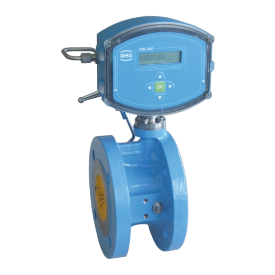
1 Introduction 1.3. Overview of versions Description 1.3.1. The TME400-VM is a turbine meter which is used for volume measurement of the op- erating volume of non-aggressive gases and burnable gas. The operating volume flow is determined based on the turbine speed, which is scanned by means of a Wie- gand or Reed sensor element and then added together in internal archives. -
Page 23: Power Supply
1 Introduction TME400-VMF In addition to the features of the TME400 VM, this version can be used for custody- transfer applications. Power supply 1.3.3. Battery-operated device The TME400 is equipped with a replaceable 3.6 V lithium battery. The device is designed for continuous operation for approximately 10 years. -
Page 24: Installation And Mounting Position
The EC type approval certificate is: TÜV 17 ATEX 207566 X IECEx TUN 18.0009 X The corresponding conformity certificates are provided in the annex. The RMG con- tact information is provided on the second and last page. 1.3.4.1. Installation and mounting position The TME400-VM and TME400-VMF can be supplied with DIN and ANSI connec- tions. -
Page 25: Use Of Gas Meters For Different Gases
1 Introduction Note If different temperature ranges apply simultaneously, the smallest specified range applies for the overall system. This is also marked on the type plate. 1.3.5. Use of gas meters for different gases Symbol Tight- Meter Comments ness at housing 0°C and 1.013 bar... -
Page 26: Suitability And Compatibility For Natural Gas Containing H
Not custody transfer measurements are of course possible in natural gases with a hy- drogen content above 10 mol%. However, a reduced measuring range must be taken into account if applicable. Please contact RMG for further information. 1.4. Areas of application The following chapter provides handling instructions for the TME400 turbine meter for the purpose of safe and reliable operation of the device. - Page 27 1 Introduction Flow straightener 7 Sensor Sensor sleeve 8 Permanent magnet O-ring 9 Pressure connection Counter 10 Turbine wheel Clamp screw 11 Oil pump Thermowell for temperature comparison (fiscal) Figure 1: Turbine meter sectional drawing There is a permanent magnet on the end disc of the turbine shaft which induces a voltage pulse in the Wiegand sensor with every rotation.
-
Page 28: Integrating The Turbine Meter Into The Pipeline
Integrating the turbine meter into the pipeline 1.4.2. Turbine meters from RMG are equipped with connecting flanges. For a secure con- nection, the connection dimensions of the flanges of the pipelines to be connected must match the connection dimensions of the flanges of the device. - Page 29 1 Introduction 4" 6" 8" 10" 12" 16" 20" 24" Grooved seals (EN 12560-6 with centering ring) ANSI 300 / ANSI 600 PN 64 2" 69.8 88.9 3" 98.4 123.8 4" 123.8 154.0 6" 177.8 212.7 8" 228.6 266.7 10" 282.6 320.7 12"...
- Page 30 1 Introduction ANSI 300 PN 64 ANSI 600 2" 69.9 85.9 69.9 85.9 3" 101.6 120.7 101.6 120.7 4" 106.4 127.0 149.4 106.4 120.7 149.4 6" 157.2 182.6 209.6 157.2 174.8 209.6 8" 215.9 233.4 263.7 215.9 225.6 263.7 10" 268.3 287.3 317.5...
-
Page 31: Screws
1 Introduction Screws 1.4.2.2. Temperature ranges for screws and nuts -10°C to +80°C -40°C to +80°C Pressure Option 1 Option 2 Option 3 levels up to and Screws according to Screws according to including DIN EN ISO 4014 DIN EN ISO 4014 40 bar in material 5.6 in material 25CrMo4,... -
Page 32: Installation
If there is pertubation (e.g. a gas pressure control device) upstream from the inlet pipe, a perforated plate straightener is also necessary. Perforated plate straightener according to ISO 5167-1 or the type RMG LP-35, which cause a pressure loss by a factor of 2.5 in comparison with the standard straightener, can be used. -
Page 33: Threshold Values
1 Introduction Danger Protect the turbine meter from damage caused by high pressure changes fluctuations in the flow, e.g. if the downstream pipeline system is filled or blown off. Danger Welding on the line must only take place at a safe distance from the meter. Extreme temperatures in the line near the meter can cause permanent dam- age to the meter. - Page 34 1 Introduction Note Maximum overload < 20% above Q , short-term (< 30 sec) = ˆ Maximum flow rate changes and/or < 0.01·Q /sec 1% of Q /sec impact loads e.g. start-up 0 - 100%: > 100 sec Maximum pressure change: <...
-
Page 35: Technical Guideline G13
1 Introduction Technical guideline G13 1.4.2.6. The installation conditions for new systems according to TRG G13 and the facilitated installation conditions for RMG turbine meters are compared in the table below. Type of up- Installation Installation Comments stream per- conditions... -
Page 36: Standards / Guidelines
2 - 15 (c² r / 2) Dynamic pressure loss Dp With the RMG turbine meters, these straighteners fulfill the requirements of technical guideline G 13 and are approved with approval number D 81 / 7.211.10 for turbine meters. Standards / guidelines 1.4.2.7. -
Page 37: Measuring Ranges
1 Introduction Measuring ranges 1.4.2.8. Type TME400 turbine meters have measuring ranges of at least 1:20 at atmospheric pressure (see chapter 1.4.2.9 Measuring accuracy). At a higher pressure, the meas- uring range can be expanded to 1:50. The measuring ranges are between 2.5 and 25,000 m /h (operating conditions), depending on meter size. -
Page 38: Measuring Accuracy
1 Introduction According to DIN30690-1, the maximum operating pressure for non-flammable gases may not exceed 16 bar; for flammable gases, EN746-2 defines a maximum pressure of 5 bar for DN25 and 2 bar for DN40. Usually these pressure restrictions are speci- fied on a plate on the pipe fittings. -
Page 39: Pressure Loss
3150 Perforated plate straightener L2 according to ISO/DIN 6300 Perforated plate straightener L3 according to ISO/DIN 9450 Perforated plate straightener LP-35 RMG standard 1260 Bend straightener RB 19 according to ISO/DIN 1260 The values for Z are rough averages. The exact value is calculated from the pres- sure loss, which is determined when testing the meter. -
Page 40: Putting The Device Into Operation
1 Introduction Example calculation for the pressure loss of a turbine meter: TME400 in DN 150: = 650 m³/h = 1.3 kg/m³ (natural gas at 600 mbar overpressure) (TME400) = 5040 (see the table above) Calculation: × × mbar 5040 Þ... - Page 41 1 Introduction Nominal Pressure classes Lubricating device Lubricant require- diameter ment DN25-DN150 All pressure classes As necessary (see below) optional Every 3 months small oil pump 6 strokes (push-button operated) DN200 All pressure classes Small oil pump Every 3 months DN250 PN10 to PN16 (push-button operated)
-
Page 42: Installation
2 Installation 2. Installation 2.1. Electrical connections Open the cover of the meter in order to reach the electrical connections. Figure 3: Unscrewing the screws to open the cover Manual TME400-VMF · EN07 · December, 7 2020... - Page 43 2 Installation Figure 4: Electronics with cover of the calibration button Jumper for RS 485 terminating resistor. Bridged: with 120 W; open: ꝏ W Calibration switch Current module board Cover plate for pressure and temperature sensor and calibration switch Normal position, indicated by green arrows Manual TME400-VMF ·...
- Page 44 2 Installation Figure 5: Connection assignment of the TME400 Note Generally, no electrical connections are necessary when the tur- bine meter is used strictly as a flow indicator. However, assignments are possible; the pin assignments of the TME400 are shown in in Figure 5: Connection assignment of the TME400.
- Page 45 2 Installation If digital communication with the TME400 is required, it can be connected to the RS485. The differential signals are obtained via data lines A and B under RS485 (terminal block X6). Please pay attention to crossed signal lines and change the connections if appropriate.
- Page 46 2 Installation -Pulse 1: HF output negative potential +Pulse 1: HF output positive potential At this output, the arriving pulses at pulse input 1 are synchronously with a pulse width of 1 ms. -Pulse 2: LF output negative potential +Pulse 2: LF output positive potential Output pulses are output at these terminals depending on the change in the volume flow rate.
- Page 47 2 Installation Ex version Manual TME400-VMF · EN07 · December, 7 2020...
- Page 48 2 Installation Ex version with current module Manual TME400-VMF · EN07 · December, 7 2020...
- Page 49 2 Installation NON-Ex version Manual TME400-VMF · EN07 · December, 7 2020...
-
Page 50: Tme400
3 TME400 3. TME400 3.1. Display field A single-line alphanumeric display with 12 characters enables representation of the data and measurements together with the short description or the unit. Total flow volume Figure 6: Display field 8 characters for the value Text: UNIT Unit [m³] Display arrow for volume... -
Page 51: Display Test
3 TME400 Display test 3.1.1. The display test is provided to ensure that all fields of the display function properly. For this purpose, please press and hold the up arrow and down arrow buttons ( ) for more than 2 seconds. The following display appears while these but- tons are held. - Page 52 3 TME400 Caution It is necessary to remove the seals, particularly the seal over the calibration button in order to boot up (see Figure 8: Position of the calibration button). The TME400 must only be used for custody transfer with unbroken seal. Re- moval or damage to seals normally entails considerable expenses! Re-application of seals must only be carried out by an officially recognized inspection authority or calibration officials!
- Page 53 3 TME400 Proceed as follows to re-boot: • Switch off the devices ◄ ► • Press the "left " and "right " buttons simultaneously • Switch on the voltage again • Then, the text "del ll" appears in the display. •...
-
Page 54: Battery Replacement
3 TME400 Battery replacement 3.1.4. Note The coordinate G24 (see chapter 4.3.3.4 Error / type plate) indicates the re- maining battery capacity. If the remaining capacity falls below 10 %, a warn- ing is generated. In order to replace the battery, unscrew the large screw on the right side of the electronics with a large screwdriver or a coin. - Page 55 3 TME400 Danger The battery must only be replaced in a non-explosive atmosphere. Ensure that the electronics are supplied with adequate ventilation with fresh air. Figure 10: Battery holder Note The battery can be changed during operation. • All readings of the counter(s) and all counting parameters are retained. •...
- Page 56 3 TME400 Note You can also have the battery replaced by the RMG Service department; please contact RMG for this purpose (see page 2). Please only use the battery types intended by RMG. Manual TME400-VMF · EN07 · December, 7...
-
Page 57: Operation
4 Operation 4. Operation 4.1. Operation concept Figure 11: Front panel The concept of the operation is simple and easy to implement with knowledge of the coordinates. Coordinate system 4.1.1. All configuration data, measurements and computed values are sorted in a table in a coordinate system which enables easy access. - Page 58 4 Operation Calc Status Info Figure 12: 8 columns of the coordinate system Note With the TME400-VM and TME400-VMF turbine meters, the p/T and Calc. columns cannot be selected. With the cursor buttons (arrows) ◄ ▲ ▼ ► you can reach each value by gently pressing the desired button in this coordinate system.
-
Page 59: Display And Coordinate System
4 Operation Display and coordinate system 4.1.2. The main meter is displayed in normal operating mode. The other display values can be selected with the operating buttons. After approx. 1 minute, the TME400 switches back to the main meter. If the display is dark, the TME400 is in energy-saving mode, where the display is completely switched off. -
Page 60: Programming
4 Operation Access level Access right Display values, change not possible Parameter for which no password is necessary for use Code word Entry of a code word is necessary to change the parameter. Calibration button Custody-transfer variant TME400-VMF: Custody-transfer display values / parameters, use of the calibration button is necessary. - Page 61 4 Operation Caution It is necessary to remove the seals, particularly the seal over the calibration button in order to press the calibration button (see Figure 8: Position of the calibration button). The TME400 must only be used for custody transfer with unbroken seal. Re- moval or damage to seals normally entails considerable expenses! Re-application of seals must only be carried out by an officially recognized inspection authority or calibration officials!
- Page 62 4 Operation XVI. After about 1 minute without additional entries, the display returns to the dis- play of the main meter. XVII. By pressing the calibration, you close the further entry of custody-transfer pa- rameters. XVIII. After another minute without an entry, the change possibility is closed auto- matically.
-
Page 63: Equations In The Tme400
4 Operation 4.3. Equations in the TME400 The TME400 enables calculation of different values from the measured data and in the data entered in the TME400. For a better understanding, some variables and for- mula in this chapter are presented in advance; other equations and definitions of pa- rameters are found in the chapter 4.3.3. -
Page 64: Coordinates In Context
4 Operation Coordinates in context 4.3.3. In the following, the coordinates which can be addressed with the TME400-VM and TME400-VMF turbine meters are shown. In the tables, the parameters which can be addressed with the TME400-VM are shown in light blue and the values which are ad- ditionally available with the version for custody-transfer applications, TME400-VMF, are shown in orange. - Page 65 4 Operation meter factor K and the minimum and maximum operating volume flow of the meter according to the formula: ! !#$ ! !%& �� ∗ �� �� ∗ �� " !>? " " !C8 " =ABB =ABB minimum operating volume flow m min maximum operating volume flow m max Example:...
-
Page 66: Flow Rate
4 Operation Digital output 2 20 ms pulse width 125 ms (default) 250 ms Meter factor corrected The meter can be adjusted by the operator, e.g. during calibration. This value does not change. Coor- Name Modbus Modbus Protec- Data Min. Max. Default Unit dinate register... -
Page 67: Current Output
4 Operation Maximum time > Qug + Indicates the maximum time until the flow rate (e.g. on start-up ) reaches the measuring range (Qmin) after reaching the lower meas- uring limit (Qug). The flow rate measurement applies as defective during this time, but no error message is generated. Coor- Name Modbus... -
Page 68: Error / Type Plate
4 Operation Phys. minimum value Current output phys. minimum (required for display in RMGView Phys. maximum value Current output phys. maximum (required for display in RMGView Current specification Specification value for the current output (for testing purposes) Current moderation The current output is damped by averaging. A value of 0 corre- sponds to no damping. -
Page 69: Interface
4 Operation Remaining Battery Remaining capacity of the battery Capacity Battery Change No (default) Operating Hours Operating hours Meter size Meter size (G .. ) Date of last battery re- Shows the date of the last battery replacement placement Coor- Name Modbus Modbus... -
Page 70: Archive
4 Operation RS-485 protocol Modbus RTU (default) Modbus ASCII Modbus ID Modbus device address (default = 1). Modbus register offset The offset is defined as 1 by RMG. Coor- Name Modbus Modbus Protec- Data Min. Max. Default Unit dinate register... - Page 71 4 Operation 60 minutes X18 delete No (default) X19 fill level Display value Day archive X20 delete No (default) X21 fill level Display value Month archive X22 delete No (default) X23 fill level Display value All archives Delete all Archives X24 delete No (default) Delete parameter ar-...
-
Page 72: Settings
4 Operation Delete month archive menu16 Month archive fill level uint16 Delete all archives menu16 Delete parameter menu16 archive (E) Parameter archive (E) uint16 fill level Further information about archives are in the Appendix B Structure of the archives. Settings 4.3.3.7. - Page 73 4 Operation The time during which the display is active for tests is selected as 60 minutes. In general, however, it must be observed that higher en- ergy consumption is associated with this time, so this time should be selected as short as possible, if possible. Volume metering mode 1-channel without errors (default) 1-channel stop on error...
- Page 74 4 Operation Off (default) Sensor type 1 Reed sensor Wiegand sensor (default) External Sensor type 2 Settings are possible, but only make sense in 2-channel operation. Settings changed here have no effect in 1-channel operation, Reed sensor Wiegand sensor (default) External Volume unit (Default)
-
Page 75: Rmgview Tme
4 Operation 4.4. RMGView The RMGView software also provides an additional possibility of parameter input. This software offers you additional options in combination with the TME400. Figure 13: RMGView software For further details, please read the corresponding manual, which can be downloaded from our home page (see page 2). -
Page 76: Technical Data
5 Technical data 5. Technical data Device types 5.1.1. Reed or transistor (with connected turbine meter) Pulse input Reed or transistor Current output Current loop connection (current supply via this current output possible) Wiegand (with connected turbine meter) Direct installation on the TME400 turbine meter instead of the meter head Pulse input Wiegand... -
Page 77: Pulse In Measuring Inputs (Sensor 1 / 2)
5 Technical data Pulse In measuring inputs (sensor 1 / 2) 5.1.2.2. Note For Ex connection values, see approval. Outputs 5.1.3. Non-Ex 30 V 100 mA For use of the TME400 in hazardous areas the values for the HF, LF and alarm out- put must be taken from the ATEX certificate. -
Page 78: Cable
5 Technical data Uext (min) 12 V Uext (max) 28 V Imin 3.5 mA Imax 23 mA External resistance (max.) See: Figure 14: Load depending on feeder supply Current output for - minimum flow rate 4 mA - maximum flow rate 20 mA - alarm 3.5 mA or 21.8 mA... -
Page 79: Cable Connection
5 Technical data 4-wire, twisted and shielded cables (LiYCY-TP) must be used for the data cables (RS-485). The shielding must be grounded on both ends - on the TME400, as described in the section 5.1.7 Cable connection. Cable cross-sections of 0.5 mm² are recommended. Due to the cable screw connec- tion, the outer diameter of the cable must be between 4.5 and 6.5 mm. - Page 80 5 Technical data Figure 15: Terminal screw connection Coupling nut O-ring Terminal insert Connecting piece Manual TME400-VMF · EN07 · December, 7 2020...
-
Page 81: Ground
5 Technical data Ground 5.1.8. Note To avoid measuring errors due to electromagnetic interference, the meter housing must be grounded with the ground connection on the right section of the housing (see Figure 16: Grounding the meter). Minimum cable cross-section: •... - Page 82 5 Technical data Figure 17: Grounding with the connecting pipes Equipotential bonding conductor (PE) min. 6 mm² Measuring system potential Manual TME400-VMF · EN07 · December, 7 2020...
-
Page 83: Overview Of Materials In Use
5 Technical data 5.2. Overview of materials in use Name Material Housing Cast iron, cast steel, stainless steel, aluminum or welded steel Flow straightener Delrin, aluminum or steel Turbine wheel Delrin or aluminum Measuring unit Aluminum Ball bearings Stainless steel Shafts Stainless steel Gear wheels... -
Page 84: Error Messages
There are the following error messages: Message Error Brief description Comment type EEprom version error Contact RMG service. EEprom error Contact RMG service. Flow rate min/max error Check the alarm setting for the flow rate. Manual TME400-VMF · EN07 · December, 7... - Page 85 Max. output pulse error Check the alarm setting for the max. output pulse. Current output error Check your current connections. Contact RMG service in case of uncertainty. Error CRC Calibration Parameter Contact RMG service. Warning Battery Capacity low Please change the battery...
-
Page 86: Appendix
APPENDIX Appendix Modbus The TME400 has a passive RS-485 interface, which means the interface must be supplied with power externally. Parameterizing the Modbus Modbus activation H03 RS-485 protocol Modbus RTU (default) Modbus ASCII The Modbus - ID is adjusted via the coordinate H04 (default is 1) The Modbus - Register - Offset (MRO) is entered via coordinate H05 (default is 1). - Page 87 APPENDIX The TME400 recognizes the following Modbus commands: (03 Hex) Read Holding Registers (06 Hex) Preset Single Register (10 Hex) Preset Multiple Regs (08 Hex) Subfunction 00 Hex: Return Query data TME400 Exception Codes Illegal Function Illegal Data Address (register not available) Illegal Data Value (register not writable or incorrect value) Example (Modbus query/response): Query:...
- Page 88 APPENDIX Example (Modbus number formats) Data Reg- Value Byte 1 Byte 2 Byte 3 Byte 4 Byte 5 Byte 6 Byte 7 Byte 8 Byte 9 Byte 10 type ister float 0x3f 0x80 0x00 0x00 Text "90111200" 0x39 0x30 0x31 0x31 0x31 0x32...
- Page 89 APPENDIX Modbus - Register (Version:0.001; Matrix: 001; June 2018) Reg. Data Coordinate Name Access Unit Description number type access Volume Mea- Volume at measure- uint32 &VolumeUnit surement ment conditions Volume Mea- Volume at meas. uint32 &VolumeUnit surement Error conditions error Volume Mea- Volume at measure- uint32...
- Page 90 APPENDIX float QmUg &FlowUnit uint16 RW QmMinTime Error curve linearization float Coefficient A-2 coefficent A-2 Error curve linearization float Coefficient A-1 coefficent A-1 Error curve linearization float Coefficient A0 coefficent A0 Error curve linearization float Coefficient A1 coefficent A1 Error curve linearization float Coefficient A2 coefficent A2...
- Page 91 APPENDIX Serial Number Gas 699 2 int32 Serial number gas meter Meter 701 4 string8 Meter size Meter size Date of Battery 705 3 string8 Date of battery exchange Exchange Remaining Battery Remaining Battery Ca- 790 1 uint16 Capacity pacity 791 1 menu16 RW Battery Change...
- Page 92 APPENDIX Reg. Data Coordinate Name Access Unit Description number type access X:Y maximum Pulse Pulse compare X:Y max- 775 1 uint16 Errors imum pulse errors Pulse compare X:Y max- 776 1 uint16 X:Y maximum Pulses imum pulses 777 1 uint16 Code Word Input COD Code word input 778 1...
-
Page 93: Bstructure Of The Archives
APPENDIX Structure of the archives In this appendix you will find more information about the archives: • Archive size • Archive types o Parameter archives o Event archives o Measured values archives • Calculation of the storage size • Archive header •... -
Page 94: B2.1 Parameter Archives
APPENDIX B2.1 Parameter archives The parameter archive contains the history of all parameter changes. The time of the change and the old and the new parameter values are stored in the archive. The parameter archives are divided into one archive each for custody transfer and non-custody transfer parameters. -
Page 95: B2.3 Measured Values Archives
APPENDIX Event type: • High byte: type (‘E‘ = error, ‘W‘ = warning, ‘H‘= note) • Low byte: 0 = Event passes, 1 = Event is coming B2.3 Measured values archives In the measured value archives, meter readings and average values of important measured variables are periodically stored. -
Page 96: B3 Calculation Of The Storage Size
APPENDIX Calculation of the storage size The total available storage for archives is 506880 bytes. Archive type Bytes / Amount Sum in entry entries bytes Parameter archive (custody transfer) 10200 Parameter archive (non-custody transfer) 10200 Event archive 2400 Periodic archive 9000 360000 Daily archive... - Page 97 APPENDIX Empty header ring buffer at the beginning after writing a new entry: Storage index Archive header (Position number 1) -> Actual header empty empty empty Ring buffer after the writing of four entries: Storage index Archive header (Position number 1) Archive header (Position number 2) Archive header (Position number 3) Archive header (Position number 4) ->...
- Page 98 APPENDIX Content of the header after the writing of the second archive entry: Content Data type Value Position number of the next archive UINT16 Index of the oldest entry UINT16 Index of the newest entry UINT16 CRC16 UINT16 xxxxh Content header after the writing of the 300 archive entry (archive full): Content Data type...
-
Page 99: B5 Reading The Archive Data Via Modbus
APPENDIX Reading the archive data via Modbus Archive entries are accessible via Modbus. The command 14h "Read General Ref- erence" is used for this. This command can be used to index the storage ranges of the archives and the corresponding management headers (see document: "Modicon Modbus Protocol;... - Page 100 APPENDIX With the file address the index of the archive to be read is selected. The number of registers of the bytes which are read from an archive entry (number of bytes = number of registers x 2). The maximum number of registers to be read is limited to 125 per request.
-
Page 101: Cdimensions
APPENDIX Dimensions TME400-VM Front side Rear side Oil pump Top view Top view for flow direction from bottom top up to DN200 Manual TME400-VMF · EN07 · December, 7 2020... - Page 102 APPENDIX Dimensions Size Max. Flow rate Weight Qmax Inch m3/h Length L Width B Hight H 1 1/2 1000 1600 1600 2500 2500 PN 10 = 60 4000 PN 25 = 75 4000 PN 25 = 103 6500 PN10 = 86 6500 PN10 = 190 PN16 = 210...
- Page 103 APPENDIX TME400-VMF Front view Rear side Oil pump Top view Top view for flow direction from bottom top up to DN200 Manual TME400-VMF · EN07 · December, 7 2020...
- Page 104 APPENDIX Dimensions Size Max. Flow rate Weight Qmax Inch G-Size m3/h Length L Width B Hight H G100 G160 G250 G160 G250 G400 G400 G650 1000 G1000 1600 G1000 1600 G1600 2500 G1000 1600 ANSI150 = 160 G1600 2500 PN16 = 150 G2500 4000 PN10 = 150...
- Page 105 APPENDIX Remote meter Cable length: 10 m Pressure sensor: integrated in the connection head Height: approx. 80 mm less than the „normal“ height (see above) Manual TME400-VMF · EN07 · December, 7 2020...
-
Page 106: Dtype Plate
APPENDIX Type plate Main type plate TME400-VM for DN25, for Non-Ex, no custody transfer applica- tions Main type plate TME400-VM from DN40, for Non-Ex, no custody transfer applica- tions Manual TME400-VMF · EN07 · December, 7 2020... - Page 107 APPENDIX Main type plate TME400-VM for DN25, for Ex, no custody transfer applications Main type plate TME400-VM from DN40, for Ex, no custody transfer applications Manual TME400-VMF · EN07 · December, 7 2020...
- Page 108 APPENDIX Seal diagrams The following figures show the positions of the seals on the TME400. Front side Back side In the electronic enclosure At the connection head Manual TME400-VMF · EN07 · December, 7 2020...
- Page 109 APPENDIX Later installation of the power module Caution The power module must only be installed in a de-energized state. In order to switch of any power supply the battery must be removed (see chapter 3.1.4 Battery replacement) and any external supply voltage must be switched off, i.e.
- Page 110 APPENDIX Cover plate for pressure and temperature sensor and calibration switch Normal position, indicated by green arrows Putting the power module into operation After reconnecting the TME400 supply voltages, the current loop power supply must be connected to X9 and the current output parameterized. Caution The voltages of the current loop and the external supply must be electrically isolated (galvanically isolated see chapter 2.1 Electrical connections, espe-...
- Page 111 APPENDIX Certificates and approvals The TME400 is approved for custody-transfer measurements. Approvals are avail- able for operation in hazardous environments and for the Pressure Equipment Di- rective, which are provided as copies in the appendix. 1. EU Declaration of Conformity 2.
- Page 112 APPENDIX Manual TME400-VMF · EN07 · December, 7 2020...
- Page 113 APPENDIX Manual TME400-VMF · EN07 · December, 7 2020...
- Page 114 APPENDIX Manual TME400-VMF · EN07 · December, 7 2020...
- Page 115 APPENDIX Manual TME400-VMF · EN07 · December, 7 2020...
- Page 116 APPENDIX Manual TME400-VMF · EN07 · December, 7 2020...
- Page 117 APPENDIX Manual TME400-VMF · EN07 · December, 7 2020...
- Page 118 APPENDIX Manual TME400-VMF · EN07 · December, 7 2020...
- Page 119 APPENDIX Manual TME400-VMF · EN07 · December, 7 2020...
- Page 120 APPENDIX Manual TME400-VMF · EN07 · December, 7 2020...
- Page 121 APPENDIX Manual TME400-VMF · EN07 · December, 7 2020...
- Page 122 APPENDIX Manual TME400-VMF · EN07 · December, 7 2020...
- Page 123 APPENDIX Manual TME400-VMF · EN07 · December, 7 2020...
- Page 124 APPENDIX Manual TME400-VMF · EN07 · December, 7 2020...
- Page 125 APPENDIX Manual TME400-VMF · EN07 · December, 7 2020...
- Page 126 APPENDIX Manual TME400-VMF · EN07 · December, 7 2020...
- Page 127 APPENDIX Manual TME400-VMF · EN07 · December, 7 2020...
- Page 128 APPENDIX Manual TME400-VMF · EN07 · December, 7 2020...
- Page 129 APPENDIX Manual TME400-VMF · EN07 · December, 7 2020...
- Page 130 APPENDIX Manual TME400-VMF · EN07 · December, 7 2020...
- Page 131 APPENDIX Manual TME400-VMF · EN07 · December, 7 2020...
- Page 132 APPENDIX Manual TME400-VMF · EN07 · December, 7 2020...
- Page 133 APPENDIX Manual TME400-VMF · EN07 · December, 7 2020...
- Page 134 APPENDIX Manual TME400-VMF · EN07 · December, 7 2020...
- Page 135 APPENDIX Manual TME400-VMF · EN07 · December, 7 2020...
- Page 136 APPENDIX Manual TME400-VMF · EN07 · December, 7 2020...
- Page 137 Contact Subject to technical changes More information If you would like to learn more about the products and solutions from RMG, visit our website: www.rmg.com or contact your local sales representative RMG Messtechnik GmbH Otto-Hahn-Straße 5 35510 Butzbach, Germany Phone: +49 (0) 6033 897 – 0 Fax: +49 (0) 6033 897 –...
Need help?
Do you have a question about the TME400-VM VMF Series and is the answer not in the manual?
Questions and answers