Table of Contents
Advertisement
Quick Links
Advertisement
Table of Contents

Subscribe to Our Youtube Channel
Related Manuals for Maxon multimax+


Summary of Contents for Maxon multimax+
-
Page 1: User Manual
Dual Port, Dual SIM Industrial Cellular Router +4G User Manual 1.04... -
Page 2: Table Of Contents
Contents Chapter 1 Product Overview......................4 1.1 Key Features..........................4 1.2 Package Contents ........................5 1.3 Specifications ........................... 8 1.4 Dimensions..........................10 Chapter 2 Hardware Installation ....................11 2.1 PIN Assignment ........................11 LED Indicators ........................12 2.3 USB Interface ......................... 14 Reset Button ........................ - Page 3 3.9 – Services..........................87 3.9.1 Services > Syslog ......................87 3.9.2 Services > Event ......................88 3.9.3 Services > NTP ......................92 3.9.4 - Services > SMS ......................93 3.9.5 - Services > Email ......................94 3.9.6 Services > DDNS ......................95 3.9.7 Services >...
-
Page 4: Chapter 1 Product Overview
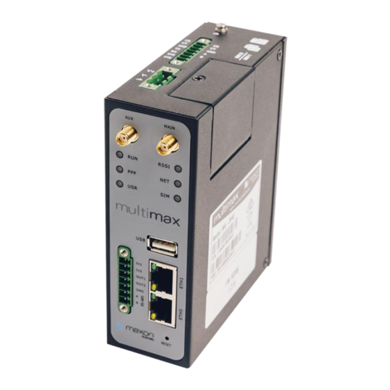
Chapter 1 Product Overview 1.1 Key Features RFI/Maxon Industrial Dual SIM Cellular VPN Router (MA-2040-4G) is a rugged cellular router offering state-of-the-art mobile connectivity for machine to machine (M2M) applications. Multimax+ 4G band 28 modem is a powerful router developed from a new OS, this is a self- developed and Linux-based operating system. -
Page 5: Package Contents
1.2 Package Contents Before installing your Multimax+ Router, verify the kit contents as following. Note: The following pictures are for illustration purposes only, not based on their actual sizes. 1 x Multimax MA-2040 Industrial Dual SIM Cellular VPN Router ... - Page 6 Stubby antenna Magnet antenna RP-SMA WiFi antenna (stubby/magnet optional) Stubby antenna Magnet antenna Wall mounting kit 35 mm DIN rail mounting kit Ethernet cable AC/DC power adapter (12V DC, 1.5 A; EU/US/UK/AU plug optional) Multimax_user manual_v.4.0.4 July.
- Page 7 Multimax_user manual_v.4.0.4 July. 11, 2018 7/139 Confidential...
-
Page 8: Specifications
1.3 Specifications 1.3.1 - Cellular Interface Number of antennas: 2 (MAIN + AUX) Connector: SMA female SIM: 2 (3.0 V & 1.8 V) Standards: GSM/GPRS/EDGE/WCDMA/HSDPA/HSUPA/HSPA+/DC-HSPA+/TD-SCDMA/CDMA (CDMA 1X/EVDO)/FDD LTE/TDD LTE GSM: max DL/UL = 9.6/2.7 Kbps GPRS: max DL/UL = 86 Kbps EDGE: max DL/UL = 236.8 Kbps WCDMA/TD-SCDMA: max DL/UL = 2.8 Mbps/384 Kbps EVDO: max DL/UL = 5.4 Mbps/14.7 Kbps... - Page 9 1 x USB 2.0 host up to 480 Mbps 1 x CLI interface LED indicators - 1 x RUN, 1 x PPP, 1 x USR, 1 x RSSI, 1 x NET, 1 x SIM 1.3.6 - Software Network protocols: PPP, PPPoE, TCP, UDP, DHCP, ICMP, NAT, HTTP, HTTPs, DNS, ARP, NTP, ...
-
Page 10: Dimensions
1.4 Dimensions Multimax_user manual_v.4.0.4 July. 11, 2018 10/139 Confidential... -
Page 11: Chapter 2 Hardware Installation
Chapter 2 Hardware Installation 2.1 PIN Assignment Debug RS-232 Direction To MULTIMAX From Device From MULTIMAX To Device To MULTIMAX From Device From MULTIMAX To Device To MULTIMAX From Device From MULTIMAX To Device Power Positive Negative Multimax_user manual_v.4.0.4 July. 11, 2018 11/139 Confidential... -
Page 12: Led Indicators
DI/DO RS-485 Direction Input 1 To MULTIMAX From Device Input 2 To MULTIMAX From Device Output 1 From MULTIMAX To Device Output 2 From MULTIMAX To Device Data+(A) Half duplex RS- 485 +ve side Data- (B) Half duplex RS- 485 –ve side LED Indicators Multimax_user manual_v.4.0.4 July. - Page 13 Name Color Status Description Green On, fast blinking Router is powered on (250 mSec blink time) (System is initializing) On, blinking Router is operating (500 mSec blink time) Router is powered off Green On, solid Link connection is working Link connection is not working USR-OpenVPN Green On, solid...
-
Page 14: Usb Interface
2.3 USB Interface Function Operation Firmware USB interface is used for batch firmware upgrading, but cannot upgrade be used for sending or receiving data from slave devices which connected to it. You can insert a USB storage device into the router’s USB interface, such as a U disk or a hard disk. -
Page 15: Reset Button
Reset Button Function Operation Reboot Press and hold the RST button for at least 5 seconds under the operating status. Restore to You must power off the modem and power on and wait factory default for 5 seconds after powering up the router, press and hold settings the RST button until all six LEDs start blinking one by one, and release the button to return the router to factory... - Page 16 2.5 Ethernet Ports There are two Ethernet ports, ETH0 and ETH1. Each Ethernet port has two LED indicators. The yellow one is a link indicator, while the green one is a speed indicator. For details about status, see the table below. Indicator Status Description...
-
Page 17: Insert Or Remove Sim Card/Micro Sd Card
2.6 Insert or Remove SIM Card/Micro SD Card Insert or remove the SIM/Micro SD card as shown in the following steps. Insert SIM card/Micro SD card Make sure router is powered off. To remove slot cover, loosen the screw associated with the cover by using a screwdriver and then put the SIM card into the SIM slot/SD card slot. - Page 18 Use the high temperature specific card when the device is working in extreme temperature (temperature exceeding 40 °C), because the regular card for long-time working in harsh environment will tend to disconnect frequently. Do not forget to tighten the cover well to avoid the SIM/SD card being stolen. Do not touch the metal of the card surface as information in the card may be lost or destroyed.
-
Page 19: Attach External Antenna (Sma Type)
2.7 Attach External Antenna (SMA Type) Attach an external SMA antenna to the router’s antenna connector and tighten. Make sure the antenna is within the correct frequency range provided by the ISP and with 50 Ohm impedance. Note: Recommended torque for tightening is 0.35 N.m. The “MAIN”... -
Page 20: Mount The Router
2.8 Mount the Router The router can be placed on a desktop or mounted to a wall or a 35 mm DIN rail. 2.8.1 - Two methods for mounting the router Wall mounting (measured in mm) Use 3 pcs of M3*4 flat head Phillips screws to fix the wall mounting kit to the router, and then use 2 pcs of M3 drywall screws to mount the router associated with the wall mounting kit on the wall. - Page 21 Use 3 pcs of M3*6 flat head Phillips screws to fix the DIN rail to the router, and then hang the DIN rail on the mounting bracket. It is necessary to choose a standard bracket. Note: Recommended torque for mounting is 1.0 N.m, and the maximum allowed is 1.2 N.m. Multimax_user manual_v.4.0.4 July.
-
Page 22: Ground The Router
2.9 Ground the Router Router grounding helps prevent the noise effect due to electromagnetic interference (EMI). Connect the router to the site ground wire by the ground screw before powering on. Note: This product is appropriate to be mounted on a well grounded device surface, such as a metal panel. -
Page 23: Connect The Router To A Computer
2.10 Connect the Router to a Computer Connect one end of an Ethernet cable to the port marked ETH0 or ETH1 and the other end of the cable to your computer. 2.11 Power Supply Multimax Router has reverse polarity protection, but always refers to the figure above to connect the power adapter correctly. -
Page 24: Chapter 3 Initial Configuration
Chapter 3 Initial Configuration The router can be configured through your web browser that including IE 8.0 or above, Chrome and Firefox, etc. A web browser is included as a standard application in the following operating systems: Linux, Mac OS, Windows 98/NT/2000/XP/Me/Vista/7/8/10, etc. It provides an easy and user- friendly interface for configuration. - Page 25 Click Properties in the window of Local Area Connection Status. Choose Internet Protocol Version 4 (TCP/IPv4) and click Properties. Multimax_user manual_v.4.0.4 July. 11, 2018 25/139 Confidential...
- Page 26 Two ways for configuring the IP address of PC Obtain an IP address automatically: Use the following IP address: (Configured a static IP address manually within the same subnet of the router) Click OK to finish the configuration. Multimax_user manual_v.4.0.4 July.
-
Page 27: Factory Default Settings
3.2 Factory Default Settings Before configuring your router, you need to know the following default settings. Item Description Username admin Password admin ETH0 192.168.0.1/255.255.255.0, LAN mode ETH1 192.168.0.1/255.255.255.0, LAN mode DHCP Server Enabled 3.3 Log in the Router To log in to the management page and view the configuration status of your router, please follow the steps below. - Page 28 Multimax_user manual_v.4.0.4 July. 11, 2018 28/139 Confidential...
-
Page 29: Control Panel
3.4 Control Panel After logging in, the home page of the MULTIMAX Router’s web interface is displayed, for example. Using the original password to log in the router, the page will pop up the following tab It is strongly recommended for security purposes that you change the default username and/or password. - Page 30 Cancel Click to cancel the modification on current configuration page. Note: The steps of how to modify configuration are as bellow: Modify in one page; Click under this page; Modify in another page; Click under this page; Complete all modification; Click Multimax_user manual_v.4.0.4 July.
-
Page 31: Status
3.5 - Status This page allows you to view the System Information, Internet Status and LAN Status of your Router. 3.5.1 - System Information System Information Item Description Device Model Show the model name of your device. System Uptime Show the current amount of time the router has been booted. System Time Show the current system time. -
Page 32: Internet Status
3.5.2 - Internet Status Internet Status Item Description Active Link Show the current active link. Uptime Show the current amount of time the link has been connected. IP Address Show the IP address of current link. Gateway Show the default gateway address of the current link. Show the current primary DNS server and secondary server. -
Page 33: Interface
3.6 - Interface 3.6.1 - Interface > Link Manager This section allows you to setup the link connection. General Settings @ Link Manager Item Description Default Primary Link Select from “WWAN1”, “WWAN2”, or “WAN”. WWAN1 WWAN1: Makes SIM1 the primary wireless link ... - Page 34 Revert Interval Specify the number of minutes that elapses before the primary link is checked if a backup link is being used in cold backup mode. 0 means disable checking. Note: Revert interval is available only under the cold backup mode. Emergency Reboot Click the toggle button to enable/disable this option.
- Page 35 The window is displayed as below when disabling the “Automatic APN Selection” option. The window is displayed as below when enabling the “Automatic APN Selection” option. Link Settings (WWAN) Item Description Default WWAN Settings Automatic APN Click the toggle button to enable/disable the “Automatic APN Selection” option.
- Page 36 Password Enter the password for cellular dial-up connection, provided by local ISP. Null Dialup Number Enter the dialup number for cellular dial-up connection, provided by local *99***1# ISP. Authentication Type Select from “Auto”, “PAP” or “CHAP” as the local ISP required. Auto Switch SIM By Data Click the toggle button to enable/disable this option.
- Page 37 Max Ping Tries Set the max ping tries. Switch to another link or take emergency action if the max continuous ping tries reached. Advanced Settings NAT Enable Click the toggle button to enable/disable the Network Address Translation option. Upload Bandwidth Set the upload bandwidth used for QoS, measured in kbps.
- Page 38 Click the right-most button to select the connection status of the current link. Click the row of the link, and it will show the details information of the current link connection under the row. Multimax_user manual_v.4.0.4 July. 11, 2018 38/139 Confidential...
-
Page 39: Interface > Lan
Click the button to clear SIM1 or SIM2 monthly data traffic usage statistics. Data statistics will be displayed only if enable the Data Allowance function in Interface > Link Manager > Link Settings > WWAN Settings > Data Allowance. 3.6.2 - Interface > LAN This section allows you to set the related parameters for LAN port. - Page 40 General Settings Item Description Default Index List position – READ ONLY Interface Show the logical port group this setting applies to. Lan1 is available only if it was selected by one of ETH0~ETH1 in Ethernet > Ports > Port Settings. READ ONLY IP Address Set the IP address assigned to the logical LAN port group.
- Page 41 The window is displayed as below when choosing “Relay” as the mode. Item Description Default DHCP Settings Enable Click the toggle button to enable/disable the DHCP function. Mode Select from “Server” or “Relay”. Server Server: Lease IP address to DHCP clients which have been connected to LAN port ...
- Page 42 WINS Server Define the Windows Internet Naming Service obtained by DHCP Null clients from DHCP sever. Lease Time Set the lease time which the client can use the IP address obtained from DHCP server, measured in seconds. Static lease Bind a lease to correspond an IP address via a MAC address. Null format: mac,ip;mac,ip;..., e.g.
- Page 43 3.6.2.3 - VLAN Trunk Clic k to add a VLAN. The maximum count is 8 . VLAN Trunk Item Description Default Index Position in list – READ ONLY Enable Click the toggle button to enable/disable this VLAN tag. Enable to make router encapsulate and de-encapsulate the VLAN tag.
-
Page 44: Interface > Ethernet
By clicking on a row of the Interface Status area, detailed status information will be display under the row. Please refer to the screenshot below. 3.6.4 - Interface > Ethernet This section allows you to set the related parameters for Ethernet. There are two Ethernet ports on MULTIMAX Router, ETH0 and ETH1. - Page 45 Bridge mode (both ETH ports on same subnet): Routed mode (separate subnets for each ETH port): Routed mode (same as previous, but logical to physical assignment is reversed): Use a wired WAN: Multimax_user manual_v.4.0.4 July. 11, 2018 45/139 Confidential...
- Page 46 Click button of eth0 to configure its parameters. The port assignment can be changed by selecting from the drop down list. Port Settings Item Description Default Index Indicate the ordinal of the list. Port Show the editing port, read only. Port Assignment Choose the Ethernet port’s type, as a WAN port or a LAN port.
-
Page 47: Interface > Cellular
3.6.5 - Interface > Cellular This section allows you to set the related parameters of Cellular. The MULTIMAX Router has two SIM card slots, but do not support two SIM cards online simultaneously due to its single-module design. If insert single SIM card at the first time, SIM1 slot and SIM2 slots are available. The window is displayed as below when choosing “Auto”... - Page 48 Cellular Item Description Default General Settings Cellular Item Description Default Index Indicate the ordinal of the list. SIM Card Set the currently editing SIM card. SIM1 Phone Number Enter the phone number of the SIM card. Null PIN Code Enter a 4-8 characters PIN code used for unlocking the SIM. Null Extra AT Cmd Enter the AT commands used for cellular initialization.
- Page 49 Band Select Type Select from “All” or “Specify”. You may choose certain bands if choosing “Specify”. Advanced Settings Debug Enable Click the toggle button to enable/disable this option. Enable for debugging information output. Verbose Debug Click the toggle button to enable/disable this option. Enable for verbose debugging information output.
- Page 50 Status Item Description Index Indicate the ordinal of the list. Modem Status Shows the status of the radio module. Modem Model Shows the model of the radio module. Current SIM Shows the SIM card that your router is using. Phone Number Shows the phone number of the current SIM.
-
Page 51: Interface > Usb
AT Debug Item Description Default Command Enter the AT command that you want to send to cellular module in this Null text box. Result Show the AT command responded by cellular module in this text box. Null Click the button to send AT command. 3.6.6 - Interface >... -
Page 52: Interface > Di/Do
3.6.7 - Interface > DI/DO This section allows you to set the DI/DO parameters. Digital Input and Digital Output are the specific interfaces for MULTIMAX. The DI interface can be used for triggering alarm, while the DO can be used for controlling the slave device so as to realize real-time monitoring. 3.6.7.1 - DI Click the right-most button of index as shown. - Page 53 Mode Select from “ON-OFF” or “Counter”. ON-OFF ON-OFF: DI interface support ON and OFF mode (high or low level electrical) trigger DI alarm. The mode default to ON, and OFF mode is available only when enabling the inversion feature ON—Under this mode, DI alarm status will be triggered to ON when DI interface open from GND or input a high level electrical (logic 1), on the contrary DI alarm status will be trigged to OFF when DI interface connect to...
- Page 54 The window is displayed as below when choosing “Pulse” as the alarm on action. The window is displayed as below when choosing “Pulse” as the alarm off action. Item Description Default Index Indicate the ordinal of the list. Enable Click the toggle button to enable/disable this DO. Multimax_user manual_v.4.0.4 July.
- Page 55 Alarm On Action Digital Output initiates when there is an alarm. Selected from “High”, “Low” or High “Pulse”. High: a high electrical level output Low: a low electrical level output Pulse: Generates a square wave as specified in the pulse mode parameters when triggered Alarm Off Digital Output initiates when alarm removed.
-
Page 56: Interface > Serial Port
3.6.7.3 - Status This window allows you to view the status of DO and DI interface. It also can clear the counter alarm of DI in here. button to clear DI1 or DI2 monthly usage statistics info for counter Clic k 3.6.8 - Interface >... - Page 57 Serial Port Item Description Default Serial Port Application Settings Index Indicate the ordinal of the list. Port Show the current serial’s name, read only. Enable Click the toggle button to enable/disable this serial port. When the status is OFF, the serial port is not available. Baud Rate Select from “300”, “600”, “1200”, “2400”, “4800”, “9600”, “19200”, “38400”, 115200...
- Page 58 The window is displayed as below when choosing “Transparent” as the application mode and “UDP” as the protocol. The window is displayed as below when choosing “Modbus RTU Gateway” as the application mode and “TCP Client” as the protocol. The window is displayed as below when choosing “Modbus RTU Gateway”...
- Page 59 Server Settings Item Description Default Application Mode Select from “Transparent” or “Modbus RTU Gateway”. Transparent Transparent: Router will transmit the serial data transparently Modbus RTU Gateway: Router will translate the Modbus RTU data to Modbus TCP data and sent out, and vice versa Protocol Select from “TCP Client”, “TCP Server”, “UDP”...
-
Page 60: Network
Local Port @ Modbus Enter the local port of under Modbus mode. Null Click the “Status” column to view the current serial port type. 3.7 – Network 3.7.1 - Network > Route This section allows you to set the static route. Static route is a form of routing that occurs when a router uses a manually-configured routing entry, rather than information from a dynamic routing traffic. -
Page 61: Network > Firewall
Static Route Item Description Default Index Indicate the ordinal of the list. Description Enter a description for this route. Null Destination Enter the IP address of destination host or destination network. Null Netmask Enter the Netmask of destination host or destination network. Null Gateway Define the gateway of the destination. - Page 62 Filtering Item Description Default General Settings Enable Filtering Click the toggle button to enable/disable the filtering option. Default Filtering Policy Select from “Accept” or “Drop”. Cannot be changed when filtering rules Accept table is not empty. Accept: Router will accept all the connecting requests except the hosts which fit the drop filter list ...
- Page 63 Enable Remote Telnet Access Click the toggle button to enable/disable this option. When enabled, the Internet user can access the router remotely via Telnet. Enable Local Telnet Access Click the toggle button to enable/disable this option. When enabled, the LAN user can access the router locally via Telnet. Enable Remote HTTP Access Click the toggle button to enable/disable this option.
- Page 64 Description Enter a description for this filtering rule. Null Source Address Defines if access is allowed from one or a range of IP addresses which are defined Null by Source IP Address, or every IP addresses. Source Port Specify an access originator and enter its source port. Null Source MAC Enter the MAC address of the defined source IP address.
- Page 65 Port Mapping Rules Item Description Default Index Indicate the ordinal of the list. Description Enter a description for this port mapping. Null Remote IP Specify the host or network which can access to the local IP address. Null Empty means unlimited. e.g. 10.10.10.10/255.255.255.255 or 192.168.1.0/24 Internet Port Set the internet port of router which can be accessed by other hosts from...
-
Page 66: Network > Ip Passthrough
Enable DMZ Click the toggle button to enable/disable DMZ. DMZ host is a host on the internal network that has all ports exposed, except those ports otherwise forwarded. Host IP Address Enter the IP address of the DMZ host on your internal network. Null Source IP Address Set the address which can talk to the DMZ host. - Page 67 Enable NAT Traversal Click the toggle button to enable/disable the NAT Traversal function. This option must be enabled when router under NAT environment. Keepalive Set the keepalive time, measured in seconds. The router will send packets to NAT server every keepalive time to avoid record remove from the NAT list.
- Page 68 Mode Select from “Tunnel” and “Transport”. Tunnel Tunnel: Commonly used between gateways, or at an end-station to a gateway, the gateway acting as a proxy for the hosts behind it Transport: Used between end-stations or between an end-station and a gateway, if the gateway is being treated as a host-for example, an encrypted Telnet session from a workstation to a router, in which the router is the actual destination...
- Page 69 The window is displayed as below when choosing “CA” as the authentication type. The window is displayed as below when choosing “xAuth PSK” as the authentication type. The window is displayed as below when choosing “xAuth CA” as the authentication type. Multimax_user manual_v.4.0.4 July.
- Page 70 IKE Settings Item Description Default Negotiation Mode Select from “Main” and “Aggressive” for the IKE negotiation mode in phase 1. Main If the IP address of one end of an IPsec tunnel is obtained dynamically, the IKE negotiation mode must be aggressive. In this case, SAs can be established as long as the username and password are correct.
- Page 71 Local ID Type Select from “Default”, “FQDN” and “User FQDN” for IKE negotiation. Default Default: Uses an IP address as the ID in IKE negotiation FQDN: Uses an FQDN type as the ID in IKE negotiation. If this option is selected, type a name without any at sign (@) for the local security gateway, e.g., test.robustel.com.
- Page 72 SA Settings Item Description Default Encrypt Algorithm Select from “3DES”, “AES128” or “AES256” when you select “ESP” in 3DES “Protocol”. Higher security means more complex implementation and lower speed. DES is enough to meet general requirements. Use 3DES when high confidentiality and security are required.
- Page 73 3.8.1.4 - x509 User can upload the X509 certificates for the IPsec tunnel in this section. x509 Item Description Default X509 Settings Tunnel Name Choose a valid tunnel. Tunnel 1 Certificate Files Click on “Choose File” to locate the certificate file from your computer, and Null then import this file into your router.
-
Page 74: Vpn > Openvpn
3.8.2 VPN > OpenVPN This section allows you to set the OpenVPN and the related parameters. OpenVPN is an open- source software application that implements virtual private network (VPN) techniques for creating secure point-to-point or site-to-site connections in routed or bridged configurations and remote access facilities Router supports point-to-point and point-to-points connections. - Page 75 The window is displayed as below when choosing “Preshared” as the authentication type. The window is displayed as below when choosing “Password” as the authentication type. Multimax_user manual_v.4.0.4 July. 11, 2018 75/139 Confidential...
- Page 76 The window is displayed as below when choosing “X509CA” as the authentication type. Multimax_user manual_v.4.0.4 July. 11, 2018 76/139 Confidential...
- Page 77 The window is displayed as below when choosing “X509CA Password” as the authentication type. General Settings @ OpenVPN Item Description Default Index Indicate the ordinal of the list. Enable Click the toggle button to enable/disable this OpenVPN tunnel. Description Enter a description for this OpenVPN tunnel. Null Mode Select from “P2P”...
- Page 78 Authentication Type Select from “None”, “Preshared”, “Password”, “X509CA” and “X509CA None Password”. Note: “None” and “Preshared” authentication type are only working with P2P mode. Username Enter the username used for “Password” or “X509CA Password” Null authentication type. Password Enter the password used for “Password” or “X509CA Password” Null authentication type.
- Page 79 Advanced Settings @ OpenVPN Item Description Default Enable HMAC Firewall Click the toggle button to enable/disable this option. Add an additional layer of HMAC authentication on top of the TLS control channel to protect against DoS attacks. Enable PKCS#12 Click the toggle button to enable/disable the PKCS#12 certificate. It is an exchange of digital certificate encryption standard, used to describe personal identity information.
-
Page 80: Vpn > Gre
x509 Item Description Default X509 Settings Tunnel Name Choose a valid tunnel. Tunnel 1 Certificate Files Click on “Choose File” to locate the certificate file from your computer, and Null then import this file into your router. The correct file format is displayed as follows: @ca.crt –... - Page 81 3.8.3.1 - GRE Tunnel Settings @ GRE Item Description Default Index Indicate the ordinal of the list. Enable Click the toggle button to enable/disable this GRE tunnel. Maximum of 3 tunnel is allowed Description Enter a description for this GRE tunnel. Null Remote IP Address Set the remote real IP address of the GRE tunnel.
-
Page 82: Vpn > Pptp
3.8.3.2 - Status This section allows you to view the status of GRE tunnel. 3.8.4 VPN > PPTP PPTP (“Point to Point Tunnelling Protocol”) is a VPN technology developed my Microsoft. Due to the popularity of the Windows platform, and seamless integration by Microsoft of PPTP into Windows, it is an extremely popular choice when it needs to work “out of the box”. - Page 83 PPTP server. Start IP Enter the start IP address Enter accordingly which will assign to the PPTP clients End IP Enter The end IP Address Enter accordingly which will assign to the PPTP clients Authentication Select Enter accordingly from”pap”,”chap”,”mschap v1” and ”mschap v2”. Enable NAT Click the toggle button to enable NAT option for PPTP.
-
Page 84: Vpn > L2Tp
Item Description Setting Enable PPTP Server Click the toggle button to enable PPTP VPN server. Username Enter the username which will Enter accordingly be used by L2TP client. Password Enter the password provided Enter accordingly by your PPTP server. Authentication Select Enter accordingly from”pap”,”chap”,”mschap... - Page 85 3.8.5.1 VPN > L2TP > Server Item Description Setting EnableL2TP Server Click the toggle button to enable L2TP VPN server. Username Enter the username which will Enter accordingly be used by L2TP client. Password Enter the password provided Enter accordingly by your L2TP server.
- Page 86 Debug Enable Click the toggle button to enable debugging for L2TP. 3.8.5.2 VPN > L2TP >Client Item Description Setting Index Show the ordinal of the list. Enable Click the toggle button to enable this L2TP VPN tunnel. Description Enter a description for this Null L2TP VPN tunnel.
-
Page 87: Multimax_User Manual_V.4.0.4 July. 11, 2018
Tunnel Secrets Enter the tunnel secret None provided by L2TP server. Port Enter the port number of the 1701 L2TP client. Enable NAT Click the toggle button to Enable enable the NAT feature of L2TP. All Traffic via This Interface After click to enable this Disable feature, all data traffic will be... -
Page 88: Services > Event
Save Position Select the save position from “RAM”, “NVM” or “Console”. Choose “RAM”, the data will be cleared after reboot. Note: It's not recommended that saving syslog to NVM (Non-Volatile Memory) for a long time. Log to Remote Click the toggle button to enable/disable this option. Enable to allow router sending syslog to the remote syslog server. - Page 89 Multimax_user manual_v.4.0.4 July. 11, 2018 89/139 Confidential...
- Page 90 General Settings @ Notification Item Description Default Index Indicate the ordinal of the list. Description Enter a description for this group. Null Sent SMS Click the toggle button to enable/disable this option. When enabled, the router will send notification to the specified phone numbers via SMS if event occurs. Set the related phone number in “3.24 Services >...
- Page 91 The following window you can query various types of events record. Press clear to clear all the data and Click to query Event Details Item Description Default Save Position Select the events’ save position from “RAM” or “NVM”. RAM: Random-access memory ...
-
Page 92: Services > Ntp
3.9.3 Services > NTP This section allows you to set the related NTP (Network Time Protocol) parameters, including Time zone, NTP Client and NTP Server. Item Description Default Timezone Settings Time Zone Click the drop down list to select the time zone you are in. UTC +08:00 Expert Setting Specify the time zone with Daylight Saving Time in TZ environment... -
Page 93: Services > Sms
3.9.4 - Services > SMS This section allows you to set SMS parameters. Router supports SMS management, and user can control and configure their routers by sending SMS. For more details about SMS control, refer to 4.2.2 SMS Remote Control. SMS Management Settings Item Description... -
Page 94: Services > Email
User can test the current SMS service whether it is available in this section. SMS Testing Item Description Default Phone Number Enter the specified phone number which can receive the SMS from router. Null Message Enter the message that router will send it to the specified phone number. Null Result The result of the SMS test will be displayed in the result box. -
Page 95: Services > Ddns
Email Settings Item Description Default Enable Click the toggle button to enable/disable the Email option. Enable TLS/SSL Click the toggle button to enable/disable the TLS/SSL option. Email Settings Item Description Default Outgoing server Enter the SMTP server IP Address or domain name. Null Server port Enter the SMTP server port. -
Page 96: Services > Ssh
DDNS Settings Item Description Default Enable Click the toggle button to enable/disable the DDNS option. Service Provider Select the DDNS service from “DynDNS”, “NO-IP” or “3322”. Note: the DDNS service only can be used after registered by DynDNS Corresponding service provider. Hostname Enter the hostname provided by the DDNS server. - Page 97 SSH Settings Item Description Default Enable Click the toggle button to enable/disable this option. When enabled, you can access the router via SSH. Port Set the port of the SSH access. Disable Password Logins Click the toggle button to enable/disable this option. When enabled, you cannot use username and password to access the router via SSH.
-
Page 98: Services > Web Server
3.9.8 Services > Web Server This section allows you to modify the parameters of Web Server. Basic @ Web Server Item Description Default HTTP Port Enter the HTTP port number you want to change in router’s Web Server. On a Web server, port 80 is the port that the server "listens to"... -
Page 99: Services > Advanced
HTTPS Certificate Click on “Choose File” to locate the certificate file from your computer, and then click “Import” to import this file into your router. 3.9.10 Services > Advanced This section allows you to set the Advanced and parameters. System Settings Item Description Default... -
Page 100: System > Debug
Daily Reboot Time Set the daily reboot time of the router, you should follow the format as HH: MM, Null in 24h time frame, otherwise the data will be invalid. Leave it empty means disable. 3.9.11 System > Debug This section allows you to check and download the syslog details. Multimax_user manual_v.4.0.4 July. - Page 101 Syslog Item Description Default Syslog Details Log Level Select from “Debug”, “Info”, “Notice”, “Warn”, “Error” which from low to high. Debug The lower level will output more syslog in detail. Filtering Enter the filtering message based on the keywords. Use “&” to separate more Null than one filter message, such as “keyword1&keyword2”.
-
Page 102: System > Update
Click the button to refresh the syslog. Syslog Files Syslog Files List It can show at most 5 syslog files in the list, the files’ name range from message0 to message 4. And the newest syslog file will be placed on the top of the list. System Diagnosing Data Generate Click to generate the syslog diagnosing file. -
Page 103: System > Tools
The default might not be installed with all these App. Please contact RFI/Maxon support and request for APP. App Center Item Description Default App Install Click on “Choose File” to locate the App file from your computer, and then click File to import this file into your router. - Page 104 Ping Item Description Default IP address Enter the ping’s destination IP address or destination domain. Null Number of Requests Specify the number of ping requests. Timeout Specify the timeout of ping request. Local IP Specify the local IP from cellular WAN, Ethernet WAN or Ethernet LAN. Null Null stands for selecting local IP address from these three automatically.
- Page 105 Traceroute Item Description Default Trace Address Enter the trace’s destination IP address or destination domain. Null Trace Hops Specify the max trace hops. Router will stop tracing if the trace hops has met max value no matter the destination has been reached or not. Trace Timeout Specify the timeout of Traceroute request.
-
Page 106: System > Profile
Sniffer Item Description Default Interface Choose the interface according to your Ethernet configuration. Host Filter the packet that contain the specify IP address. Null Packets Request Set the packet number that the router can sniffer at a time. 1000 Protocol Select from “All”, “IP”, “TCP”, “UDP”... - Page 107 Profile Item Description Default Import Configuration File Reset Other Settings to Click the toggle button as “ON” to return other parameters to default settings. Default Ignore Invalid Settings Click the toggle button as “OFF” to ignore invalid settings. XML Configuration File Click on to locate the XML configuration file from your computer, and then click...
-
Page 108: System > User Management
Rollback Item Description Default Configuration Rollback Save as a Rollbackable Create a save point manually. Additionally, the system will create a save point every day automatically if configuration changes. Archive Configuration Archive Files Configuration Archive View the related information about configuration archive files, including name, size and modification time. - Page 109 New Username Enter a new username you want to create; valid characters are a-z, A-Z, 0-9, Null @, ., -, #, $, and *. Old Password Enter the old password of your router. The default is “admin”. Null New Password Enter a new password you want to create;...
-
Page 110: Chapter 4 Configuration Examples
Chapter 4 Configuration Examples 4.1 - Interface 4.1.1 Console Port You can use the console port to manage the router via CLI commands, please refer to Chapter 5 Introductions for CLI. Multimax_user manual_v.4.0.4 July. 11, 2018 110/139 Confidential... -
Page 111: Digital Input
4.1.2 Digital Input MULTIMAX supports digital input with dry contact. Please check the connector interface of the router, you can easily find a mark “V-” at one pin of the power connector. Note: Do not connect In1/In2 directly and do not slide the switch to the port marked “GND”... -
Page 112: 112
MULTIMAX supports one RS-232 for serial data communication. Please refer to the connection diagram at the right side. 4.1.5 RS-485 MULTIMAX supports one RS-485 for serial data communication. Please refer to the connection diagram at the right side. 4.2 - Cellular 4.2.1 Cellular Dial-Up This section shows you how to configure the primary and backup SIM card for Cellular Dial-up. - Page 113 Note: All data will be transferred via WWAN1 when choose WWAN1 as the primary link and set backup mode as cold backup. At the same time, WWAN2 is always offline as a backup link. All data transmission will be switched to WWAN2 when the WWAN1 is disconnected. Click the edit button of WWAN1 to set its parameters according to the current ISP.
- Page 114 When finished, click Submit > Save & Apply for the configuration to take effect. The window is displayed below by clicking Interface > Cellular > Advanced Cellular Settings. Click the edit button of SIM1 to set its parameters according to your application request. Multimax_user manual_v.4.0.4 July.
-
Page 115: Sms Remote Control
When finished, click Submit > Save & Apply for the configuration to take effect. 4.2.2 SMS Remote Control The router supports remote control via SMS. You can use following commands to get the status of the router, and set all the parameters. There are three authentication types for SMS control. You can select from “Password”, “Phonenum”... - Page 116 to generate the XML file Go to System > Profile > Export Configuration File, click and click to export the XML file. XML command: <lan > <network max_entry_num="2" > <id > 1</id > <interface > lan0</interface > <ip > 172.16.24.24</ip > <netmask >...
- Page 117 In this command, username is “admin”, password is “admin”, and the function of the command is to get the system status. SMS received: hardware_version = 1.2 firmware_version = "3.0.0" kernel_version = 4.1.0 device_model = MULTIMAX serial_number = 201612221052 uptime = "0 days, 00:40:21" system_time = "Mon Feb 27 09:52:52 2017"...
-
Page 118: Network
4.3 - Network 4.3.1 IPsec VPN The configuration of server and client is as follows. IPsec VPN_Server: Cisco 2811: Multimax_user manual_v.4.0.4 July. 11, 2018 118/139 Confidential... - Page 119 IPsec VPN_Client: The window is displayed as below by clicking VPN > IPsec > Tunnel. Multimax_user manual_v.4.0.4 July. 11, 2018 119/139 Confidential...
- Page 120 Multimax_user manual_v.4.0.4 July. 11, 2018 120/139 Confidential...
-
Page 121: Openvpn
When finished, click Submit > Save & Apply for the configuration to take effect. 4.3.2 OpenVPN OpenVPN supports two modes, including Client and P2P. Here takes P2P as an example. The configuration of two points is as follows. OpenVPN_Server: Generate relevant OpenVPN certificate on the server side firstly, and refer to the following commands to configuration the Server: local 202.96.1.100 mode server port... - Page 122 lzo max-clients 100 persist-key persist-tun status openvpn- status.log verb 3 Note: For more configuration details, please contact your technical support engineer. OpenVPN_Client: Click VPN > OpenVPN > OpenVPN as below. Click to configure the Client01 as below. Multimax_user manual_v.4.0.4 July. 11, 2018 122/139 Confidential...
-
Page 123: Gre Vpn
When finished, click Submit > Save & Apply for the configuration to take effect. 4.3.3 GRE VPN The configuration of two points is as follows. The window is displayed as below by clicking VPN > GRE > GRE. Multimax_user manual_v.4.0.4 July. - Page 124 GRE-1: When finished, click Submit > Save & Apply for the configuration to take effect. GRE-2: Click + configure GRE2 in the remote modem as below. The only difference is the Local Virtual IP address and Remote virtual IP address that is swapped with GRE-1 Multimax_user manual_v.4.0.4 July.
-
Page 125: Chapter 5 Introductions For Cli
When finished, click Submit > Save & Apply for the configuration to take effect. Chapter 5 Introductions for CLI 5.1 What Is CLI The MULTIMAX command-line interface (CLI) is a software interface providing another way to set the parameters of equipment from the SSH or through a telnet network connection. Route login: Router login: admin Password: admin... -
Page 126: How To Configure The Cli
reboot Halt and perform a cold restart route Static route modify dynamically, this setting will not be saved Set system configuration show Show system configuration status Show running system information tftpupdate Update firmware using tftp traceroute Print the route packets trace to network host urlupdate Update firmware using http or ftp Show version of firmware... - Page 127 firmware_version = "3.0.0" kernel_version = 4.1.0 device_model = MULTIMAX serial_number = 201612221052 uptime = "0 days, 00:40:21" system_time = "Mon Feb 27 09:52:52 2017" Example 2: Update firmware via tftp # tftpupdate (space+?) firmware New firmware # tftpupdate firmware (space+?) String Firmware name # tftpupdate firmware MULTIMAX-firmware-sysupgrade-unknown.bin host 192.168.100.99 //enter a new firmware name Downloading...
- Page 128 Network link_manager Link Manager openvpn OpenVPN reboot Automatic Reboot RobustLink RobustLink route Route sms SMS snmp SNMP agent ssh syslog Syslog system System user_management User Management vrrp VRRP web_server Web Server # set link_manager primary_link Primary Link backup_link Backup Link backup_mode Backup Mode emergency_reboot...
- Page 129 username Username password Password dialup_number Dialup Number auth_type Authentication Type aggressive_reset Aggressive Reset switch_by_data_allowance Switch SIM By Data Allowance data_allowance Data Allowance billing_day Billing # set link_manager link 1 wwan switch_by_data_allowance true # set link_manager link 1 wwan data_allowance 100 //open cellular switch_by_data_traffic //setting succeed # set link_manager link 1 wwan billing_day 1...
- Page 130 gateway = "" primary_dns = "" secondary_d ns = "" wins_server = "" lease_time = expert_opti ons = "" debug_enab le = false multi_ip { id = 1 interface = lan0 ip = 172.16.24 netmask = 255.255.0 # set lan network Network Settings multi_ip Multiple IP Address Settings vlan...
- Page 131 # set lan network 1 ip 172.16.24.24 //set IP address for lan //setting succeed # set lan network 1 netmask 255.255.0.0 … # config save_and_apply // save and apply current configuration, make you configuration effect Example 5: CLI for setting Cellular # show cellular all sim id = 1...
- Page 132 band_lte_180 0 = false band_lte_190 0 = false band_lte_210 0 = false band_lte_260 0 = false band_lte_170 0 = false band_lte_700 = false band_tdd_lte _2600 = false band_tdd_lte _1900 = false band_tdd_lte _2300 = false band_tdd_lte _2500 = false sim { id = 2 card = sim2 phone_num...
- Page 133 band_wcdm a_1900 = false band_wcdm a_2100 = false band_lte_80 0 = false band_lte_85 0 = false band_lte_90 0 = false band_lte_18 00 = false band_lte_19 00 = false band_lte_21 00 = false band_lte_26 00 = false band_lte_17 00 = false band_lte_70 0 = false band_tdd_lt...
- Page 134 Settings # set cellular sim(spac e+?) Integer Index (1..2) # set cellular sim 1(space+?) card SIM Card phone_number Phone Number extra_at_cmd Extra AT Cmd network_type Network Type band_select_type Band Select Type band_gsm_850 850 band_gsm_900 GSM 900 band_gsm_1800 GSM 1800 band_gsm_1900 1900 band_wcdma_850 WCDMA 850 band_wcdma_900...
-
Page 135: Commands Reference
band_tdd_lte_2600 TDD LTE 2600 (band 38) band_tdd_lte_1900 TDD LTE 1900 (band 39) band_tdd_lte_2300 TDD LTE 2300 (band 40) band_tdd_lte_2500 TDD LTE 2500 (band 41) # set cellular sim 1 phone_number 18620435279 … # config save_and_apply // save and apply current configuration, make you configuration effect 5.3 Commands Reference Commands Syntax... -
Page 136: Glossary
Glossary Abbr. Description Alternating Current Access Point Name ASCII American Standard Code for Information Interchange Conformité Européene (European Conformity) CHAP Challenge Handshake Authentication Protocol Command Line Interface for batch scripting Circuit Switched Data Clear to Send Decibel Decibel Relative to an Isotropic radiator Direct Current Data Carrier Detect Data Communication Equipment (typically modems) - Page 137 generic route encapsulation Global System for Mobile Communications HSPA High Speed Packet Access identification data IMEI International Mobile Equipment Identity Internet Protocol IPsec Internet Protocol Security kbps kbits per second L2TP Layer 2 Tunneling Protocol local area network Light Emitting Diode Machine to Machine Maximum Minimum...
- Page 138 Request to Send Remote Terminal Unit Receive Direction Software Development Kit subscriber identification module SMA antenna Stubby antenna or Magnet antenna Short Message Service SNMP Simple Network Management Protocol TCP/IP Transmission Control Protocol / Internet Protocol Terminal Equipment, also referred to as DTE Transmit Direction UART Universal Asynchronous Receiver-transmitter...
-
Page 139: Index
Index App Center, 107 LED Indicators, 16 Cellular, 52 Link Manager, 38 Commands Reference, 139 Multiple IP, 48 Console Port, 114 NTP, 97 Contents, 3 OpenVPN, 81, 125 Control Panel, 34 OpenVPN_Client, 127 DDNS, 100 OpenVPN_Server, 126 Debug, 105 PIN Assignment, 15 DI/DO, 59 Port Mapping, 73 Dimensions, 14...
Need help?
Do you have a question about the multimax+ and is the answer not in the manual?
Questions and answers