
Related Manuals for Instron 4400 Series


Summary of Contents for Instron 4400 Series
- Page 1 M10-94400-1 Issue C April 1995 Instron Model 4400 Universal Testing System Operator’s Guide...
- Page 2 Proprietory Rights Notice This document and the information that it contains are the property of Instron Corporation. Rights to duplicate or otherwise copy this document and rights to disclose the document and the information that it contains to others and the right to use the information contained therein may be acquired only by written permission signed by a duly authorized officer of Instron Corporation.
- Page 3 Preliminary Pages Amendment Incorporation Record Person Amendment Brief Description of Incorporating Number Content Numberr Amendment Reverse Strain Mode Switch B3887 Settings...
- Page 4 Preliminary Pages M10-94400-1 Amendment Incorporation Record Person Amendment Brief Description of Incorporating Number Content Numberr Amendment Revision Record Revision ECR No.
- Page 5 Preliminary Pages Materials testing systems are potentially hazardous. Materials testing involves inherent hazards from high forces, rapid motions and stored energy. You must be aware of all moving and operating components which are potentially hazardous, particularly the actuator in a servohydraulic testing system or the moving crosshead in an electromechanical testing system.
- Page 6 Preliminary Pages M10-94400-1 Warning Disconnect the electrical power supply be- fore removing the covers to electrical equip- ment. Disconnect the equipment from the electrical power sup- ply before removing any electrical safety covers or re- placing fuses. Do not reconnect the power source while the covers are removed.
- Page 7 Preliminary Pages Warning Shut off the supply of compressed gas and discharge residual gas pressure before dis- connecting any compressed gas coupling Do not release gas connections without first disconnect- ing the gas supply and discharging any residual pressure to zero. Use protective shields or screens if any pos- sibility exists of a hazard from the failure of a specimen, assembly or structure under...
- Page 8 Preliminary Pages M10-94400-1 Warning Wear protective clothing when handling equipment at extremes of temperature. Materials testing is often carried out at non-ambient tem- peratures using ovens, furnaces or cryogenic chambers. Extreme temperature means an operating temperature ex- ceeding 60 °C (140 °F) or below 0 °C (32 °F). You must use protective clothing, such as gloves, when handling equipment at these temperatures.
- Page 9 Preliminary Pages Warning Do not place a testing system offline from computer control without first ensuring that no actuator or crosshead movement will oc- cur upon transfer to manual control. The actuator or crosshead will immediately respond to manual control settings when the system is placed off- line from computer control.
-
Page 10: Table Of Contents
Preliminary Pages M10-94400-1 Table of Contents Chapter Page Introduction Outline .................1-1 Introduction ..............1-2 About this Manual ..........1-3 Product Support ..........1-3 General Characteristics ..........1-4 Console Components ..........1-7 Front Panel ..............1-8 Main Panel Section ..........1-8 Display Panel Section .........1-10 Limits Panel Section ...........1-10 Crosshead Control Section .........1-11 Internal Status Indicators ........1-12 Recorders ............1-12... - Page 11 Preliminary Pages Table of Contents (continued) Chapter Page Installation (continued) Console Connections...........3-3 Mounting the Console .........3-3 Attaching the Console........3-3 Mounting the Console Bracket ......3-4 Connector Panel ..........3-5 Installing Cables ..........3-7 Cabling for Optional Equipment ......3-9 Cables............3-9 Analog Output Connector ......3-9 Opening the Console ...........3-11 Function Of Controls Outline .................4-1...
- Page 12 Preliminary Pages M10-94400-1 Table of Contents (continued) Chapter Page Function Of Controls (continued) Self Test Result - Failures ........4-25 Self Test Result Display ........4-25 Version Number ............4-31 Selecting Operating Units ..........4-32 Switching Units ...........4-32 Operating Units for Self Identified Load Cells and Load Frames..........4-33 Operating Units for Non-Self Identified Load Cells and Load Frames........4-34...
- Page 13 Preliminary Pages Table of Contents (continued) Chapter Page System Operation (continued) Manual Calibration of Non-Self Identifying Load Cells ............5-13 Load Weighing System Balance ......5-15 Calibration And Balance Errors......5-16 Strain Calibration ............5-18 Overview .............5-18 Strain Operating Mode........5-18 Strain Gauge Extensometers......5-20 Electrical Calibration of Self Identifying Strain Gauge Extensometers ........5-22 Manual Calibration of Strain Gauge Extensometers ...........5-22...
- Page 14 Preliminary Pages M10-94400-1 Table of Contents (continued) Chapter Page System Options Overview..............6-1 Introduction ..............6-2 Strip Chart Recorder............6-3 Description ............6-3 Specifications............6-4 Power Requirements ........6-6 Installation............6-7 Operation ............6-8 Pen Scaling...........6-8 Pen Calibration ..........6-9 X-Y Recorder ...............6-12 Description ............6-12 Specifications............6-13 Installation............6-15 Power Requirements ........6-15 Signal Input Connection........6-15 Operation ............6-16 Initial Setup ...........6-16...
- Page 15 Preliminary Pages Table of Contents (continued) Chapter Page System Options (continued) AC/DC Strain Conditioner..........6-30 Specifications............6-31 Installation............6-31 Operation ............6-32 Preset Points ...............6-34 Description ............6-34 Operation ............6-35 Energy .................6-37 Description ............6-37 Operation ............6-37 Cycle Counter ..............6-39 Pip Control ..............6-41 Air Kit Option ...............6-44 Overview .............6-44 Description ............6-44 Operation ............6-45...
- Page 16 Preliminary Pages M10-94400-1 Table of Contents (continued) Chapter Page Test Check List Maintenance Overview..............8-1 Introduction ..............8-2 General ...............8-2 Special Maintenance Considerations....8-2 Preventive Maintenance ..........8-3 Cleaning - Control Console.........8-3 Error Messages ............8-4 Overview .............8-4 Displaying Error Messages .........8-4 Rear Panel Indicators ..........8-10 Rear Panel Indicators .........8-10 General ............8-10 Power Supply Condition Indicators ....8-11...
- Page 17 Preliminary Pages Table of Contents (continued) Chapter Page Appendix A Test Planning (continued) Establishing Gauge Length..........A-7 Selection Of Testing Speed .........A-8 Strain Rate..............A-9 Area Compensation .............A-10 Description ............A-10 Determining Stress Range........A-11 Limitations Due To Load Cell Capacity ....A-12 Chart Magnification............A-14 Appendix B Glossary xvii...
- Page 18 Preliminary Pages M10-94400-1 List of Illustrations Figure Page 1-1. Functional Block Diagram ..........1-5 1-2. Control Console Front Panel ........1-9 3-1. Console Rear Panel Connectors .........3-6 3-2. Rear Panel Cable Arrangement........3-8 3-3. Access to Interior of Console........3-12 4-1. Main Panel..............4-3 4-2. Display Section ............4-12 4-3.
- Page 19 Preliminary Pages List of Tables TablePage 3-1. Series 4400 Console Option Cables......3-9 3-2 Analog Output Connector Pin Assignments ....3-10 4-1. Main Panel Functions ..........4-3 4-2. Display Section Functions ...........4-12 4-3. Limits Section Functions..........4-14 4-4. Variables and Functions in Nonvolatile Memory................4-17 4-5.
- Page 20 Preliminary Pages M10-94400-1 List of Tables (continued) Table Page 6-10. Example Pip Delay Values vs Test Speeds ....6-43 6-11. Air Kit Functions ............6-46 8-1. Sections of the Control Console ........8-5 8-2. Error Messages ............8-7 8-3. LED Error Codes for IEEE-488 Section Tests .....8-14 8-4.
- Page 21 Preliminary Pages...
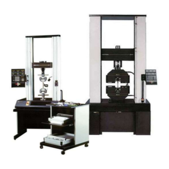
- Page 22 Preliminary Pages M10-94400-1 Frontispiece. Series 4400 Universal Testing System xxii...
- Page 23 • Console Internal Functions ... . Page 1-14 The Instron Series 4400 Universal Testing Instruments are electromechanical systems employing the latest printed cir- cuit board technology to provide a small, light and efficient testing system.
-
Page 24: Introduction
Introduction M10-94400-1 Introduction The Instron Series 4400 Universal Testing Instrument is a materials testing instrument designed to test the strength of a wide variety of materials. The system is made up of a load frame, in which a specimen of the... -
Page 25: About This Manual
If you encounter any problems with using or maintain- ing your testing instrument, or if you want to order ac- cessories or parts, you can obtain answers to your questions or place orders by calling Instron Service, us- ing the list below: In the United States:... -
Page 26: General Characteristics
General Characteristics M10-94400-1 General Characteristics The Series 4400 control system is made up of two major subsystems: a crosshead drive and control system, that applies tensile or compressive loading to a specimen; and a highly sensitive load weighing system, that meas- ures the loading of a specimen. -
Page 27: Functional Block Diagram
General Characteristics Figure 1-1. Functional Block Diagram... - Page 28 General Characteristics M10-94400-1 A CPU-controlled sensor conditioner in the load weigh- ing system allows calibration and balance procedures to be performed automatically, after you initiate them at the front panel. The sensor conditioner provides both an unranged analog and an automatically ranged digital load signal output suitable for several types of optional readout devices.
-
Page 29: Console Components
Console Components Console Components The Series 4400 Control Console contains a single printed circuit board on which are mounted all of the electrical components, including the front panel switches and displays, and rear panel connectors. The console printed circuit board is the interface for all connections to the console. -
Page 30: Front Panel
Front Panel M10-94400-1 Front Panel The Front Panel (Figure 1-2) is divided into four major sections. The Main section contains a numeric keypad for data entry of system setup parameters, an LCD dis- play for the numeric input, pushbuttons for such func- tions as crosshead speed selection, and gauge length setting, among others. -
Page 31: Control Console Front Panel
Front Panel Figure 1-2. Control Console Front Panel... -
Page 32: Display Panel Section
Front Panel M10-94400-1 Display Panel Section The Display Panel section contains three 4-digit LCD displays and control keys to allow load, extension, and strain to be tracked during a test, and the peak and break values of these parameters to be observed. All values are computed and saved at the end of each test and may be viewed as needed during and after the test. -
Page 33: Crosshead Control Section
Front Panel The action assigned to a limit can be: STOP - stop crosshead at current position. RETURN - return crosshead to gauge length. CYCLE - change direction of crosshead motion at the limit. OFF - no action An indicator lamp lights at the active limit and at the re- lated crosshead action key. -
Page 34: Internal Status Indicators
Front Panel M10-94400-1 Internal Status Indicators A series of Light Emitting Diode (LED) indicators are mounted on the circuit board inside the console, but are visible through a window cutout in the rear panel. These indicators report the condition of power supply voltages, the pass/fail condition of some CPU functions during the Self-Diagnostic Test, and on the activity of CPU circuits during normal operation. - Page 35 Front Panel Single Pen Strip Chart Recorder Cat. No. 2310-904 Double Pen Strip Chart Recorder Cat. No. 2310-905 1-13...
-
Page 36: Console Internal Functions
Console Internal Functions M10-94400-1 Console Internal Functions In addition to the operator interface and cabling inter- face functions described previously, the console circuit board provides a number of internal functions to com- plete the testing system. These functions include a Cen- tral Processing Unit (CPU), a Crosshead Control function, a Load Sensor Conditioner, a Strain Sensor Conditioner, and an IEEE-488 Interface function. -
Page 37: Strain Sensor Conditioner
Console Internal Functions This function provides interfacing between the load transducer (load cell) and the console. Functions that this section supplies are excitation to a load cell, process- ing of its output signal, and providing calibrated analog and digital load weighing information to the console and readout devices. - Page 38 Console Internal Functions M10-94400-1 1-16...
-
Page 39: Specifications
Chapter 2 Specifications • Introduction ......Page 2-2 • Specifications..... . . Page 2-3 This chapter lists physical and electrical specifications for the Series 4400 Control Console. -
Page 40: Specifications Introduction
The generalized specifications in this chapter will help you to determine whether your system will meet your in- dividual testing requirements. If you have any questions about specifications, your regional Instron Sales Engi- neer will be happy to assist you. -
Page 41: Specifications
Specifications Specifications Components Standard: Main Panel Display Panel Limits Panel Load Sensor Conditioner RS-232 Interface Options: Strain Sensor Conditioner IEEE-488 Interface Strip Chart Recorder X-Y Recorder Printer Power Requirements +5 Vd.c. +15 Vd.c. -15 Vd.c. (All voltages supplied from Load Frame, must be free of spikes, surges, or sags exceeding 10% of the average voltage) Operating Performance... - Page 42 Specifications M10-94400-1 Strain Measurement Accuracy ±0.05% of full scale or ±0.5% of reading (whichever is greater) ±1 count on the strain display Strain measurement system meets or surpasses the following standards: ASTM E83, BS3846, ISO 9513, EN1002-4 Environmental Requirements Operating temperature: +10 to +38 °C (+50 to +100°F) (other ranges available on request) Storage temperature:...
- Page 43 Specifications Materials Enclosure: Structural foam Keyboard: Cleanable mylar surface with silicon rubber switches. Dimensions Height: 406.4 mm (16 in.) Width: 280 mm (11 in.) Depth: 58.2 mm (2.3 in.) Weight 2.7 kg (6 lb) approx.
- Page 44 Specifications M10-94400-1...
-
Page 45: Installation (Continued)
Chapter 3 Installation Outline • General Considerations ....Page 3-2 • Console Connections ....Page 3-3 •... -
Page 46: General Considerations
General Considerations M10-94400-1 General Considerations Installation of a basic Series 4400 testing instrument is described in the load frame manual for the system. This chapter describes how to access the interior of the con- sole and install cabling for optional devices. The basic cables, Load and Frame, are installed at the factory. -
Page 47: Console Connections
Console Connections Console Connections Mounting the Console The Series 4400 Console is attached to a console mounting bracket that is, in turn, mounted on one of the load frame columns, either directly in grooves in the column cover (ta- ble models) or on an extension of the column cover (floor models). -
Page 48: Mounting The Console Bracket
Console Connections M10-94400-1 (b) Insert a socket head cap screw in each of the four mounting holes and hand tighten. (c) With all screws in place, tighten the screws evenly until all are secure. (d) Attach the sliding bracket to the pivot bracket using the pins provided. -
Page 49: Connector Panel
All of the connectors are standard D-shell connectors. TEST - Connector used by Instron Service person- nel for testing the IEEE-488 interface. An IEEE-488 Service Test printed circuit board, which is available only to service personnel, is required to run this test. -
Page 50: Console Rear Panel Connectors
Console Connections M10-94400-1 Figure 3-1. Console Rear Panel Connectors... -
Page 51: Installing Cables
Console Connections POWER - the d.c. connector for control console main power. The input voltage to the console is sup- plied from the load frame, where a d.c. power sup- ply is located that provides d.c. power for the entire system. -
Page 52: Rear Panel Cable Arrangement
Console Connections M10-94400-1 (c) When all cables have been connected, dress the cables into the cable clips provided on the console mounting bracket, as shown in Figure 3-2. This will ensure that the cables will not catch on the load frame, grips, or testing fixtures while the crosshead is moving. -
Page 53: Cabling For Optional Equipment
Console Connections Cabling for Optional Equipment Cables For Series 4400 systems, a recorder, printer and com- puter connect directly to the rear panel of the console, us- ing the cables provided with these options (see Table 3-1). The cables for load and strain measuring devices plug into connectors on the devices themselves, as de- scribed in the system load frame manual. -
Page 54: Analog Output Connector Pin Assignments
Console Connections M10-94400-1 Table 3-2. Analog Output Connector Pin Assignments Pin Number Signal Metal Shell Chassis Ground Load Strain No Connection Analog Ground Analog Ground Digital Ground No Connection The pinout appears as follows, looking at the connector: 5 4 3 2 1 9 8 7 6 The Load and Strain output pin signals are ±10 volts, relative to Analog Ground. -
Page 55: Opening The Console
Opening the Console Opening the Console Under normal conditions, it should not be necessary to open the console. There are no user-serviceable compo- nents or adjustments inside the console case, but if it should become necessary to check for loose internal con- nections or wiring, or to install an option board, you can open the console as follows (also see Figure 3-3): Warning... -
Page 56: Access To Interior Of Console
Opening the Console M10-94400-1 Figure 3-3. Access to Interior of Console (f) Reassemble the console in reverse order of the steps to disassemble. Be sure to replace all screws. (g) Remount the console on its mounting bracket. (h) Reinstall cabling removed in step (a). Be sure to tighten all connector screws to prevent connectors from falling loose during operation. -
Page 57: Function Of Controls
Chapter 4 Function Of Controls Outline • Preliminary Considerations ... . Page 4-2 • Function of Controls ....Page 4-3 •... -
Page 58: Preliminary Considerations
Preliminary Considerations M10-94400-1 Preliminary Considerations The purpose of this chapter is to provide details of the operational features of the Series 4400 Control Console, so the application of each device and its purpose in the calibration and operation of the system will be under- stood. -
Page 59: Function Of Controls
Function Of Controls Function Of Controls Main Panel Figure 4-1. Main Panel Table 4-1. Main Panel Functions CONTROL or FUNCTION INDICATOR Numeric Keypad (a)Numeric Keys, 0 through 9, allow entry of: 1. Value of calibration signal for manually calibra- transducers. 2. - Page 60 Function Of Controls M10-94400-1 Table 4-1. Main Panel Functions (continued) CONTROL or FUNCTION INDICATOR Numeric Keypad (b) +/- key defines the values of load, extension, (continued) and strain as + for tension testing and - for com- pression testing. This key is also used when enter- ing the electronic limits.
- Page 61 Function Of Controls Table 4-1. Main Panel Functions (continued) CONTROL or FUNCTION INDICATOR AREA Enables an area compensation circuit which divides both displayed load value and output voltage to a recorder by a set value between 1.000 and 9.999. When this key is pressed, the SET LED lights and an area value can be ≠...
- Page 62 Function Of Controls M10-94400-1 Table 4-1. Main Panel Functions (continued) CONTROL or FUNCTION INDICATOR LOAD BAL Sets a load cell balance, or zero, during a calibration procedure or when balancing out the tare of grips and fixtures before starting a test. The LOAD BAL key LED is lit during a balance operation or if a load calibration relay is closed.
- Page 63 Function Of Controls Table 4-1. Main Panel Functions (continued) CONTROL or FUNCTION INDICATOR LOAD Fault indicator that lights when a load overrange (102% or greater of load cell maximum capacity) occurs. The crosshead stops and the indicator flashes until the overload is cleared by pressing the UP or DOWN key or a JOG key on the load frame, whichever direction decreases the measured load.
- Page 64 Function Of Controls M10-94400-1 Table 4-1. Main Panel Functions (continued) CONTROL or FUNCTION INDICATOR POWER Fault indicator that lights if a momentary power failure occurs. Momentarily shutting down system power clears this condition. PRINT Obtain a printout of the current test at any time, or a printout of the last test when no test is running.
- Page 65 Function Of Controls Table 4-1. Main Panel Functions (continued) CONTROL or FUNCTION INDICATOR (c) Diagnostic Monitor - Press S1, then 2 and ENTER on keypad. This sequence initiates the diagnostic troubleshooting routine which is part of the Resi- dent Test Program for the Series 4400 console (refer to Resident Test Program for details and exiting procedure).
- Page 66 Function Of Controls M10-94400-1 Table 4-1. Main Panel Functions (continued) CONTROL or FUNCTION INDICATOR (f) Set Preset Point Values - if the values of the Preset (continued) Points (PPT1, PPT2) are to be other than the de- fault values as shown in Table 4-5, then the follow- ing key sequences are used to enter new values (where PPT1 and PPT2 are indicated, enter the actual numerical value on the keypad of the...
- Page 67 Function Of Controls Table 4-1. Main Panel Functions (continued) CONTROL or FUNCTION INDICATOR (j) Air Kit Option – provides automatic grip control (continued) for pneumatic grips. The key sequence [S1][7][+/–] enables or diables grip control, and the Main Panel Display shows “SL 7 when enabled and ”SL–7" when disabled.
-
Page 68: Display Section
Function Of Controls M10-94400-1 Display Section Figure 4-2. Display Section Table 4-2. Display Section Functions CONTROL or FUNCTION INDICATOR LOAD A 4-digit display which indicates + and - values of load DISPLAY between .0001 and 9999. The display shows “——” when the load cell is uncalibrated;... -
Page 69: Display Section Functions
Function Of Controls Table 4-2. Display Section Functions (continued) PEAK Sets the displays to show load, extension and strain values that occur at the peak load during a test. These values are held on the display at the end of a test. When a test begins, the displays show current tracking values until a “peak”... -
Page 70: Limits Section
Function Of Controls M10-94400-1 Limits Section Figure 4-3. Limits Section Table 4-3. Limits Section Functions CONTROL or FUNCTION INDICATOR LOAD MAX/MIN Electronic limits which permit an action to be EXTENSION MAX/ independently assigned to the maximum and minimum values of load, extension or strain, or to detect break. An STRAIN MAX/MIN LED to the left of each key lights when the key is pressed. -
Page 71: Limits Section Functions
Function Of Controls Table 4-3. Limits Section Functions (continued) STATUS A rectangular STATUS LED is located to the right of the LEDs BREAK key and one each between the LOAD, EXTENSION, and STRAIN MAX/MIN limit keys. When a limit or break detection is selected to cause a crosshead action (except OFF), the related STATUS LED lights. -
Page 72: Data Storage
Data Storage M10-94400-1 Data Storage Nonvolatile Memory The data storage capability of a Series 4400 control con- sole includes a nonvolatile memory; that is, data re- mains in storage, even though main power is removed, due to battery backup. The retention period of the non- volatile memory, with a fully charged battery, is up to ninety days without refreshing. -
Page 73: Variables And Functions In Nonvolatile Memory
Data Storage Table 4-4. Variables and Functions in Nonvolatile Memory VARIABLE or FUNCTION DEFAULT VALUE or CONDITION Crosshead Speed Area 1.000 Calibration (Both Zero and Scale) Uncalibrated Testing Area BELOW XHEAD Peak/Track/Break TRACK Load Limit Action 0/OFF (Both MAX and MIN Extension Limit Action 0/OFF (Both MAX and MIN) - Page 74 Data Storage M10-94400-1 Table 4-4. Variables and Functions in Nonvolatile Memory (continued) VARIABLE or FUNCTION DEFAULT VALUE or CONDITION Preset Points Independent Strain (active channel) Variable Energy Independent Variable Strain (active channel) Autoprint Option Disabled (Reenter S1 - - - sequence) Preset Points Printout Suppressed (Reenter S1 - - - sequence)
- Page 75 Data Storage The tracked variables are never stored, but are updated every 50 milliseconds during a test. The Gauge Length will also default to present crosshead position whenever main power is removed. 4-19...
-
Page 76: Resident Test Program Overview
Resident Test Program Overview M10-94400-1 Resident Test Program Overview The Series 4400 control consoles contain a Resident Test Program which is a feature designed to provide sup- port for several levels of automatic testing of the con- sole. This test program includes a Self Test Routine, a Cyclic Self Test and a Diagnostic Monitor. - Page 77 Resident Test Program Overview If all circuit boards pass the self test, the coded number disappears and normal operation can begin. If not, the re- sulting number on the Main Panel Display remains and only a continuation of the Resident Test Procedure can be run.
- Page 78 Resident Test Program Overview M10-94400-1 lows a detailed list of errors to be scanned which can di- rectly indicate component failures. Note The Diagnostic Monitor is for use by qualified maintenance personnel, but limited use is de- scribed in Chapter 9 for the readout of error messages.
-
Page 79: Self Test Routine
Self Test Routine Self Test Routine This section provides information about the automatic self test feature of the Series 4400 console. The Self Test Routine consists of two parts as described in this section. It is initiated when power is applied to the control console, and cannot be bypassed. -
Page 80: Self Test - Part 2
Self Test Routine M10-94400-1 Self Test - Part 2 After the first part of the Self Test Routine, all LEDs turn off and the LCDs become blank. This condition persists for 2 to 5 seconds. During this second part, you should again scan the panels and check that all LEDs go off and LCDs are blank. -
Page 81: Self Test Result - Failures
Self Test Routine Self Test Result - Failures When failures have been detected during the Self Test, the test result shows on the Main Panel Display. How- ever, normal operation cannot be started and pressing ENTER on the keypad has no effect. Record the test re- sult, as it provides important service information. -
Page 82: Control Console Sections
Self Test Routine M10-94400-1 Figure 4-4. Console Section Numbers Assigned to Main Panel Display for Self Test Result Each half of each digit in the display represents a func- tional section in the console. The top halves are assigned to optional sections and the bottom halves to basic sec- tions (except Nos. -
Page 83: Coding Of Display Results For Self Test Result
Self Test Routine The method in which each half digit of the display is coded to represent a functional section condition is by deleting a segment of the digit for a “good” or “bad” in- dication, or by displaying all segments if a section is not used. - Page 84 Self Test Routine M10-94400-1 Example No 1. All sections in use and all good. Example No 2. IEEE Board not in use and Crosshead Control Section bad. 4-28...
-
Page 85: Characters Possible In Self Test Result For Each Digit Of Main Panel Display
Self Test Routine Table 4-6. Characters Possible in Self Test Result for Each Digit of Main Panel Display 1st Digit 2nd Digit 3rd Digit 4th Digit *NOT *NOT POSSIBLE POSSIBLE *NOT *NOT POSSIBLE POSSIBLE *NOT *NOT POSSIBLE POSSIBLE *NOT POSSIBLE *NOT *NOT POSSIBLE... - Page 86 Self Test Routine M10-94400-1 4-30...
-
Page 87: Version Number
Version Number Version Number The system firmware, which is the resident program that is stored in non-volatile memory, has been updated on sev- eral occasions over the life of the Model 4400 Testing Sys- tem. In order for some of the option functions and features described in Chapter 6 to work properly, the firmware must have a certain version date. -
Page 88: Selecting Operating Units
Selecting Operating Units M10-94400-1 Selecting Operating Units Switching Units The operating units (English, metric, S.I.) in use in a Se- ries 4400 system is controlled by the position of the units selection switch, marked “mm/IN/SI” located on the rear panel of the console. The switch is a rocker type;... -
Page 89: Operating Units For Self Identified Load Cells And Load Frames
Selecting Operating Units (c) Enter the “warm start” sequence: Press S1, then press [1] and [ENTER] on the keypad. After you switch units and perform one of the above pro- cedures, the Main Panel display will show “LOSS”, indi- cating that nonvolatile memory is reset to the default state and stored test data is lost. -
Page 90: Operating Units For Non-Self Identified Load Cells And Load Frames
Selecting Operating Units M10-94400-1 The units shown in Table 4-7 provide the scaling for the Display Panel and recorder options, and are the units that appear on a printout of test results. Note When Area Compensation is not equal to 1.000, the load signal to the LOAD display and recorder are scaled by 1/AREA (normalized). -
Page 91: Area
Selecting Operating Units If the load frame is not self identified, then the scaling of the extension parameter for the EXTENSION display, recorder and printer options and the speed parameter de- pend upon the units in use (inches or millimeters); you must record this separately. - Page 92 Selecting Operating Units M10-94400-1 Examples of Energy units printout: English units LB*EX in./A Metric units kGf*EX mm/A S.I. units N*EX mm/A 4-36...
-
Page 93: System Operation
Chapter 5 System Operation Outline • Operating Considerations ... . . Page 5-2 • Pretest Procedures ....Page 5-3 •... -
Page 94: Operating Considerations
Operating Considerations M10-94400-1 Operating Considerations A typical test worksheet, which enables you to preplan a test program, is included in Chapter 7. With the blank spaces filled in where applicable, the worksheet serves as a permanent record for future reference. This record is important even for repetitive testing routines during which parameters may remain unchanged for a period of time. -
Page 95: Pretest Procedures
Pretest Procedures Pretest Procedures The Test Setup Procedures in the following list help you to prepare your Series 4400 testing system to run basic tension and compression tests. Follow the procedures se- quentially, since many of them require that other proce- dures be performed first. -
Page 96: Turn Instrument On: Warm-Up
Turn Instrument On: Warm-up M10-94400-1 Turn Instrument On: Warm-up To turn on power to the Series 4400 instrument, set the main power switch on the load frame to ON. The com- plete testing system receives power, but any external ac- cessories, such as a recorder or a printer, must be turned on separately. -
Page 97: Self Test Routine At Power Up
Self Test Routine At Power Up Self Test Routine At Power Up The following sequence occurs during the automatic self test of the Series 4400 system when main power is ap- plied. Monitor this routine closely, as it provides assur- ance of the reliability of the system before proceeding with test programs. - Page 98 Self Test Routine At Power Up M10-94400-1 (b) After a successful Self Test, observe the following actions (depending upon options installed): (1) On the Main Panel: a. The STOP switch is lit. b. The display is blank, or it shows “LOSS” if the operating units or the strain mode has been changed before turning power on.
-
Page 99: System Reset At Initial Power Up
System Reset At Initial Power Up System Reset At Initial Power Up When you initially power up your Series 4400 system, we recommended that you enter a System Reset se- quence at the end of the Self Test Routine. This ensures that system data storage is at the default state (Table 4-5). -
Page 100: Load Calibration
Load Calibration M10-94400-1 Load Calibration Overview The Load Measurement function of the Series 4400 System consists of a precision load cell transducer, mounted on the load frame crosshead, and a Load Sensor Conditioner, lo- cated on a section of the console printed circuit card. The calibration procedure precisely calibrates the load weighing system for the load cell in use. -
Page 101: Electrical Calibration Of Self Identifying Load Cells
BAL LED is lit, and the calibration and balance func- tions are locked out while a test is running. Note Instron recommends that you check calibration at least once a day during continuous operation of your testing system. Electrical Calibration of Self Identifying Load Cells... -
Page 102: Manual Calibration Of Self Identifying Load Cells
Load Calibration M10-94400-1 Manual Calibration of Self Identifying Load Cells Note When manually (deadweight) calibrating a load cell, use a precision weight that is trace- able to a particular class as defined by the National Bureau of Standards. To calibrate the load weighing system manually with a self identifying load cell installed: (a) Do one of the following: (1) If you are using a tension load cell, install a pin or... - Page 103 Load Calibration EXAMPLE: If a 2518 Series cell is installed and is to be used over its full capacity in metric units (50 kg), then the calibration weight should be no less than 20 kg. (e) Press the LOAD CAL key. The Main Panel Display shows the maximum capacity of the cell and the LOAD CAL LED lights (f) On the numeric keypad, key in the actual value of the...
-
Page 104: Electrical Calibration Of Non-Self Identifying Load Cells
The calibration point for electrically calibrated load cells is the maximum capacity of the next to the highest range of the cell. For the Instron low capacity tension load cells, this number would be as shown in Table 5-1 (for example, 200 for the type 2512-101 cell). -
Page 105: Manual Calibration Of Non-Self Identifying Load Cells
Load Calibration Table 5-1. Low Capacity Load Cells Calibration Data TENSION CELL MAXIMUM CALIBRATION CATALOG NO. CAPACITY POINT 2512-136 50 g 20 g 2512-101 500 g 200 g 2512-122 (h) After about 6 seconds, the LOAD CAL LED goes out and the display goes blank indicating that calibra- tion is completed. - Page 106 Load Calibration M10-94400-1 (1) If you are using a tension load cell, install a pin or other device in the coupling of the cell for apply- ing a calibration weight. (2) If you are using a compression load cell, set the cell on its cap on the base of the load frame.
-
Page 107: Load Weighing System Balance
Load Calibration EXAMPLE: If a 2518-204 cell is installed and is to be used over its full capacity in English units (200 lb), then the calibra- tion weight should be no less than 80 lb. (h) On the numeric keypad, key in the actual value of the calibration weight in the system of units in use (S.I., English or metric). -
Page 108: Calibration And Balance Errors
Load Calibration M10-94400-1 To balance the load weighing system: (a) Press the LOAD BAL key. The LOAD BAL LED lights. (b) Press ENTER. After about 3 seconds, the LOAD BAL LED goes out and the balance function is com- pleted. (see next Section if LOAD BAL LED flashes.) Calibration And Balance Errors Your Series 4400 system reports when a problem exists... -
Page 109: Transducer Calibration/Balance Errors
Load Calibration Table 5-2. Transducer Calibration/Balance Errors CALIBRATION OR PROBABLE CAUSE SOLUTION BALANCE ERROR CAL LED flashes after a 1. Transducer is not con- 1. Check all cable con- self identifying transducer is nected. nections. calibrated automatically 2. Transducer is defective. 2. -
Page 110: Strain Calibration
Strain Calibration M10-94400-1 Strain Calibration Overview Strain measurement on the Series 4400 system makes use of an optional Strain Sensor Conditioner board. This Strain channel can accept a wide variety of strain transducers, including strain gauge extensometers, LVDT extensometers, Crack Opening Displacement gauges, and several types of specialized extensometers for specific applications. - Page 111 Strain Calibration panel of the console (see Figure 8-1). The bottom, number 3 switch is marked STRAIN UNITS. To change the position of the Strain Mode switch, push on one side of the switch with a pointed tool, such as a ball point pen.
-
Page 112: Strain Gauge Extensometers
(Load, Extension, and Strain). Strain Gauge Extensometers Instron manufactures a host of different types of exten- someters and other strain measuring devices, most of which can be used with the Series 4400 Testing System. - Page 113 Series 4400 system. Note An extensometer calibrator with a micrometer adjustment, such as the Instron High Magnifi- cation Extensometer Calibrator with a 25 mm (or 1 in.) range, is required for the manual calibration procedures.
-
Page 114: Electrical Calibration Of Self Identifying Strain Gauge Extensometers
Strain Calibration M10-94400-1 Electrical Calibration of Self Identifying Strain Gauge Extensometers Note When electrically calibrating a 2630 Series self-identifying strain gauge extensometer, the balance operation is performed automatically. To electrically calibrate a 2630 Series self-identifying strain gauge extensometer: (a) Clamp the extensometer onto the specimen at gauge length, as described in the manual supplied with the extensometer. - Page 115 Strain Calibration (c) Clamp the extensometer onto the calibrator spindles at gauge length, as described in the manual supplied with the extensometer. Allow up to 15 minutes for the extensometer to stabilize after applying excitation. (d) Press the STRAIN BAL key. The STRAIN BAL LED lights.
- Page 116 Strain Calibration M10-94400-1 full scale. For example: If using an extensometer with a 1-inch gauge length and a 10% maximum strain, adjust calibrator to 0.100 inches. (2) To calibrate the extensometer over a range of in- terest (most accurate method), adjust the calibra- tor to the maximum displacement value required.
-
Page 117: Extensometers - Operating Notes
Strain Calibration (l) Press ENTER. After 3 seconds, the STRAIN BAL LED goes out and the balance function is completed. Strain Gauge Extensometers - Operating Notes The strain measuring accuracy of a Series 4400 system is 0.5% of the strain reading, ±1 count, on the display or the analog output to recorder (±... -
Page 118: Display Panel
Display Panel M10-94400-1 Display Panel Description The Display Panel at the top of the control console has three 4-digit LCD displays which allow the current value of load, extension, and strain to be tracked for ob- servation during a test. The tracking value on each dis- play is not stored at the end of the test. - Page 119 Display Panel (b) Press the PEAK key to set the displays to show load, extension and strain values that occur at the peak load during a test. This can be done at any time, either be- fore, during, or at the end of a test when the values are stored.
-
Page 120: Establish Gauge Length
Establish Gauge Length M10-94400-1 Establish Gauge Length Gauge length is the distance between the contact points of the upper and lower grips on the specimen at the start of a test, and establishes the initial length of the speci- men. The choice of a suitable gauge length depends upon the material under test (see Appendix A, Introduc- tion to Testing). - Page 121 Establish Gauge Length (b) Press the G.L. RESET key to reset the EXTENSION display to zero. (c) Drive the crosshead up with the JOG key until the re- quired spacing is displayed (in inches or millime- ters), and again press the G.L. RESET key to enter the new gauge length into system memory.
-
Page 122: Electronic Limits
Electronic Limits M10-94400-1 Electronic Limits You should set the electronic limits and assign a cross- head action to them before starting a test. Enter limits values using the keypad and view them on the Main Panel Display. An indicator lights at the active limit and at the corre- sponding crosshead action key. -
Page 123: Operation
Electronic Limits (4) When Area Compensation is in use, the gain of the load signal actuating the Load Limits is divided by the normalized mantissa (base number) of the area value (see Area Compensation on page 5-38). Hence, when Area Compensation is not equal to 1.000, the Load Limits should be set based on the normalized value of stress. - Page 124 Electronic Limits M10-94400-1 limit value (maximum or minimum load or strain) must also be negative. Press the +/- key on the keypad to obtain the correct sign when setting a limit. 2. If the sign (+ or -) of the output signal of the load cell (or strain transducer) in use is nega- tive (-) with increasing load (or strain), the Series 4400 system considers the most nega-...
- Page 125 Electronic Limits key LEDs will light. The crosshead action may be changed by pressing another action key. Note If the crosshead action is to CYCLE between LOAD limits during a compression test and the load cell in use has a positive (+) output signal for an increase in load (2511-200 series), set TESTING AREA to ABOVE XHEAD.
-
Page 126: Set Crosshead Travel Limit Stops
Set Crosshead Travel Limit Stops M10-94400-1 Set Crosshead Travel Limit Stops The crosshead travel limit stops are a safety feature that you should set after establishing gauge length and before starting a test. Refer to the load frame manual for your sys- tem for the location of these devices. -
Page 127: Set Crosshead Speed
Set Crosshead Speed Set Crosshead Speed The testing (crosshead) speed you select depends upon the type of material being tested. Some examples of typi- cal speeds are given in Appendix A, Introduction to Test- ing. Usually, a testing rate is specified as one of the following: •... - Page 128 Set Crosshead Speed M10-94400-1 (b) Enter the required speed on the keypad (up to four digits and a decimal point). The displayed number flashes, indicating that it has not been entered into the system. (c) Press ENTER. The number stops flashing. Note You can change crosshead speed at any time during a test by entering the above sequence.
-
Page 129: Crosshead Jog Control
Crosshead Jog Control Crosshead Jog Control A Crosshead Jog Control unit is available for moving the crosshead up and down in small increments or at slow speed while loading specimens or installing grips and fixtures. The Jog Control unit is a small, hand-held box on the end of a cable, containing a rocker switch. -
Page 130: Area Compensation
Area Compensation M10-94400-1 Area Compensation Area Compensation is a feature of the Series 4400 sys- tem that allows the load signal to be calibrated in terms of stress (Load/Area). Thus, specimens of similar mate- rial but different cross-sectional area can be tested and a relationship established between the applied force and the specimen size. - Page 131 Area Compensation EXAMPLE: Specimen cross-sectional area: A = 0.156 in = 1.56 x 10 Enter -01 as the exponent of the area value. The load signal output to the LOAD display and to a re- corder is divided by the mantissa of the area value only. Therefore, stress (Load/Area) as indicated by these two devices is normalized in relation to actual stress.
- Page 132 Area Compensation M10-94400-1 value or the value of a previously set area compensa- tion). (b) Enter the mantissa (base number) of the desired area compensation on the keypad. This must be a number between 1.000 and 9.999, which is the normalized value of the specimen cross-sectional area.
- Page 133 Area Compensation entered exponent. 2. I f the maximum and minimum load limits are used, they should be reset in accordance with the increased or decreased load channel sensi- tivity due to area compensation (the normalized value only, not the exponent) (see Operating Note (4) on page 5-31).
-
Page 134: Install Specimen
Install Specimen M10-94400-1 Install Specimen Install a test specimen in the grips for tension testing, or on the compression platen or other fixture for compres- sion testing. The gauge length has been set at this point, so do not move the crosshead. If the specimen does not fit, either trim it or change the gauge length. -
Page 135: Set Testing Area
Set Testing Area Set Testing Area It is important that you set the TESTING AREA func- tion on the Main Panel properly so that the automatic overload detection circuit will stop a test if the load cell is overranged. If pneumatic grips are being used with an optional Air Kit, or cycling is to be done using the Lim- its Section of the panel, it is essential to set the TEST- ING AREA properly. - Page 136 Choose another extensometer of the proper polarity or call an Instron Regional Sales and Service Office for additional extensometers. To change TESTING AREA, enable it by initially press- ing S1.
-
Page 137: Run A Test
Run a Test Run a Test The output of a test with only a load cell installed is a load signal of 0 to ±10 Vd.c. This signal can be moni- tored on the Display Section of the panel, and recorded if an optional Recorder or Printer is installed. - Page 138 Run a Test M10-94400-1 5-46...
-
Page 139: System Options
Chapter 6 System Options Outline • Introduction ......Page 6-2 • Strip Chart Recorder ....Page 6-3 •... -
Page 140: Introduction
Introduction M10-94400-1 Introduction The options described in this chapter are either external accessories that can be added to the system (Recorders, Printer) or are built into the system (Energy option, Pre- set Points option, Air Kit option, Pip Control option, etc.). -
Page 141: Strip Chart Recorder
Strip Chart Recorder Strip Chart Recorder Description The optional Instron Strip Chart Recorder produces a plot of an input signal, usually load or strain, against time. The chart itself, driven by an internally-timed step- ping motor, moves past a recording pen, which, in turn, is driven by the input signal. -
Page 142: Specifications
Strip Chart Recorder M10-94400-1 from Instron. The recorder can be operated in either Eng- lish or metric units, switch-selectable on the rear panel of the recorder. Specifications The following are the operating specifications for the Strip Chart Recorder: Measurement Ranges: 1, 2, 5, 10, 20, 50, 100, 200, 500... - Page 143 Strip Chart Recorder DC Volts, V Ranges: 2 MΩ AC Volts, mv Ranges: 20 KΩ, in series with 1 µf AC Volts, V Ranges: 2 MΩ Permitted Source Impedance mv Ranges: 20 kΩ V Ranges: 5 kΩ Temperature Drift of Zero Line approx.
-
Page 144: Power Requirements
Strip Chart Recorder M10-94400-1 Table 6-1. Strip Chart Recorder Supplies Part Number Description Quantity 3750-135 Fan Fold Paper, 10/box metric units 3750-137 Fan Fold Paper, 10/box U.S. Customary units 3750-136 Roll Paper, metric 10 rolls/box units 2750-138 Roll Paper, U.S. 10 rolls/box Customary units 3740-147... -
Page 145: Installation
Strip Chart Recorder Table 6-2. Recorder Line Voltage Selection Set a.c. input connector If Line Voltage is: 120 ±10 Vac 100 ±10 Vac 220 ±10 Vac 240 ±10 Vac proper value for the line voltage in use (see the Recorder manual). -
Page 146: Operation
Strip Chart Recorder M10-94400-1 Plug the recorder input cable (A570-26), provided with the unit, into the ANALOG OUT connector on the rear of the console. Connect the other end of the cable into the 9-pin D-shell connector on the right-rear corner un- derneath the recorder. -
Page 147: Pen Calibration
Strip Chart Recorder (b) Use the VAR control to set the pen exactly on the left edge of the chart. This will be more precise if the chart is moving, since the pen will draw a line in- stead of making a dot. (c) Select a scale factor on the RANGE switch which gives full scale deflection of the pen. -
Page 148: Calibration Signal For Load Cells
Strip Chart Recorder M10-94400-1 (1) To close the load cell relay, press the LOAD CAL key on the Series 4400 front panel, then press 0 and ENTER. The LOAD CAL and LOAD BAL LEDs are both lit when this relay is closed. Table 6-3. - Page 149 Strip Chart Recorder SI units, as shown in Table 6-3. In Metric units, the calibration voltage is 50.9% of full scale, while in U.S. Customary units, this voltage is 56.2% of full scale (51.9% for a 600 kN Load Cell). EXAMPLE Assume a 5 kN (1000 lb, 500 kg) load cell is installed and English units are in use.
-
Page 150: X-Y Recorder
M10-94400-1 X-Y Recorder Description The optional Instron X-Y Recorder is another type of re- corder that plots two variables against each other. Unlike the Strip Chart Recorder, the X-Y Recorder’s chart is sta- tionary, and plots are made with one or two moving pens. -
Page 151: Specifications
X-Y Recorder Specifications The following is a complete set of specifications for the X-Y Recorder: Calibrated Ranges: 0.5, 1, 2, 5, 10, 20 mv/cm 0.05, 0.1, 0.2, 0.5, 1, 2 V/cm Variable Range Ex- up to 250% (sensitivity increase) pansion: Over entire writing width ±100% Zero Line Shift: Input Impedance:... -
Page 152: Recorder Supplies
X-Y Recorder M10-94400-1 Paper Hold-down: Electrostatic Max Writing Speed X-Axis: 70 cm/sec Y-Axis: 100 cm/sec Cutoff Frequency @ -3dB X-Axis: 1.4 Hz (280 mm) Y-Axis: 3 Hz (200 mm) Power Consumption Operating: 25 VA Standby: 10 VA 100, 110, 220, 240 Va.c. ±10% Input Voltage: Dimensions (WxHxD) 379.5x150x372 mm Weight:... -
Page 153: Installation
X-Y Recorder Installation Power Requirements The X-Y Recorder is set at the factory to accept a main power input of 120 ±10 Va.c., single phase. A 3-wire power cable for this voltage is included. If the power source to be used is not 120 ±10 Va.c., the power input switch on the underside of the recorder can be set for other voltages in the range of 100 to 240 Va.c. -
Page 154: Operation
X-Y Recorder M10-94400-1 Note The recorder must be electrically grounded to operate properly. Operation The Series 4400 system does not provide any control functions for the recorder; it merely supplies analog data signals which are scaled and plotted by the recorder. The following sections give the procedures for using the re- corder with the Series 4400 Testing System. -
Page 155: Model 4400 X-Y Recorder Panel
X-Y Recorder Calib. Main Control Module X Axis Controls Y Axis Controls Select. Time Mode X Servo Mode Moves Pen on Pen moves on X axis as a Positions pen on the Y axis Select switch X axis from left to function of an analog signal from a These basic controls must in response to the load force... -
Page 157: Calibration
X-Y Recorder (d) Press the Pen Lift switch to the Up (pen up) position. (e) Place a sheet of chart paper on the platen of the Re- corder with the lower edge of the sheet against the bottom paper stop, and its left edge against the left paper stop. - Page 158 X-Y Recorder M10-94400-1 The X-Axis and Y-Axis Modules are essentially identi- cal and both are calibrated in the same way. Use the fol- lowing procedure for both types of Modules: (a) Set the polarity switch (+/–) to your required polarity as follows: X-Axis: + (button UP) = increasing signal toward top of chart...
- Page 159 X-Y Recorder (f) If a self-identified transducer is installed, closing the transducer calibration relay will apply a precision transducer signal to the recorder (refer to the Note and Example below). (1) To close the load cell or extensometer relay, press the LOAD CAL or STRAIN CAL key on the Model 4400 front panel, then press 0 and ENTER.
-
Page 160: Time Base Operation
X-Y Recorder M10-94400-1 (g) If a non-self identified transducer is installed, hang a precision weight, within the range of the load cell, from the cell, or displace the extensometer with the calibrator, and observe the pen deflection. (h) Adjust the CAL variable control on the recorder to set the pen to exactly the value of the precision weight or extensometer deflection. -
Page 161: Normal Operation
X-Y Recorder (b) Choose a chart speed that correlates with the Model 4400 testing speed. Look up that speed in Table 6-3 and set the Recorder Time Base Selector switch to the corresponding speed. (c) Press the RESET button on the Time Base Module. The pen will lift and return to the left edge of the chart. -
Page 162: Printer
The printer is set up for and supplied with 9 x 11 inch fan-fold paper. Additional pads of paper are available from Instron. Installation To use the printer with the Series 4400 System, plug the signal cable provided with the unit into the RS-232 con- nector on the rear panel of the console. -
Page 163: Operation
Printer Operation An operating instructions manual is supplied with the printer. This section provides the additional procedures required to use the unit with the Series 4400 System. (a) To obtain a printout at any time, press the PRINT key on the Main Panel. (b) To obtain a printout automatically at the end of a test, enter the key sequence [S1] [6] [+/–] on the key- pad. -
Page 164: Printer Units
Printer M10-94400-1 Line 4 – Preset Point 1 data. If Preset Points are sup- pressed, line 4 is omitted. Line 5 – Preset Point 2 data. If Preset Points are sup- pressed, line 5 is omitted. Line 6 – Preset Point 3 data. If Preset Points are sup- pressed, line 6 is omitted. -
Page 165: Energy Units Printout
Printer Besides the system operating units, the printed units for Energy and Preset Points depend upon the independent variable (extension or strain), and, if strain is the inde- pendent variable, the extensometer type (self-identified or non-self identified). The units that appear in the printout of the Energy field and for Total Energy are shown in Table 6-7. -
Page 166: Printout With Strain As Independent Variable
Printer M10-94400-1 Table 6-8. Printout with Strain as Independent Variable LB/A MILS LB*SI PEAK = -1.616E02 5.469 23.54 -7.69E00 BREAK = -9.745E01 5.482 23.45 -7.69E00 PPT1 = -2.953E-01 10.00 -2.870E00 PPT2 = -2.953E-01 20.00 5.827E00 SPEED = 5.000 IN/MIN AREA = 2.00E-01 TOTAL ENERGY = -7.737E00 LB*SI MILS/A... - Page 167 Printer Notes 6-29...
-
Page 168: Ac/Dc Strain Conditioner
The AC/DC Strain Conditioner Option is an add-on printed circuit board that allows the use of extensome- ters, such as the Instron Video Extensometer, the High Resolution Digital (HRD) Extensometer, and other strain transducers that use d.c. excitation and signal proc- essing. -
Page 169: Specifications
AC/DC Strain Conditioner Specifications AC/DC Strain Conditioner Catalog Number 2210-865 Differential ±11V maximum Input 10 Kohm max impedance ±7 to ±11 Volts, full scale Calibration sum of signal and imbalance must not exceed ±11 V input maximum Input Selection Automatic by jumper in adapter (DC vs AC) cable Installation... -
Page 170: Operation
AC/DC Strain Conditioner M10-94400-1 not necessary to remove the mounting bracket from the rear cover. (f) Orient the new Strain Conditioner printed circuit card so that the four mounting holes in the card align with four plastic posts protruding from the back of the main printed circuit board. - Page 171 AC/DC Strain Conditioner contains jumpers that tell the Model 4400 that a DC Extensometer is attached. • When using a DC Extensometer, the Strain channel is calibrated in the same manner as a normal Strain channel. See the calibration instructions in Chapter 5 of this manual.
-
Page 172: Preset Points
Preset Points M10-94400-1 Preset Points Description The Preset Points option allows you to specify the val- ues of up to three independent variables at three preset points for recording the values of three dependent vari- ables. Preset Points data is accessible through the RS- 232 connector on the rear panel, but there is no provision for displaying it on the front panel. -
Page 173: Operation
Preset Points Operation The procedure required to use the Preset Points Option is to set the independent variable, set the preset point val- ues, and then enable the option to get a printout at the end of a test. The default condition of the independent variable is the active strain channel or extension if the strain option is no installed. - Page 174 Preset Points M10-94400-1 [S1] [42] PPT2 [ENTER] [S1] [43] PPT3 [ENTER] Where PPT1, PPT2, and PPT3 are indicated, enter the actual numerical value of the independent variable; Ex- tension in inches or millimeters; or Strain in either per- cent, mils, or millimeters. To obtain a printout of load and energy (refer to the next section, “Energy”) at the preset points, enter the key se- quence:...
-
Page 175: Energy
Energy Energy Description The Energy option allows you to obtain, at the end of a test, the total energy under the load curve, the values at Peak and Break, and the values at three preset points. En- ergy is defined as the integral of composite load (analog load divided by analog area) and extension or strain. - Page 176 Energy M10-94400-1 To obtain a printout of energy values at the end of a test, enter the key sequence: [S1] [3] [+/–] The Main Panel Display will show either: SL–3 to suppress printout, or SL 3 to enable printout Toggle the [+/–] key until the required display appears. 6-38...
-
Page 177: Cycle Counter
Cycle Counter Cycle Counter A Cycle Counter function is another feature of the Model 4400 Console that counts and displays crosshead reversals of direction. Each time the crosshead changes direction as a result of a limit action, a key press at the console, or an IEEE Command, the cycle count is incre- mented by 0.5 counts. - Page 178 Cycle Counter M10-94400-1 the setup display. Simply press [S1] [+/–] again to return to the count display. The cycle limit action can be set on the front panel by pressing [S1] [8] [1] . When the S1 and 8 are pressed, the setup display will show “S1 8".
-
Page 179: Pip Control
Control device options include a Remote Manual Pushbutton (In- stron Catalog No. 2310-516), an Instron XL Elastomeric Extensometer, or an Instron Incremental Extensometer. The pip height is factory set at approximately one chart division on a 250 mm (10 inch) wide chart. - Page 180 Pip Control M10-94400-1 IEEE Bus. To enter a delay from the front panel, use the key sequence: [S1] [8] [2] When the S1 and 8 are pressed, the setup display will show “S1 8". When the 2 is pressed, the current delay value will be shown.
-
Page 181: Example Pip Delay Values Vs Test Speeds
Pip Control Table 6-10. Example Pip Delay Values vs Test Speeds Test Speed (in/min) Delay (seconds) above 20 0.100 2.000 20.00 below 0.0002 9999 Test Speed (mm/min) Delay (seconds) above 1000 0.500 1.000 50.00 500.0 0.005 9999 6-43... -
Page 182: Air Kit Option
Air Kit Option M10-94400-1 Air Kit Option Overview The Air Kit Option is a set of hardware and firmware to provide control and operation of pneumatic grips in sev- eral manual and semi-automatic modes during testing sessions. It consists of a Pneumatic Control Box, a Foot- switch assembly, and interconnecting electrical cables and air hoses. -
Page 183: Operation
Air Kit Option noid activated, and open when the solenoid valve is deac- tivated and air pressure released. The Pneumatic Control Box is mounted on one of the columns of the load frame. This unit contains the sole- noid valves and a small printed circuit board. It is the hub of the pneumatic and electrical connections;... -
Page 184: Manual Operation
Air Kit Option M10-94400-1 Table 6-11. Air Kit Functions Setting Default Grip Control Enable/Disable Disabled Pretension Enable/Disable Disabled Excess Tension Enable/Disable Disabled Automatic Start Enable/Disable Disabled Automatic Release Enable/Disable Disabled Pretension Level Excess Tension Level The Pretension, Excess Tension, Automatic Start, and Automatic Release functions enable or disable their re- spective features. -
Page 185: Grip Control Function Operation
Air Kit Option taneously when pressed. There is no other interaction with the Model 4400 System in full manual mode. Grip Control Function Operation To enable the Grip Control function: (a) Press [S1] [7]. Read the current state of the Grip Con- trol function from the Main Panel Display. -
Page 186: Automatic Start Operation
Air Kit Option M10-94400-1 level, both grips open. Both grips can be opened at any time by pressing the OPEN foot pedal. Once both grips are open, a new sequence can begin. To enable or disable the Pretension function, do the fol- lowing: (a) Press [S1] [7] [1]. -
Page 187: Automatic Release Operation
Air Kit Option This is useful with or without Pretension operation. If Pretension is disabled, the test will start when the foot pedal is pressed the second time to close the lower grip. With Pretension enabled, the test will start when the Pre- tension Level is reached and the lower grip closes (auto- matically), provided the load stays within the Pretension Hysteresis and Excess Tension ranges. -
Page 188: Set Pretension Level
Air Kit Option M10-94400-1 (c) Use the [+/–] key to toggle between the enabled and disabled state. Set Pretension Level To set the Pretension Level, do the following: (a) Press [S1] [7] [5]. (b) After the [5] key has been pressed, read the current Pretension Level on the Main Panel Display. -
Page 189: Continuous Pretension Testing
Air Kit Option Continuous Pretension Testing To set up for continuous Pretension testing, do the fol- lowing: (a) Set a Pretension Level and enable Pretension. (b) Set an Excess Tension Level and enable Excess Ten- sion (this step is optional). (c) Enable Automatic Start. - Page 190 Air Kit Option M10-94400-1 6-52...
-
Page 191: Test Check List
Chapter 7 Test Check List This Materials Test Check List is included as an aid for you to preplan a test program. It can also serve as a re- cord for completed tests. The format of the list is only a suggestion. - Page 192 Test Check List M10-94400-1 TEST EQUIP- Load Frame Type Test Area Specimen Grips Type Load Cell Type Extensometer (Strain ) Printer Computer Recorder Other Accessories, Special Fixtures, Equipment TEST EQUIPMENT Test Reference No. System Operating Units S. I., Metric, English Load Cell Calibration Self/Non-Self ID Auto/Manual...
- Page 193 Test Check List Energy Preset Points Enable/ Disable Enable/ Disable Energy Integration Variable Preset Points Independent Variable Preset Point Values Preset Point 2 Preset Point 1 Extensometer Calibration Auto/Manual Self/Non-Self ID Strain Operating Mode Percent (%) or Displacement Strip Chart Recorder % Range Ratio Chart Speed Time/Proportional...
- Page 194 Test Check List M10-94400-1 Display Panel Load, Extension, Strain Monitoring (Track, Peak, Break) Limits Assignments Variable Max Limit Min Limit Crosshead Action Load Extension Strain Break Detection Crosshead Action Cycle Action Increase Load (Up/Down) REMARKS...
-
Page 195: Maintenance
Chapter 8 Maintenance Overview • Introduction ......Page 8-2 • Preventive Maintenance....Page 8-3 •... -
Page 196: Introduction
The control console contains a single printed circuit board, on which are located all the features and func- tions of the system. Instron maintains a stock of factory- tested replacement boards that can be used to replace a defective board in your system. There are no complex, time-consuming troubleshooting procedures, and no highly technical replacement of defective parts. -
Page 197: Preventive Maintenance
Preventive Maintenance Preventive Maintenance Cleaning - Control Console Periodically clean the exterior surfaces of the Control Console with a soft, lint-free cloth. To remove grime, dampen the cloth with water and a mild detergent. Do not use strong cleaners or solvents on any part of the unit, and do not allow cleaning water to leak into the in- terior of the console. -
Page 198: Error Messages
By using this feature of the monitor, you can communicate to an Instron service representative the ex- act nature of a failure, thus expediting repair procedures. Displaying Error Messages If the Self Test Routine detects a failure, the result appears on the Main Panel Display. -
Page 199: Sections Of The Control Console
Error Messages When “HELP” is on the display, press [ENTER] to change the display to “E”. This indicates that the Error type command is in effect. The “E” type commands are numbered 0 through 9, ex- cept “4” and “7”, which are not used. You must enter one of these numbers on the keypad, followed by [EN- TER] to execute an “E”... - Page 200 Error Messages M10-94400-1 (a) When the “E” command displays, press [0] [EN- TER]. The display shows “E 1. - -” if no error exists in Section 1. If an error exists, a message displays that relates to a failed test as shown in Table 8-2. (b) Record any error message, then repeat pressing [EN- TER] to display messages for any additional errors in Section 1.
- Page 201 Error Messages Table 8-2. Error Messages CIRCUIT MESSAGE FAILED TEST BOARD IEEE-488 E1.00 I/O Port Test E1.01 Memory Initialization State Bit Test E1.02 Two Port Ram Test E1.03 Normal Mode State Bit Test E1.04 Compatibility Code Test E2.01 PROM 0 Test - Checksum E2.02 PROM 0 Test - Start Address E2.03...
- Page 202 Error Messages M10-94400-1 Table 8-2. Error Messages (continued) CIRCUIT MESSAGE FAILED TEST BOARD Load Sensor Con- E5.00 I/O Port 1 Test E5.01 I/O Port 0 Test ditioner E5.02 A/D Run/Hold/Status Test E5.03 A/D 0 Volts Test E5.04 A/D 5 Volt Test E5.05 Load Section ID Test Strain Sensor Con-...
- Page 203 Error Messages (b) Record any error message, then repeat pressing [EN- TER] to display messages for any additional errors on Section 3. (c) After all error messages display for Section 3, and you press [ENTER] the display shows “E.3 - -” for the end of the list.
-
Page 204: Rear Panel Indicators
Rear Panel Indicators M10-94400-1 Rear Panel Indicators Rear Panel Indicators General The printed circuit board used in the Series 4400 console is divided into functional sections. These functions in- clude Main Panel, Display Panel, Limits Panel, Load Sensor Conditioner, and the like, and they operate more or less independently of one another. -
Page 205: Power Supply Condition Indicators
Rear Panel Indicators Power Supply Condition Indicators Three LEDs indicate the condition of the three console power supply voltages from the load frame: +5 Vd.c., +15 Vd.c. and -15 Vd.c. Each LED is lit when its respec- tive power supply voltage is present, and it is off if that power supply has failed. -
Page 206: Red Activity Leds
Rear Panel Indicators M10-94400-1 STRAIN BOARD (When Installed) IEEE-488 MAIN CONSOLE BOARD (When BOARD Installed) Figure 8-1. Rear Panel Indicators Red Activity LEDs Each section with a microprocessor has a red ACTIV- ITY LED; these include the CPU, the IEEE-488 Inter- face section, and the Front Panel section. -
Page 207: Red Latch Indicator Leds
Rear Panel Indicators LED just after power on or system reset indicates a RAM problem. Red Latch Indicator LEDs The latch indicators include the red CPU A RAM LED and the red Crosshead Control FAULT LED. These LEDs are never on except when a latch has been trig- gered and a system reset (main power turned off and then on) is required. -
Page 208: Ieee-488 Interface Indicators
Rear Panel Indicators M10-94400-1 the TIMER status indicator on the Main Panel also lights when this occurs. IEEE-488 Interface Indicators The IEEE-488 section has additional indicators that are exclusive for its particular functions; these are the red ERROR, LISTENING, and TALKING LEDs. During the Self Test Routine after system power is ap- plied, the IEEE section undergoes a series of tests. -
Page 209: Summary Of Operating Sequence For Rear Panel Indicators
Rear Panel Indicators Summary of Operating Sequence for Rear Panel Indicators The moment after main power is applied, or a system re- set occurs, the green TEST LEDs for each circuit section light. At the end of this initial period, the self test of the processor on the CPU section (No. -
Page 210: Fault Indications
Fault Indications M10-94400-1 Fault Indications The fault indicators on the Main Panel light under cer- tain conditions occurring during system operation. The chart below lists the probable cause of these conditions and the action to be taken. Table 8-4. Fault Indications FAULT INDICATOR CAUSE CORRECTIVE ACTION... -
Page 211: Appendix A Test Planning
Appendix A Test Planning The purpose of this appendix is to provide the basic re- quirements that are essential in planning a materials test- ing procedure. These include the applications of the testing instrument, determining load requirements, grip- ping techniques, setting gauge length, choosing a testing speed and the use of area compensation. -
Page 212: Applications
Applications M10-94400-1 Applications The test capabilities of a Series 4400 instrument range from simple tension or compression testing with a record- ing of specimen loading versus time, to more advanced techniques, including modulus tests, relaxation-recovery, and cyclic evaluations involving detailed calculations and data analysis. - Page 213 Applications specified strain. Use specimen dimensioning and peak readouts to enable printouts of maximum force or stress values. Other typical tests include: ASTM-D695 and D1621 for compression; D732 for shear strength; D1004 for tear resistance; and D1894 for friction. WIRE, FOIL, SHEET METAL - determine the tensile strength of solid wire, electrical cables, and thin sheet metal components.
-
Page 214: Load Requirements
Load Requirements M10-94400-1 Load Requirements The selection of a load cell is the first step in preparing for a tension or compression test. If the approximate ten- sile (or compressive) strength of the specimen is known, the choice of load cell is simplified. If the tensile strength of the material is not known, refer to a Proper- ties of Materials handbook to obtain a close figure. -
Page 215: Selection Of Grips
Selection Of Grips Selection Of Grips The selection of grips depends upon the material, geome- try and strength of the test specimen; but the tensile strength of the test specimen should be a primary consid- eration. If, for example, a material has a tensile strength of 500 lbf, then pneumatic grips should not be used, as these grips are designed for loads not exceeding 200 lbf. - Page 216 Selection Of Grips M10-94400-1 Table A-1. Gripping Techniques SPECIMEN SPECIMEN MAX. BREAK TYPES OF GRIPS MATERIAL GEOMETRY LOAD (LB) AND FACES Paper 25 mm (1 in.) Screw-action or wide Pneumatic (25 x 50 mm flat faces) Plastic Films 25 mm (1 in.) Same as above.
-
Page 217: Establishing Gauge Length
Establishing Gauge Length Establishing Gauge Length The gauge length used for a tensile test refers to the original length of the specimen or the initial distance be- tween the grips. Whereas for a compression test, it refers to the original height of the specimen, assuming the an- vil and compression table are both initially in contact with the specimen. -
Page 218: Selection Of Testing Speed
Selection Of Testing Speed M10-94400-1 Selection Of Testing Speed The selection of a testing (or crosshead) speed depends upon the material being tested and the type of test. Mate- rials that are very stiff, such as metals and rigid plastics, should be tested at a slow speed. -
Page 219: Strain Rate
Strain Rate Strain Rate For certain materials, the specimen strain rate is speci- fied rather than a testing speed. But once the gauge length (G.L.) has been established, the testing speed can be calculated from the strain rate. Testing Speed = Strain Rate x G.L. EXAMPLE: Specimen: Plastic film Gauge length: 10 in. -
Page 220: Area Compensation
Area Compensation M10-94400-1 Area Compensation Description The use of area compensation when testing specimens of different cross-sectional area allows the load signal to be calibrated in terms of stress, or similar units relating force and specimen size. Stress is defined as the load on a specimen divided by the original cross-sectional area of the specimen. -
Page 221: Determining Stress Range
Area Compensation a number normalized between 1.000 and 9.999. As a re- sult, the digital load signal to the LOAD display and the analog load signal to a recorder are both normalized with respect to stress. This allows calibration of the re- corder scale in terms of stress (normalized), with the full scale value easily changed by selecting a % RANGE on the Recorder Panel. -
Page 222: Limitations Due To Load Cell Capacity
Area Compensation M10-94400-1 been selected on the Recorder Panel. Determine the full scale stress reading as follows: Set the mantissa of the area compensation to 7.50, that is, normalize the base number of the specimen area to a value between 1.000 and 9.999. A 100-lb capacity load cell with the % RANGE set at 10% has a full scale load range of 10 lb. - Page 223 Area Compensation %RANGE = x 100 A.C. x L.C. This would be equal to 13% for the example of a 100-lb capacity load cell and a specimen area = 0.075 in Hence, 10% is the highest % RANGE that could be used for calibrating a recorder to Full Scale Stress.
-
Page 224: Chart Magnification
Chart Magnification M10-94400-1 Chart Magnification When using a strip-chart recorder with a time base, the chart or X-axis speed should be selected to give a con- venient record length for a test. A record of 5 to 15 inches (125 to 375 mm) is sufficient, but it can be as long as desired. - Page 225 Chart Magnification A 250-mm chart record is desired for the expected test duration of -minute (time expected to reach ultimate extension). Therefore, the chart time axis should travel 500 mm in 1 minute, and a chart speed of 500 mm/min is required.
- Page 226 Chart Magnification M10-94400-1 A-16...
-
Page 227: Appendix B Glossary
Appendix B Glossary The following glossary of terms related to mechanical tests of materials will assist you in the application of your testing system. As materials are commonly speci- fied by their properties, defining a property and measur- ing it is generally done by a mechanical testing procedure. - Page 228 Glossary M10-94400-1 Bending Strength. Alternate term for flexural strength. It is most com- monly used to describe flexure properties of cast iron and wood products. Bond Strength. Stress (tensile load divided by area of bond) required to rupture a bond formed by an adhesive between two met- al blocks.
- Page 229 Glossary Cleavage Strength. Tensile load (lb/in of width) required to cause separation of a 1-in. long metal-to-metal adhesive bond under the conditions set in ASTM D-1062. Climbing Drum Peel Test. Method for determining peel resistance of adhesive bond between a relatively flexible and a rigid material. (ASTM D-1781).
- Page 230 Glossary M10-94400-1 ASTM F-36 outlines a standard procedure. This test is not designed to indicate long term (creep) behavior and should not be confused with the plastometer test. Compression-Deflection Test. Nondestructive method for determining relationship be- tween compressive load and deflection under load for vulcanized rubber.
- Page 231 Glossary Compressive Deformation. Extent to which a material deforms under a crushing load. Compressive Strength. Maximum stress a material can sustain under crush load- ing. The compressive strength of a material that fails by shattering fracture can be defined within fairly narrow limits as an independent property.
- Page 232 Glossary M10-94400-1 Minimum Creep Rate TIME the curve is time for rupture. As indicated in the accom- panying diagram, the creep of a material can be divided into three stages. First stage, or primary creep, starts at a rapid rate and slows with time. Second stage (secon- dary) creep has a relatively uniform rate.
- Page 233 Glossary Creep Recovery. Rate of decrease in deformation that occurs when load is removed after prolonged application in a creep test. Con- stant temperature is maintained to eliminate effects of thermal expansion, and measurements are taken from time load is zero to eliminate elastic effects. Creep Rupture Strength.
- Page 234 Glossary M10-94400-1 E-139, ASTM D-2990 and D-299 (plastics) and ASTM D-2294 (adhesives). Crush Resistance. Load required to produce fracture in a glass sphere sub- jected to crush loading. (ASTM D-1213). Crushing Load. Maximum compressive force applied during a compres- sion or crushing test. For materials that do not shatter, crushing load is defined as the force required to produce a specified type of failure.
- Page 235 Glossary Deformation Under Load. Measure of the ability of rigid plastics to withstand per- manent deformation and the ability of nonrigid plastics to return to original shape after deformation. Standard test methods for determining both types of deformation under load are given in ASTM D-621. For rigid plastics, deformation (which can be flow or flow and shrinkage) is reported as % change in height of specimen after 24 hours under a specified load.
- Page 236 Glossary M10-94400-1 EASL Elongation at a specified load. Eccentricity of Loading. Distance between the actual line of action of compressive or tensile loads and the line of action that would produce a uniform stress over the cross section of the specimen. Edge Tearing Strength.
- Page 237 Glossary Elastic Limit. Greatest stress that can be applied to a material without causing permanent deformation. For metals and other materials that have a significant straight line portion in their stress/strain diagram, elastic limit is approximately equal to proportional limit. For materials that do not ex- hibit a significant proportional limit, elastic limit is an ar- bitrary approximation (the apparent elastic limit).
- Page 238 Glossary M10-94400-1 Elasticity. Ability of a material to return to its original shape when load causing deformation is removed. Elongation. Measure of the ductility of a material determined in a tension test. It is the increase in gage length (measured after rupture) divided by original gage length.
- Page 239 Glossary Fatigue. Permanent structural change that occurs in a material subjected to fluctuating stress and strain. However, in the case of glass, fatigue is determined by long-term static testing and is analogous to stress rupture in other materials. In general, fatigue failure can occur with stress levels below the elastic limit.
- Page 240 Glossary M10-94400-1 Fatigue Notch Factor. Ratio of fatigue strength of a specimen with no stress concentration to fatigue strength of a specimen with a notch or other stress raisers. Fatigue notch factor is usu- ally lower than the theoretical stress concentration factor because of stress relief due to plastic deformation.
- Page 241 Glossary load, net stress in the specimen may be in one direction through the loading cycle, or may reverse direction. Data from fatigue testing often are presented in an S-N diagram which is a plot of the number of cycles required to cause failure in a specimen against the amplitude of the cyclical stress developed.
- Page 242 Glossary M10-94400-1 Flexural Strength. Maximum fiber stress developed in a specimen just be- fore it cracks or breaks in a flexure test. Flexural yield strength is reported instead of flexural strength for mate- rials that do not crack in the flexure test. An alternate term is modulus of rupture.
- Page 243 Glossary Hardness. Measure of a material’s resistance to localized plastic de- formation. Most hardness tests involve indentation, but hardness may be reported as resistance to scratching (file test), or rebound of a projectile bounced off the ma- terial (scleroscope hardness). Some common measures of indentation hardness are Brinell Hardness Number, Rockwell Hardness Number, ASTM Hardness Number, Diamond Pyramid Impact Test Hardness Number,...
- Page 244 Glossary M10-94400-1 LASE. Load At Specified Elongation. Load-Deflection Diagram. Plot of load vs corresponding deflection. Maximum Fiber Stress. Maximum tensile or compressive stress in a homogene- ous flexure or torsion test specimen. For a specimen loaded as a simple beam at its midpoint, maximum fiber stress occurs at mid-span and may be calculated by the formula (for rectangular specimens): where S is maximum fiber stress;...
- Page 245 Glossary Minimum Bend Radius. Minimum radius to which a sheet or wire can be bent to a specified angle without failure. Modulus. Alternate term for modulus of elasticity, often used in connection with rubber. Modulus in Bending. Ratio of maximum fiber stress to maximum strain, within elastic limit of stress-strain diagram obtained in flexure test.
- Page 246 Glossary M10-94400-1 Depending on the type of loading represented by the stress-strain diagram, modulus of elasticity may be re- ported as: compressive modulus of elasticity (or modu- lus of elasticity in compression); flexural modulus of elasticity (or modulus of elasticity in flexure); shear modulus of elasticity (or modulus of elasticity in shear);...
- Page 247 Glossary 1043). It is “apparent” because the specimen may be de- flected past its proportional limit and the value calcu- lated may not represent the true modulus of elasticity within the elastic limit of the material. Modulus of Rupture. Ultimate strength determined in a flexure or torsion test. In a flexure test, modulus of rupture in bending is the maximum fiber stress at failure.
- Page 248 Glossary M10-94400-1 Nominal Stress. Stress calculated on the basis of the net cross section of a specimen without taking into account the effect of geo- metric discontinuities such as holes, grooves, fillets, etc. Offset Yield Strength. Arbitrary approximation of elastic limit. It is the stress that corresponds to the point of intersection of a stress- strain diagram and a line parallel to the straight line por- tion of the diagram.
- Page 249 Glossary Plastic Deformation. Deformation that remains after the load causing it is re- moved. It is the permanent part of the deformation be- yond the elastic limit of a material. It also is called plastic strain and plastic flow. Plasticity. Tendency of a material to remain deformed, after reduc- tion of the deforming stress, to a value equal to or less than its yield strength.
- Page 250 Glossary M10-94400-1 Proportional Limit. Highest stress at which stress is directly proportional to strain. It is the highest stress at which the curve in a stress-strain diagram is a straight line. Proportional limit is equal to elastic limit for many metals. Rate of Strain Hardening.
- Page 251 Glossary and thickness under load. In the deformation under load test, it indicates the extent to which a nonrigid plastic re- covers from prolonged compressive deformation at an elevated temperature. It is given as %, and is calculated by dividing the difference between height recovered 1- 1/2 hours after load is removed and height after three hours of loading, by the change in height under load.
- Page 252 Glossary M10-94400-1 Relaxation. Rate of reduction of stress in a material due to creep. An alternate term is stress relaxation. Residual Elongation. Measure of ductility of plastics. It is the elongation of a plastic specimen measured 1 minute after rupture in a tension test.
- Page 253 Glossary Secant Modulus of Elasticity. Ratio of stress to strain at any point on curve in a stress- strain diagram. It is the slope of a line from the origin to any point on a stress-strain curve. Shear Modulus of Elasticity. Tangent or secant modulus of elasticity of a material sub- jected to shear loading.
- Page 254 Glossary M10-94400-1 Splitting Resistance. Measure of the ability of felt to withstand tearing. It is the load required to rupture a slit felt specimen by grip- ping lips of the cut in jaws and pulling them apart (ASTM D-461). An alternate term is tear resistance. Springback.
- Page 255 Glossary Strain Energy. Measure of energy absorption characteristics of a mate- rial under load up to fracture. It is equal to the area un- der the stress-strain curve, and is a measure of the toughness of a material. Strain Hardening Exponent. Measure of increase in hardness and strength caused by plastic deformation.
- Page 256 Glossary M10-94400-1 on original cross-sectional area without taking into ac- count changes in area due to applied load. This some- times is called conventional or engineering stress. True stress is equal to the load divided by the instantaneous cross-sectional area through which it acts. Stress Amplitude.
- Page 257 Glossary Original Stress TIME TIME Stress Rupture Strength. Alternate term for creep strength. Stress-Strain Diagram. Graph of stress as a function of strain. It can be constructed from data obtained in any mechanical test where load is ap- plied to a material, and continuous measurements of stress and strain are made simultaneously.
- Page 258 Glossary M10-94400-1 Stress-Strain Ratio. Stress divided by strain at any load or deflection. Below the elastic limit of a material, it is equal to tangent modu- lus of elasticity. An alternate term is the secant modulus of elasticity. Stripping Strength. Alternate term for peel strength.
- Page 259 Glossary quired to propagate a pre-cut slit across a sheet speci- men; and ASTM D-1038 gives a method for determin- ing tear propagation resistance that is recommended for specification acceptance testing only. Tear resistance of rubber is the force required to tear a 1- inch thick specimen under the conditions outlined in ASTM D-624.
- Page 260 Glossary M10-94400-1 ρ f 4π where E is modulus of elasticity; l, length of the rod; ρ, density; f, resonant frequency; k, radius of gyration of the rod about an axis normal to the rod axis and plane of motion (d/4 for cylindrical rods); and j, a constant de- pendent on the mode of vibration.
- Page 261 Glossary Procedures for tension tests of metals are given in ASTM E-8. Methods for tension tests of plastics are out- lined in ASTM D-638, ASTM D-2289 (high strain rates), and ASTM D-882 (thin sheets). ASTM D-2343 outlines a method for tension testing of glass fibers; ASTM D-897, adhesives;...
- Page 262 Glossary M10-94400-1 Torsional Strain. Strain corresponding to a specified torque in the torsion test. It is equal to torsional deformation multiplied by the radius of the specimen. Torsional Strength. Measure of the ability of a material to withstand a twist- ing load.
- Page 263 Glossary True Stress. Applied load divided by actual area of the cross section through which load operates. It takes into account the change in cross section that occurs with changing load. Ultimate Elongation. Alternate term for elongation of material at rupture un- der tensile loading.
- Page 264 Glossary M10-94400-1 Yield Point. Stress at which strain increases without accompanying increase in stress. Only a few materials (notably steel) have a yield point, and generally only under tension load- ing. Yield Point Elongation. Strain at yield point of a material. It is an indication of ductility.
- Page 265 Glossary Young’s Modulus. Alternate term for modulus of elasticity in tension or compression. B-39...
- Page 266 Index BREAK Key, 4-13 Built-in Options, 6-2 About This Manual, 1-3 AC/DC Conditioner, 6-30 Air Kit Option, 6-44 Cabling for Optional Equipment, Automatic Release Operation, 6-49 Calibration Automatic Start Operation, 6-48 See Load Calibration Continuous Pretension Testing, See Strain Calibration 6-50 Central Processing Unit Description, 6-44...
- Page 267 Data Storage, 4-16 G.L. RESET Key, 4-4 DC Conditioner, 6-30 Gauge Length, 5-28 Display Panel Establishing, A-7 Description, 1-10, 5-26 Setting, 5-28 Operation, 5-26 Gauge Length Reset, 5-28 Grips Gripping Techniques, A-5 Selection, A-5 EEEE Display, 4-12 Energy Option Description, 6-37 Operation, 6-37 HELP Display, 4-22 Error Messages...
- Page 268 Load Calibration Calibration and Balance Errors, Opening the Console, 3-11 5-16 Operating Units, 4-32 Electrical - Self Identifying Operation Load Cells, 5-9 Operating Considerations, 5-2 Load Weighing System Balance, 5-15 Manual - Non-Self Identifying PEAK BREAK Key, 4-13 Load Cells, 5-13 PEAK Key, 4-13 Manual - Self Identifying Load Pip Control, 6-41...
- Page 269 Rear Panel Indicators Overview, 5-18 General, 8-10 Strain Gauge Extensometers, 5-20 Green Test LEDs, 8-11 Strain Rate IEEE-488 Interface Indicators, Calculation, A-9 8-14 See also SPEED Key Operating Sequence, 8-15 Strain Sensor Conditioner Red Activity LEDs, 8-12 Description, 1-15 Red Latch Indicator LEDs, 8-13 Strip Chart Recorder Recorders Chart Speed, 6-3...
- Page 270 For Self-Identifying Load Cells System Warm-up, 5-4 and Frames, 4-33 Turn System On: Warm-up, 5-4, Version Number, 4-31 Volatile Memory, 4-16 X-Y Recorder Description, 6-12 Installation, 6-6, 6-15 Operation, 6-16 Warm Restart, 4-8 Paper Supplies, 6-12 Warm-up Load Cell Warm-up, 5-8 Index-5...
- Page 271 Index-6...
Need help?
Do you have a question about the 4400 Series and is the answer not in the manual?
Questions and answers