
Related Manuals for Instron KPX Series


Summary of Contents for Instron KPX Series
- Page 1 Industrial Products Group Model KPX Static Hydraulic Universal Testing System System Concepts Manual M47-17036-EN Revision A www.instron.com The difference is measurable ®...
- Page 2 Instron is a registered trademark of Illinois Tool Works Inc. (ITW). Other names, logos, icons and marks identifying Instron products and services referenced herein are trademarks of ITW and may not be used without the prior written permission of ITW.
- Page 3 Caution is used where a hazard may lead to damage to equipment or to loss of data. Instron products, to the best of its knowledge, comply with various national and international safety standards, in as much as they apply to materials and structural testing.
- Page 4 Preliminary Pages Warnings Hazard - Press the Emergency Stop button whenever you consider that an unsafe condition exists. The Emergency Stop button removes hydraulic power or electrical drive from the testing system and brings the hazardous elements of the system to a stop as quickly as possible.
- Page 5 Disconnect equipment from the electrical power supply before removing any electrical safety covers or replacing fuses. Do not reconnect the power source while the covers are removed. Refit covers as soon as possible. Product Support: www.instron.com...
- Page 6 Preliminary Pages Warnings Rotating Machinery Hazard - Disconnect power supplies before removing the covers to rotating machinery. Disconnect equipment from all power supplies before removing any cover which gives access to rotating machinery. Do not reconnect any power supply while the covers are removed unless you are specifically instructed to do so in the manual.
-
Page 7: Table Of Contents
Hydraulic cylinder and anti-rotation..........Product Support: www.instron.com... - Page 8 Preliminary Pages Optional accessories............Controls and electronics .
-
Page 9: Chapter 1 Introduction
Software test methods that are appropriate for your testing requirements are available. These instructions do not include the development of test methods within the materials testing software. This is covered in more advanced training that can be provided by Instron Service and Training departments. -
Page 10: System Overview
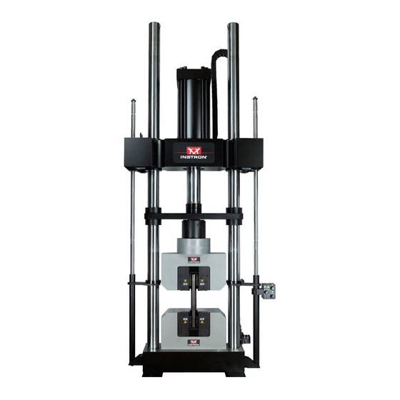
Purpose Warning If the equipment is used in a manner not specified by Instron, the protection provided by the equipment may be impaired. Injury to personnel or damage to the system may result. Be sure to read and understand the material presented in these instructions and in any other accompanying instructions. - Page 11 About these instructions Figure 1. KPX testing systems - various configurations shown. Product Support: www.instron.com...
-
Page 12: Frame Configuration Options
Instructions on the installation, use and maintenance of Instron testing accessories are provided separately with each testing accessory. A variety of testing accessories are available. Contact your Instron Sales Representative for more information. -
Page 13: System Identification
HPS - This serial number can be found on the rear of the HPS (rear cover of console must be removed). The frame serial tag includes other important system information, including information on your frame’s configuration. Frame configuration information can also be found on your Instron quote. Refer to “Frame configuration options”... -
Page 14: Product Support
In the US and Canada, you can call directly at 1-800-473-7838. Product documentation Instron offers a comprehensive range of documentation to help you get the most out of your Instron products. Depending on what you have purchased, your documentation may include some or all of the... -
Page 15: Calibration And Verification
ASTM, ISO, and EN standards require the system be calibrated when it is installed or when it is moved or relocated. Instron calibrates the system at the factory, and provides a record of readings for the load cell. This frame may be verified on-site to ASTM E-4, BS 1610, DIN 51221, ISO 7500/1, EN 10002-2, JIS B7721, JIS B773 or AFNOR A03-501 standards. - Page 16 Chapter 1: Introduction This page is intentionally blank. M47-17036-EN...
-
Page 17: Chapter 2 Installation Notes
If factory rationalization was purchased, these transducers will be requested 2-3 weeks prior to shipment of the system in order to integrate them. Some instruments can be rationalized separately from the shipment of the system, if necessary, to maintain your testing commitments. Contact your local Instron office for more information. -
Page 18: Interconnections
Chapter 2: Installation Notes Interconnections The following interconnection information is provided for reference. It is not intended to be a complete step-by-step installation procedure, but it does provide a general guideline of what and how system components should be interconnected. Depending on the components supplied with your system, all the interconnections listed may not be necessary for your system. - Page 19 Interconnections Electric connections A through F Hydraulic connections 1 through 6 (typical connections shown, not all connections may be used by your system) Figure 3. HPS connection panels. Product Support: www.instron.com...
-
Page 20: Electrical Interconnections
Chapter 2: Installation Notes Electrical interconnections Before making electrical interconnections, all system components (including the 59 Series control unit, pendant station and computer system) should be unpacked and in place at the installation site. Also, the computer system components can and should be interconnected as outlined by the computer manufacturer. - Page 21 1. If the position cable was not connected to the position encoder as stated in Chapter 4 of the System Pre- Installation Manual (supplied separately), then the position cable must be connected now. Expansion port (optional) Rear Panel Front Panel Figure 4. 59 Series control unit connection panels. Product Support: www.instron.com...
-
Page 22: Software And Computer Setup
Chapter 2: Installation Notes Software and computer setup When a new computer system is purchased as part of the testing system and is supplied from the factory, or if a customer supplied computer was returned to the factory for integration with the system, then the computer system and controlling software were set up at the factory before shipment. - Page 23 Interconnections Windows XP operating system Windows 7 operating system Figure 5. Local area connection properties. Figure 6. Internet protocol properties. Product Support: www.instron.com...
- Page 24 Ethernet connection). The MAC address is case sensitive. The first six digits (00-90-C2) indicate that the EFI is an Instron device. The last six digits are unique to that EFI to ensure that Partner only communicates with that specific EFI (Figure viii.
- Page 25 Partner interface type selection. Figure 9. Partner MAC address entry. b. For systems with Bluehill software, perform the following: Start Bluehill. Select the Admin button. (Ensure no methods are open.) iii. On the Admin page, select Configuration. Product Support: www.instron.com...
- Page 26 59-Series control unit (usually below the ethernet connection). The first six digits (00-90-C2) indicate that the EFI is an Instron device. The last six digits are unique to that EFI to ensure that Bluehill only communicates with that specific EFI.
-
Page 27: Initial Startup
A 6 mm hex key (supplied) • All tools for your frame model that are listed in Table 3 Table 3. Tools required per frame model. Frame Model Instron Supplied Tools Customer Supplied Tools • 5/16 in hex-bit socket 600KPX-J3 3/4 in square-drive wrench •... - Page 28 Chapter 2: Installation Notes 3. Ensure that the test space is clear - there should be no fixtures installed in the test space. This would exclude any fixtures that were installed at the factory and remained in the test space for shipment. These fixtures can remain in the test space.
- Page 29 Identifying the clamp bolts on frames with a J3-style crosshead. Check that the frame is enabled. If the frame will not enable, see “Troubleshooting” on page 47, specifically Problem No. 2 of the table. Once any problems are corrected, enable the frame. Product Support: www.instron.com...
- Page 30 Chapter 2: Installation Notes Pump Start FRAME READY 8. Start the HPS by pressing the button on the HPS controls; the indicator will illuminate. Immediately check the position of the piston within the hydraulic cylinder, the piston should be positioned so that it is neither fully retracted nor fully extended. Use the jog controls to move the piston if necessary - typically a separation of 6 mm (0.25 in) is sufficient.
-
Page 31: Install Covers For Crosshead Lock Cylinders - J3-Style Crosshead
Mounting hardware is supplied. Slide the covers down over the ends of the crosshead from the top. Secure in place with cap screws, refer to Figure All Frames Except 2000KPX-J3 Frames 2000KPX-J3 Frames Figure 13. Installing lock cylinder covers on frames with a J3-style crosshead. Product Support: www.instron.com... -
Page 32: Optional Accessories
Semi-permanently mounted accessories are typically not installed until the system is fully operational. Typically the Instron service engineer will assist with this during installation of the system. For more detailed information on these accessories, refer to the individual instructions that are included with each accessory. -
Page 33: Chapter 3 Additional System Details
Chapter 3 Additional System Details • Frame ..............33 •... - Page 34 Chapter 3: Additional System Details Frame with a J1-style crosshead Frame with a J3-style crosshead 1. Position encoder 10. Rod 2. Hydraulic cylinder 11. Pre-load device 3. Crosshead 12. Guide plate 4. Column 13. Bearing and wiper assembly 5. Test space 14.
- Page 35 46. • J4-style crosshead - The crosshead is fixed; no adjustment is possible. Table 5. Number of lock cylinders used for frames with a J3-style crosshead. Frame Model Number of Lock Cylinders 600KPX-J3, 1500KPX-J3 1000KPX-J3 2000KPX-J3 Product Support: www.instron.com...
-
Page 36: Crosshead Support Collars
Chapter 3: Additional System Details Crosshead support collars All KPX frames with either a J1-style or J3-style crosshead have crosshead support collars that mount to each column, as shown in Figure 15 on page 35. The crosshead support collars have several purposes: •... -
Page 37: Hydraulic Cylinder And Anti-Rotation
34) that is mounted to the end of the hydraulic cylinder rod and to two columns. The guide plate is equipped with bearing and wiper assemblies to assure smooth operation as it moves up and down on the columns. Product Support: www.instron.com... -
Page 38: Optional Accessories
Chapter 3: Additional System Details Optional accessories Instron offers a wide variety of testing accessories that can be used with the KPX frame. Some are designed to be mounted temporarily in the frame, while others are designed to be mounted semi- permanently to the frame. -
Page 39: Controls And Electronics
10V outputs via BNC connectors. A 25 pin D connector provides recorder pulse drive, 4 logic line outputs and 4 logic line inputs to trigger internal and external events. SERVICE: A connection for optional communications modem for remote diagnostics. Product Support: www.instron.com... - Page 40 “P” indicates the all self- tests have passed. If the LEDs should flash the letter “F” at any time during the sequence, this indicates that a self-test has failed. If this occurs, you should contact your local Instron Services department as directed on page for assistance in troubleshooting the failure.
-
Page 41: Computer System And Controlling Software
On-line Help system or to the manual provided. Computer systems are typically purchased from Instron with the testing system, however they may be customer supplied. If this is the case, refer to any information provided by the computer vendor in regards to its operation, warranty, etc. -
Page 42: Hydraulic System
Chapter 3: Additional System Details Hydraulic system Introduction Warning Shut down the HPS and discharge hydraulic pressure before disconnecting any hydraulic fluid coupling. Do not disconnect any hydraulic coupling without first shutting down the HPS and discharging stored pressure to zero. Tie down or otherwise secure all pressurized hoses to prevent movement during system operation and to prevent the hose from whipping about in the event of a rupture. - Page 43 19) is placed on the reservoir’s fill hole to allow the reservoir to breathe while preventing dirt from entering the reservoir. It can be easily removed for access to the reservoir. For maintenance of the air filter, refer to maintenance information provided in the System Operating Instructions (supplied separately). Product Support: www.instron.com...
-
Page 44: Pump And Motor
This flow control adjustment is set at the factory and should not require further adjustment. Any adjustments should only be made by an Instron service engineer. For pump and motor maintenance, refer to the separately supplied manufacturer’s information. -
Page 45: Manifold Assemblies
System pressure is set at the factory and should not require further adjustment. Any adjustments should only be made by an Instron service engineer. System relief valve: The system relief valve provides pressure relief for the system to prevent damage to system components in the event that the pump builds too much pressure. -
Page 46: Lifts And Locks Manifold Assembly
All relief valves, reducing valves, pressure switches, etc. are set at the factory to their proper operating pressure. They should not need further adjustment. If you feel adjustment is necessary, contact your local Instron Services department as directed on page 14. Any adjustments should only be made by an Instron service engineer. -
Page 47: Troubleshooting
If the problem cannot be determined through the chart, contact your local Instron Services department as directed on page 14. Another option would be to check the listing of Frequently Asked Questions (FAQs), available on the Instron website (www.instron.com), for a description/solution to your problem. - Page 48 Check the user control panel cable for stating “Control Panel Watchdog with the user control panel damage. If damage is found contact your Timeout” local Instron Services department as directed on page 14. • After opening a procedure the HPS The frame is not enabled...
- Page 49 “Sensor Loop Failure” selected is too fast load/stress control during the yield portion of a test. Select position or strain control and restart test, or contact your local Instron Services department as directed on page 14. Tension/Compression Tension/Compression Place the...
- Page 50 Verify that the software version is controlling software is in use 8.2a or above for Partner, or 2.15 or above for Bluehill • If none of the above correct the problem, then contact your local Instron Services department as directed on page M47-17036-EN...
- Page 51 Frame Partner Software Bluehill Software Figure 20. Controlling software error messages. Figure 21. Internet protocol properties. Product Support: www.instron.com...
- Page 52 Chapter 3: Additional System Details This page is intentionally blank. M47-17036-EN...
-
Page 53: Chapter 4 Parts Replacement
• Fuses All other parts replacement should be done by an Instron service engineer. For assistance with replacement of any part, contact your local Instron Services department as directed on page 14. -
Page 54: Replacement Of Fuses
Chapter 4: Parts Replacement Replacement of fuses The system is equipped with fuses as outlined in Table Table 10. Fuse information. Instron Fuse Description Specifications Part Number Quantity Fuses in power entry module of 59 Series control 5 amp, unit... -
Page 55: Inspect/Replace 59 Series Power Entry Module Fuses
If a load cell has been overloaded, the load-sensitive member may be permanently deformed to the extent that the proper dimensional alignments inside the cell are no longer maintained. If you suspect that a cell may be damaged, contact your local Instron Services department as directed on page to arrange returning the load cell for analysis and possible repair. - Page 56 Chapter 4: Parts Replacement This page is intentionally blank. M47-17036-EN...
- Page 58 Product Support: www.instron.com...
Need help?
Do you have a question about the KPX Series and is the answer not in the manual?
Questions and answers