
Related Manuals for Instron KPX


Summary of Contents for Instron KPX
- Page 1 Industrial Products Group Model KPX Static Hydraulic Universal Testing System Operating Instructions M47-17035-EN Revision A www.instron.com The difference is measurable ®...
- Page 2 Instron is a registered trademark of Illinois Tool Works Inc. (ITW). Other names, logos, icons and marks identifying Instron products and services referenced herein are trademarks of ITW and may not be used without the prior written permission of ITW.
- Page 3 Caution is used where a hazard may lead to damage to equipment or to loss of data. Instron products, to the best of its knowledge, comply with various national and international safety standards, in as much as they apply to materials and structural testing.
- Page 4 Preliminary Pages Warnings Hazard - Press the Emergency Stop button whenever you consider that an unsafe condition exists. The Emergency Stop button removes hydraulic power or electrical drive from the testing system and brings the hazardous elements of the system to a stop as quickly as possible.
- Page 5 Disconnect equipment from the electrical power supply before removing any electrical safety covers or replacing fuses. Do not reconnect the power source while the covers are removed. Refit covers as soon as possible. Product Support: www.instron.com...
- Page 6 Preliminary Pages Warnings Rotating Machinery Hazard - Disconnect power supplies before removing the covers to rotating machinery. Disconnect equipment from all power supplies before removing any cover which gives access to rotating machinery. Do not reconnect any power supply while the covers are removed unless you are specifically instructed to do so in the manual.
-
Page 7: Table Of Contents
Recommended procedure - 2000KPX frames ....... . Product Support: www.instron.com... - Page 8 Preliminary Pages Run a test............... Shut down the system .
-
Page 9: Chapter 1 Introduction
Software test methods that are appropriate for your testing requirements are available. These instructions do not include the development of test methods within the materials testing software. This is covered in more advanced training that can be provided by Instron Service and Training departments. -
Page 10: System Overview
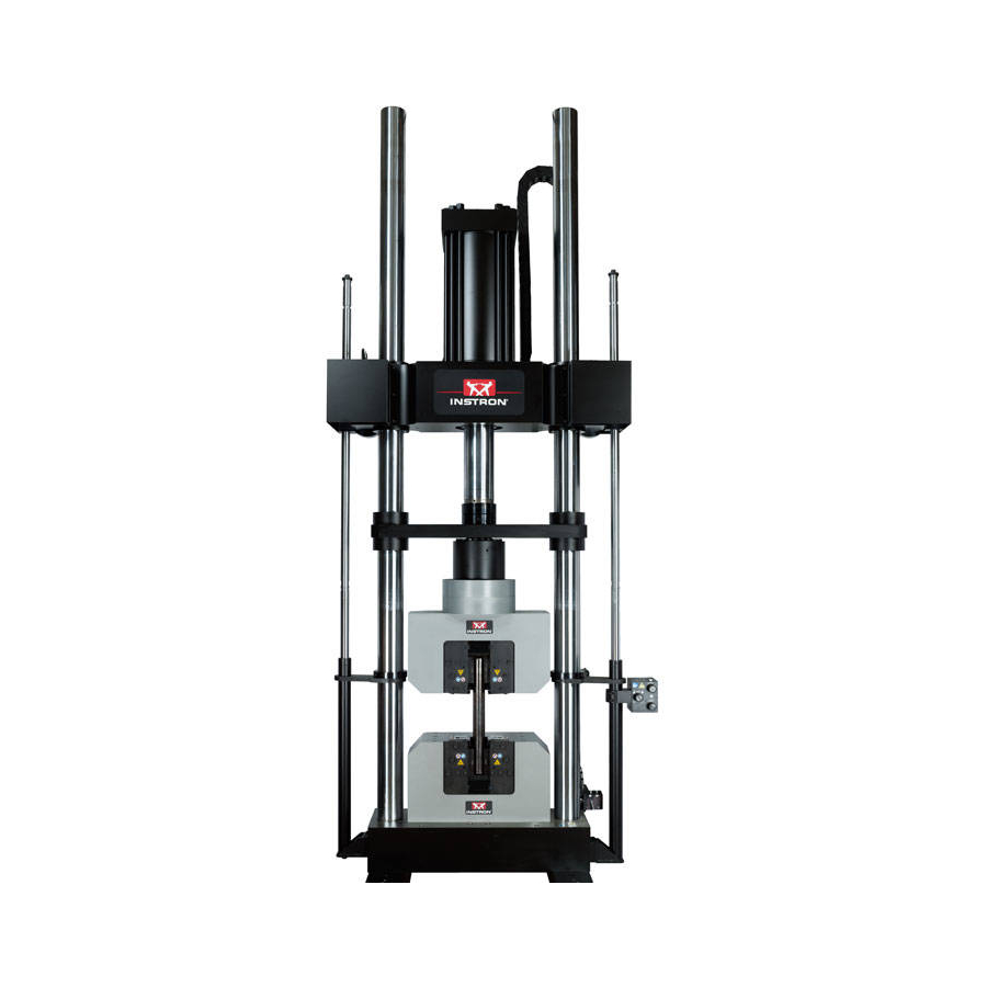
Purpose Warning If the equipment is used in a manner not specified by Instron, the protection provided by the equipment may be impaired. Injury to personnel or damage to the system may result. Be sure to read and understand the material presented in these instructions and in any other accompanying instructions. - Page 11 System overview Figure 1. KPX testing systems - various configurations shown. Product Support: www.instron.com...
-
Page 12: Frame Configuration Options
Instructions on the installation, use and maintenance of Instron testing accessories are provided separately with each testing accessory. A variety of testing accessories are available. Contact your Instron Sales Representative for more information. -
Page 13: System Identification
HPS - This serial number can be found on the rear of the HPS (rear cover of console must be removed). The frame serial tag includes other important system information, including information on your frame’s configuration. Frame configuration information can also be found on your Instron quote. Refer to “Frame configuration options”... -
Page 14: Frame Components
For proper operation of the system, it is important to be able to identify and to understand the basic function of these components. Figure 2. KPX frame components - 2 column frame shown - for legend see Table M47-17035-EN... - Page 15 Provide hydraulic adjustment of the crosshead on the columns. Refer to “Adjust the position of a J3-style crosshead” on page for more information. Provided on J3-style crossheads only. 8. Base Provides mounting surface for fixtures (purchased separately), refer to “Mount fixtures” on page for more information. Product Support: www.instron.com...
-
Page 16: System Control Components
Chapter 1: Introduction System control components Refer to Table 2 to identify control components of the system. For proper operation of the system, it is important to be able to identify and to understand the basic function of these components. Table 2. -
Page 17: System Safety And Information Labeling
High pressure hazard - Indicates that a hazard exists from high pressure. Do not adjust or reset any pressure settings until you have read and understood the operator’s manual. Personal injury or damage to equipment may result. Most pressure settings should only be adjusted by an Instron service engineer. -
Page 18: Product Support
In the US and Canada, you can call directly at 1-800-473-7838. Product documentation Instron offers a comprehensive range of documentation to help you get the most out of your Instron products. Depending on what you have purchased, your documentation may include some or all of the... -
Page 19: Chapter 2 Specifications
The system can operate in servo control mode only through an Instron Materials Testing Software package. The system must never be left unattended while in operation. -
Page 20: Frame
Frame The technical specifications for the various standard KPX frames can be found in Table 5. If unsure of the options included with your frame, check the model number listed on the frame’s serial number tag; it includes option designations. - Page 21 Frame Table 5. KPX frame technical specifications. (Continued) Specification 600KPX 1000KPX 1500KPX 2000KPX 0 to 2921 mm 0 to 2921 mm (0 to 115 in) (0 to 115 in) 0 to 2540 mm 0 to 3226 mm 0 to 3226 mm...
- Page 22 Chapter 2: Specifications Table 5. KPX frame technical specifications. (Continued) Specification 600KPX 1000KPX 1500KPX 2000KPX Overall Frame Area (width (F) x depth (G)) 1162 x 864 mm 1283 x 1219 mm 1473 x 1219 mm (45.75 x 34 in) (50.5 x 48 in)
- Page 23 (position) readout should not be used as the primary strain measuring device where an extensometer on the specimen is clearly warranted. Frame compliance can be accounted for, to some extent, by Instron software. 10.At speeds below approximately 0.1 mm/min (0.004 in/min) the hydraulic cylinder moves in increments approximately equal to these values and can be seen as load steps depending on the specimen stiffness and load range.
-
Page 24: Hydraulic Power Supply Physical Dimensions
Real-time closed-loop control Real-time data acquisition Data Transfer to Computer 1000 Hz Transducer Inputs Standard Instron rationalized transducers Any 0-10 V analog DC input Transducer Resolution 1 part in 500,000 of +/- full scale (19 bits) Load Measurement Accuracy +/- 0.5% of reading down to 1/500 of load cell capacity Linearity +/- 0.25% of reading over a range of 0.2% to 100% of capacity... -
Page 25: Environmental Conditions
HPS Model Duty Cycle Duty Cycle 600KPX-D17 V22h 0.84 kW (2856 BTU/hour) 1.79 kW (6120 BTU/hour) 1000KPX-D18, V22e 0.12 kW (392 BTU/hour) 0.38 kW (1279 BTU/hour) 1500KPX-D18 2000KPX-D19 V22f 0.12 kW (392 BTU/hour) 0.38 kW (1279 BTU/hour) Product Support: www.instron.com... -
Page 26: Noise Level
Chapter 2: Specifications Noise level The A-weighted emission sound pressure level generated by the testing system under normal operating conditions does not exceed 70 dBA. The peak C-weighted instantaneous sound pressure value does not exceed 63 Pa. Since many variables (such as room layout) affect noise levels, it can not be assumed that these readings will be equal to those in the field. -
Page 27: Chapter 3 Operation
Chapter 3 Operation • Operation of controls ............27 •... - Page 28 Chapter 3: Operation Table 10. Control functions. (Continued) Control Location Description Tension/compression HPS control Set the switch to the desired testing direction before starting a test. If the control switch switch is not set to the correct direction for the test, the frame will not respond as directed by the controls.
- Page 29 Provides an indication of self-tests that are performed by the controls control unit when the system is powered up and is also an indicator of system status. System status is normal when the indicator is green and the indicator is blinking red. Product Support: www.instron.com...
- Page 30 Chapter 3: Operation Figure 5. User control panel. M47-17035-EN...
-
Page 31: Operation Of Hps
Some bolt patterns are designed for the mounting of specific standard Instron accessories or fixtures, while others are more general for the mounting of a wide range of standard Instron accessories or fixtures. Any bolt pattern can be used for the mounting of customer fixtures; appropriate adaptation may be necessary. -
Page 32: Start The System
Chapter 3: Operation Start the system This document presumes that customer training (by Instron service personnel) has been completed and that at least one procedure has been created in the controlling software. Before operating the system: • Familiarize yourself with the operating features and controls described in these instructions and in all other accompanying documentation for the controlling software. -
Page 33: Change Height Of Test Opening - J1-Style Or J3-Style Crosshead
A hex socket, for use with torque wrench and ratchet wrench, refer to Table 12 on page for size needed (supplied) • A torque wrench (supplied) • A ratchet wrench (supplied) Recommended procedure Start the system; see page 32. Start the HPS. Product Support: www.instron.com... - Page 34 Chapter 3: Operation 2. Extend or retract the hydraulic cylinder so that it has enough stroke in the appropriate direction to obtain the desired crosshead height: • To lower the crosshead, extend the hydraulic cylinder so that it has enough stroke to retract and lower the crosshead.
- Page 35 Do not over torque the bolts. Adjust the crosshead support collars on the columns so that they are in contact with the bottom of the crosshead (use hex-bit socket and ratchet wrench). Secure the crosshead support collars to the Product Support: www.instron.com...
- Page 36 Chapter 3: Operation columns. Tighten the cap screws to the torque specified in Table 11 on page (use hex-bit socket and torque wrench). 8. Normal operation can now resume. View C View A View B View D Loosening Initial tightening of Tightening of Subsequent tensioners with...
-
Page 37: Adjust The Position Of A J3-Style Crosshead
Any fixture or specimen installed in the frame may not align. • If the crosshead is positioned with the crosshead lift cylinders fully extended and a tension or compression load is applied, the crosshead could slip until it reaches a level position. Product Support: www.instron.com... -
Page 38: Equipment Required
Chapter 3: Operation • If the crosshead is positioned with the crosshead lift cylinders fully retracted and a tension load is applied, the crosshead will not be able to absorb the shock generated by a specimen break. This will cause the shock to be transferred to other components of the frame and may cause damage to the frame. - Page 39 Remove each retaining ring (6) from its lower notch (use 4 mm hex key). xiv. Install each retaining ring in its upper notch. Be sure that a flat area of the retaining ring is facing outward, so that the setscrew will seat on the flat area. Product Support: www.instron.com...
- Page 40 Chapter 3: Operation RAISE xv. Open the valve until each retaining ring is fully seated in its lift block. Tighten each RAISE setscrew. Close the valve. xvi. Go to step to continue crosshead adjustment. b. To move the crosshead to the low travel range: Warning Failure to perform this procedure as directed may result in death, serious bodily injury or damage to the frame.
- Page 41 Unclamp the crosshead - open the locks control valve by rotating it counterclockwise. RAISE LOWER 8. Open either the valve until the crosshead is in the desired position and then close the valve. 9. Clamp the crosshead - be sure to fully close the locks control valve. Product Support: www.instron.com...
-
Page 42: Recommended Procedure - 2000Kpx Frames
Chapter 3: Operation Do not attempt to use the Jog controls to operate the hydraulic cylinder until approximately 1 minute has passed. This allows the HPS to build enough pressure to clamp the crosshead lock cylinders. The noise level of the HPS is a good indication of when this occurs; the noise level will decrease once it has built enough pressure and the crosshead lock cylinders are clamped. - Page 43 Verify that both lifts control valves are closed and that both height adjustment pins are in place. Start the system; see page 32. Start the HPS. iii. Be sure that the hydraulic cylinder is fully retracted. Product Support: www.instron.com...
- Page 44 Chapter 3: Operation Lift cylinder extensions in high Lift cylinder extensions in low range position range position 1. Lift cylinder extension 3. Crosshead 2. Crosshead lift cylinder 4. Adjustment pin Figure 10. 2000KPX frames with a J3-style crosshead. RAISE iv. Be sure the locks control valve is closed. Open the valve for five seconds and then close it.
- Page 45 (use hex-bit socket and ratchet wrench). Secure the crosshead support collars to the columns. Tighten the cap screws to the torque specified in Table 11 on page (use hex-bit socket and torque wrench). 11. Normal operation can resume. Product Support: www.instron.com...
-
Page 46: Run A Test
This document presumes that customer training (by Instron Service Engineer) has been completed and that at least one procedure has been created in the controlling software. - Page 47 Use the jog controls to move the piston if necessary - typically a separation of 6 mm (0.25 in) is sufficient. Product Support: www.instron.com...
-
Page 48: Shut Down The System
Chapter 3: Operation Shut down the system It is recommended that the system as a whole (frame, control unit, HPS, computer system, peripherals, etc.) be shut down at the end of each working day or anytime it will sit idle for long periods of time. The procedure to shut down the system is as follows: 1. -
Page 49: Loss Of Power
On loss of power, when the servo blocker valve closes, the hydraulic cylinder will drift upward approximately 2 mm (0.08 in). Any instrument in the load train that is sensitive to a tensile load may be damaged (i.e. extensometers, low range load cells, etc.). Product Support: www.instron.com... - Page 50 Chapter 3: Operation This page is intentionally blank. M47-17035-EN...
-
Page 51: Maintenance
General maintenance recommendations Only the maintenance procedures outlined in these instructions should be performed by the customer or their representative. All other maintenance and repairs should be performed by Instron Service personnel only. -
Page 52: Preventative Maintenance Schedule
Chapter 4: Maintenance Preventative maintenance schedule Table 13 outlines a recommended preventative maintenance schedule for system components. Table 13. Recommended preventative maintenance schedule. Frequency Component Maintenance Task • Daily: System Make daily checks of system; see page 53. • Monthly: Visually inspect all hoses (exposed and hidden) and around the base of System the frame and HPS for signs of oil leakage. -
Page 53: Make Daily Checks Of System
If any of these checks reveal a potential problem, the problem should be investigated and corrected before the system is operated. For assistance in troubleshooting the system, contact your local Instron Services department as directed on page 18. -
Page 54: Remove And Install Console Covers
Chapter 4: Maintenance Remove and install console covers To perform any maintenance on the HPS it is necessary to remove the rear cover from the console. Loosen and remove the seven M6 button head cap screws (2, Figure 11) from the rear cover (1). Be careful of the electrical wires to the fan. -
Page 55: Electronics
HPS. Tighten any loose connections that you may find. • Inspect all cables for deterioration. Check for abrasions, cuts, etc. Replace cables as necessary. If you notice any problems resulting from this inspection, contact your local Instron Services department as directed on page for immediate assistance. -
Page 56: Crosshead
Chapter 4: Maintenance a short period of time is abnormal; contact your local Instron Services department as directed on page for immediate assistance. • Clean the rod of the hydraulic cylinder. Completely extend the hydraulic cylinder and wipe the rod with a soft cotton cloth to remove oil residue and debris. -
Page 57: Clean The Columns
Table 11 on page (use hex-bit socket and torque wrench). 8. If you notice any problems resulting from this inspection, contact your local Instron Services department as directed on page for immediate assistance. Clean the columns It is necessary to clean the columns at the frequency stated in the “Preventative maintenance... -
Page 58: Hydraulic Power Supply (Hps)
If the oil appears dirty, it should be changed (see “Change the oil” page 60). In the United States and Canada, an oil sample test kit is available for purchase from Instron Services; contact your local Instron Services department as directed on page for more information about the test kit. - Page 59 6. Air breather filter 11. Connection panels 2. Motor Fill hole a. Hydraulic 3. System pressure gauge 8. Sight gauge b. Electric 4. Oil filter 9. Reservoir 5. Relief valve RV1 10. Servo manifold Figure 12. Components of the HPS. Product Support: www.instron.com...
-
Page 60: Change The Oil
Hydraulic fluid, for fluid specifications and amount required see “Oil type and quantity” page • New oil filter element - for Instron part number see Table 15 on page • New air breather filter - for Instron part number see... - Page 61 8. 12. Insert a clean funnel with a mesh filter into the fill hole and fill the reservoir with the recommended hydraulic fluid. Fill the reservoir to the top of the sight gauge. Product Support: www.instron.com...
-
Page 62: Change The Air Breather Filter
Table 15 on page When ordered from Instron, the air breather filter includes a new air breather fitting and plastic screen. The only part needed is the air breather filter. However, you can replace the existing air breather fitting and plastic screen with the new parts if desired or necessary (due to damage, etc.). -
Page 63: Replace The Hydraulic Hoses
“Preventative maintenance schedule” on page 52. Remove the filter from the filter guard through the opening in the top of the guard. Clean the filter with water or vacuum as necessary. Return the filter to the filter guard. Product Support: www.instron.com... -
Page 64: Ancillary Parts
Chapter 4: Maintenance Ancillary parts KPX systems are provided with several operating tools and other accessories that are either: required to complete installation of the frame; required for use or maintenance of frame; or required for set up of accessories on the frame. These ancillary parts are included with the frame upon delivery. Ancillary... - Page 65 Tighten and loosen various fasteners 300-8875-9290 1.5 - 10 mm ball end 1. Part numbers are listed for reference only. Some parts can not be ordered using these numbers; contact your local Instron Services department as directed on page to order parts.
-
Page 66: Consumable Parts
Chapter 4: Maintenance Consumable parts KPX systems are designed to require very few parts to be replaced during their lifetime. These consumable parts are listed in Table 15. The replacement frequency of each part, or the condition that indicates that replacement is necessary, is discussed throughout this chapter. -
Page 67: Appendix Ace Certificate
900 Liberty Street, Grove City, PA, 16127, USA Name and address of the person authorised to compile the technical file: Name: Jonathan Snell Address: Instron - Division of ITW Limited, Coronation Road, High Wycombe, Buckinghamshire, HP12 3SY, United Kingdom Herewith we declare that Model Number: Serial Number:... - Page 68 Appendix : CE Certificate This page is intentionally blank.
- Page 70 Product Support: www.instron.com...
Need help?
Do you have a question about the KPX and is the answer not in the manual?
Questions and answers