Page 1
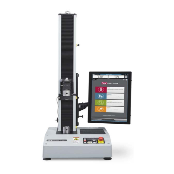
3400 Series Single Column Table Model Operator’s Guide M10-17313-EN Revision B...
Page 2
Instron is a registered trademark of Illinois Tool Works Inc. (ITW). Other names, logos, icons and marks identifying Instron products and services referenced herein are trademarks of ITW and may not be used without the prior written permission of ITW.
Page 3
Caution is used where a hazard may lead to damage to equipment or to loss of data. Instron products, to the best of its knowledge, comply with various national and international safety standards, in as much as they apply to materials and structural testing.
Page 4
Preliminary Pages Warnings Hazard - Press the Emergency Stop button whenever you consider that an unsafe condition exists. The Emergency Stop button removes hydraulic power or electrical drive from the testing system and brings the hazardous elements of the system to a stop as quickly as possible.
Page 5
During system operation, keep away from the operating envelope of the robot. De-activate the robot before entering the envelope for any purpose, such as reloading the specimen magazine. Product Support: www.instron.com...
Page 6
Preliminary Pages Warnings Hazard - Set the appropriate limits before performing loop tuning or running waveforms or tests. Operational limits are included within your testing system to suspend motion or shut off the system when upper and/or lower bounds of actuator or crosshead travel, or force or strain, are reached during testing.
Page 7
Apply the specified torque to all load string fasteners and the correct setting to wedge washers or spiral washers. Visually inspect highly stressed components such as grips and threaded adapters prior to every fatigue test for signs of wear or fatigue damage. Product Support: www.instron.com...
Page 13
(carried out by an ® Instron service engineer for first-time installation) • ® configuring the system before you start testing (carried out by an Instron service engineer for first-time installation) • routine maintenance of the system •...
• perform routine maintenance of the system ® These instructions do not include the development of Bluehill test methods. This is ® covered in more advanced training that can be provided by the Instron Service and Training departments. M10-17313-EN...
System Description and Terminology System Description and Terminology ® Figure 1. 3400 Single Column Table Model with Bluehill Operator Dashboard - Front View Product Support: www.instron.com...
® contacting extensometer. Contact your regional Instron office or check our web site at www.instron.com for assistance with Instron’s grips and fixtures. The following table defines the components of the testing system: M10-17313-EN...
The load cell converts this load into an electrical signal that the software measures and displays. ® ® Bluehill Instron Software testing software that controls the testing system, running tests and analyzing test data to produce test results. Specimen A single piece of material to be tested.
Frame control panel - holds all the controls and indicators for the testing system. Software ® Control of the testing system is carried out via Instron Bluehill software. Setting test parameters, operating the system, and collecting test data is done through the software program.
Page 21
Read the manual Read and understand the operator’s manual before using the machine. Crosshead direction Indicates the direction to turn the pulley to manually move the crosshead upward. Pulleys can be turned by hand when power is disabled. Product Support: www.instron.com...
For advice on the disposal of electrical and electronic equipment in your country, contact your local Instron representative. Conformity with EU directives ® Instron declares under our sole responsibility that 34SC and 34TM testing systems are in conformity with all relevant provisions of the following regulations: •...
If you cannot find answers in these sources, contact Instron Service directly. A list of ® Instron offices is available on our website at www.instron.com. In the US and Canada, you can call directly at 1-800-473-7838. Product Documentation ® Instron offers a comprehensive range of documentation to help you get the most out of your Instron products.
Page 24
Chapter: Introduction You can find a copy of the Preinstallation manual on the USB drive provided with your ® system. This drive contains your Bluehill software. The Preinstallation manuals are stored in a directory named: Frame Manuals The following table lists the manuals for single column table model load frames: Model number Manual number 34SC-05 (0.5 kN)
Each of the following sections describes a specific hazard zone of the testing system and lists the most common risks for testing using this equipment. Use the information in the following sections, together with the instructions in the remainder of this manual, to conduct your own risk assessment. Product Support: www.instron.com...
Chapter: Risk reduction and safe use Rapid crosshead motion Warning Crush hazard to fingers or hands. This hazard relates to grips and fixtures coming together as a result of rapid crosshead motion, crushing hands or fingers. For example, an operator inadvertently commands the system to jog or return while their hands are in test area.
Page 27
Use a specimen insertion tool to keep fingers out of the space between the fixtures. • Use an interlocked shield to limit or disallow motion when the shield door is open. When the space is less than 25mm, the crush hazard is very significant, so this is the best option. Product Support: www.instron.com...
Chapter: Risk reduction and safe use Pinching fingers between grip jaw faces Warning Pinch hazard to fingers. This hazard relates to grip jaws closing quickly, pinching fingers. Recommendations For 2712 Series pneumatic grips: • In the documentation supplied with the grips, read and follow the safety recommendations for installing a specimen.
This hazard relates to brittle or composite specimens that can explode when they break. Recommendations For less dangerous debris (specimen dust or fibers, for example): • Use personal protection equipment (for example safety glasses). For more dangerous projectile debris (brittle composite specimens, for example): • Use an interlocked shield. Product Support: www.instron.com...
Chapter: Risk reduction and safe use Operator Protection Overview The majority of hazards for operating materials testing systems are associated with: • rapid movement of the crosshead causing crush injuries • rapid closing of pneumatic grips causing pinch injuries ® Operator Protection in Bluehill provides a mechanism that lets you limit crosshead jog speed and reduce grip closing pressure while you are setting up a test.
Refer to Figure 3 on page and follow the procedure. Figure 3. Adjust the leveling feet You need the following equipment (supplied in the ancillary parts kit unless specified otherwise): Product Support: www.instron.com...
Chapter: Installation • Spirit level (not supplied) • 19mm combination wrench (part no. P632-484) • 16mm thin open-ended wrench (part no. P632-482) Caution Make sure that the full weight of the frame is bearing down on the feet. If it is not, you will not be able to adjust the feet.
Page 33
Observe the CEE wire color code as follows: • Brown - high (live) • Light blue - low (neutral) Product Support: www.instron.com...
Chapter: Installation • Green and yellow - earth (ground) Set the input voltage The load frame voltage is factory set according to the voltage that was specified at the time of purchase. Use the following procedures only if the facility power source does not match the frame voltage setting.
Page 35
2. Insert a small flat-head screwdriver into the middle of the connector and pry out the fuse holder (1), as shown below. 3. Remove the fuse holder (1) from the power input connector, exposing the voltage selector card (2) as shown below. Product Support: www.instron.com...
Page 36
Chapter: Installation 4. Using long-nose pliers, remove the voltage selector card (2) as shown below. The voltage indicator pin is labeled (3). 5. Position the voltage selector card so the indicator pin (3) points upward, as shown below. Holding the pin in this position, rotate the card until the required voltage setting shows at the bottom of the card.
10. Before you carry out any testing, perform the procedure described in “First time startup” on page 47. System components ® Instron Service installs your testing system. These diagrams and instructions are provided as a reference if you need to move the system after the initial installation. Product Support: www.instron.com...
Page 41
Figure 7 Label Component More detail Encoder connector Connects to various accessories, including AVE2 and AutoX extensometers Foot switch connector Status indicators PIP jack Strain connectors Optional Status indicators Force connector Connects to load cell Sync connector Product Support: www.instron.com...
Page 42
Label Component More detail ® Service connectors For use by Instron Service only Ground connection detail If the electrical supply is not grounded, you must use this functional ground connection to connect the frame to a suitable ground in the building.
5. Use the cable clips on the column to secure the load cell cable and pneumatic grip connections (see “Single column load frame” on page 38). ® 6. Instron systems provide an option to measure strain. If your system is equipped to measure strain, connect the extensometer to the STRAIN 1 connection on the controller (see “Controller connections detail”...
® testing machine using Bluehill software. Adjustment and connection ® ® Instron Service will install the Bluehill Operator Dashboard on your system. ® 1. You can adjust the height of the Bluehill Operator Dashboard for the comfort of different operators. Loosen the lock (1 in...
Page 45
If you need to move the testing system you must disconnect and remove the Bluehill Operator Dashboard as follows: 1. Ensure that the power switch is set to Off and the mains power cable is disconnected. ® 2. Disconnect all cables that connect to or from the Bluehill Operator Dashboard. Product Support: www.instron.com...
Page 46
Chapter: Installation Figure 10. Mounting arm 3. If necessary, loosen the set screw on the side of the “elbow” on the mounting arm (1 Figure 10 on page 46). 4. Operate the release mechanism on top of the “elbow” (2 in Figure 10 on page 46) ®...
Operator Dashboard face down on a soft material to avoid scratching the screen. First time startup ® When the testing system is installed, you need to configure Bluehill to communicate with the testing hardware. 1. Ensure that all cables are properly installed and securely connected. Product Support: www.instron.com...
Page 48
Chapter: Installation 2. Turn the power switch on the machine to the On ( ) position. The white LED above the DISABLED indicator flashes. ® 3. Turn on the power to the Bluehill Operator Dashboard and any other accessories that make up the testing system. ®...
Pneumatic Grips ........... 66 Before you start the system, make sure you familiarize yourself with the following controls: Product Support: www.instron.com...
Chapter: Function of controls Power input connector Figure 12. Power input connector Legend for Figure 12 Label Component Power switch IEC inlet connector Fuse carrier and voltage selector access Selected voltage The power input connector, shown in Figure 12 on page 50, performs the following functions: •...
With an integrated air kit, any action that disables the frame will also open the grips. Frame Control Panel All the controls and indicators for the testing system are on the frame control panel: Product Support: www.instron.com...
Page 52
Chapter: Function of controls Figure 14. Frame Control Panel Legend for Figure 14 Label Description JOG buttons When in SET UP mode, the jog speed is restricted to 600 mm/min or less. When in CAUTION or TESTING mode, the jog speed is unrestricted, i.e. any speed up to the maximum speed for the frame.
The software controls: • setting test parameters • collecting and analyzing test data ® Refer to the Bluehill online help and reference for more details. Home Screen ® Bluehill software opens at the Home screen, with the following components: Product Support: www.instron.com...
Page 54
This button is hidden if Security is not enabled. ® Instron Connect Uses an Internet connection to check the status of the system, including verification status of transducers. Checks for software updates.
Progress messages - various messages indicating progress, for example “Opening”, “Closing” and “Generating”. Operator Protection ® Operator Protection in Bluehill provides a mechanism that lets you limit crosshead jog speed and reduce grip closing pressure while you are setting up a test. Product Support: www.instron.com...
Chapter: Function of controls Operator Protection lets an Administrator configure the testing system to be consistent with the risk assessment for that system. Access to the controls for Operator Protection is password protected. If you have ® Administrator rights you can modify Operator Protection in the Admin tab in Bluehill Operating Modes ®...
Page 57
(default value of 15 psi) The frame returns to set up mode when: • the test is paused (e.g. during extensometer removal) • after a test is complete • after a return is complete Product Support: www.instron.com...
Page 58
Chapter: Function of controls • when an interlocked shield is opened To proceed to CAUTION mode, you press the UNLOCK button. Caution ® Bluehill displays yellow border with white text, Ready to test. Yellow warning message, Keep clear of test area, disappears after a few seconds. CAUTION (yellow) LED illuminates on the frame control panel.
Crosshead speed ramps up gradually to the maximum speed of the frame. Move between modes The following table shows how the controls on the frame control panel move the system between modes to set up and run a test. Product Support: www.instron.com...
Page 60
Chapter: Function of controls Table 5. Move between modes Initial condition Action Result DISABLED SET UP Press (white) (blue) System remains in set up mode until you make a change. During this time you can: • move the crosshead at the restricted speed set up in the Admin tab, up to a maximum of 600 mm/min •...
Page 61
If you are using toggle switches on the grips to control them, the grips are at full pressure only during TESTING mode. Typical test flow “Move between modes” on page describes each of the test controls and how they are used to move between testing modes. Product Support: www.instron.com...
Chapter: Function of controls For a step-by-step description of a typical test flow using these controls, refer to “Testing a sample” on page 91. This section contains two procedures, one for systems using an interlock and one for systems without an interlock. Jog at High Speed Under normal conditions, in SET UP...
The interlock automatically transitions the system to CAUTION mode when the interlock is closed. If there is no interlock, you must press the UNLOCK button to transition to CAUTION mode. Product Support: www.instron.com...
Chapter: Function of controls Control Description Pneumatic grips Enables and disables pneumatic grips connected to the testing system with the integrated air kit. Grip control Footswitch (when pneumatic Default is . You close both grips using the grips are enabled) integrated air kit and foot switch.
(landscape orientation) to display a panel that lets you quickly include or exclude a specimen from the sample • any scrollable screen component - flick up or down, left or right to quickly scroll through the list Product Support: www.instron.com...
Other pneumatic grips can be used with the system, including operation with the integrated air kit and footswitch, but they may not be designed to utilize the full range of ® features of Operator Protection. Contact Instron Service for advice. How Operator Protection works with grips...
Page 67
(screw fully counterclockwise). Do not use the air inlet flow adjustment control to reduce air flow as you risk transitioning from initial pressure to full pressure before the grips have closed. If the Product Support: www.instron.com...
Chapter: Function of controls grips do not close completely at the initial pressure, they will close at full force when the grips transition to full pressure. In addition to the hazard caused by reducing the air flow, operation of the air inlet flow adjustment control can result in an inaccurate grip pressure reading which may disable the frame.
Page 69
3. Press the UNLOCK button to transition to CAUTION mode. The grips pressurize to full pressure. Product Support: www.instron.com...
Chapter: Function of controls 4. Within 2 seconds, press the START TEST button to start the test. If you do not start the test immediately and the system returns to SET UP mode, the grips continue at full pressure until you run a test or release the grips. The system transitions to TESTING mode.
Page 71
The system transitions to mode and the grips pressurize to full pressure. TESTING 6. Stop the test, or the test ends. The system reverts to SET UP mode and the grip pressure returns to the initial grip pressure. Product Support: www.instron.com...
Chapter: Function of controls Caution If your test ends and the specimen has stored energy, e.g. the specimen did not break, the specimen may slip out of the grips when the grip pressure reduces at the end of the test. If this could be an issue, it is recommended that you set the point of control for grips to Footswitch and use a footswitch for your tests.
It includes the load cell, grips, the specimen and any adapters that let you connect any of these components together. ® Instron Service sets up the testing machine during installation, but you may need to change one or more of these components for different types of testing.
Page 74
If you have a load cell that is not listed, contact Instron for advice on compatibility and adapters that may be available for your load cell. Table 8.
You have all the parts required for installation. Refer to the appropriate figure for your load cell in “Install the load cell” on page 76. • Mounting screws are lubricated. • A torque wrench is available. • All threads, bores and mating surfaces are clean and free of damage. Product Support: www.instron.com...
Chapter: Assemble the load string • The crosshead is positioned below its travel midpoint so that you can easily and safely access the crosshead. • The frame is in the disabled state, i.e. the white LED above the DISABLED indicator on the frame control panel is illuminated.
Page 77
11. Calibrate the load cell (refer to “Calibrate a transducer” on page 99). 12. Leave the system on for at least 15 minutes to allow the load cell circuitry to stabilize. After this warm-up period, calibrate the load cell again. Product Support: www.instron.com...
Chapter: Assemble the load string Install a 2519 load cell (capacities 1 kN through 5 kN) 2kN - 5kN Figure 16. Install a 2519 series load cell - capacities 1 kN through 5 kN Legend for Figure 16 Label Component Part number Screw, M10 x 40 201V57...
Page 79
11. Calibrate the load cell (refer to “Calibrate a transducer” on page 99). 12. Leave the system on for at least 15 minutes to allow the load cell circuitry to stabilize. After this warm-up period, calibrate the load cell again. Product Support: www.instron.com...
Chapter: Assemble the load string Install a 2530 load cell (capacities 5 N through 5 kN) 5N - 5kN Figure 17. Install a 2530 series load cell - capacities 5 N through 5 kN Legend for Figure 17 Label Component Part number Screw, M10 x 40 201V57...
Type O base adapter installed. A Type D base adapter is supplied in the ancillary parts kit. If you need to remove and re-install the base adapter, for example to change the orientation, use the following procedures. Product Support: www.instron.com...
Page 82
Chapter: Assemble the load string Remove the base adapter 1. Remove the compression spring located inside the adapter. 2. Insert a 5 mm hex key into the base adapter, ensuring that it fits into the screw at the base of the adapter. 3.
Page 83
Type D base adapter Legend for Figure 19 Label Component Part number Grip Compression spring 66-5-6 M6 screw 201V35 Clevis pin T29-515 Clevis pin clip T1223-1053 Type D base adapter T581-48 Load cell anti-rotation pin (x2) 705K84 Product Support: www.instron.com...
Chapter: Assemble the load string Label Component Part number Load frame base beam 1. Only one anti-rotation pin is visible in Figure 19 because the second pin is lined up directly behind it. 1. Insert the adapter into the base beam, noting the orientation of the locating pin or pins on the bottom of the adapter.
Insert Jaw Faces into Grips Different grips use different mechanisms for attaching jaw faces. Refer to the documentation supplied with the grips for more information. Product Support: www.instron.com...
Chapter: Assemble the load string Install grips Before you begin, check the following: • There is sufficient space between the load cell and the load frame base to install the grips. • The crosshead is stationary. • The frame is in the disabled state, i.e. the white LED above the DISABLED indicator on the frame control panel is illuminated.
This means a specimen that can sustain a load that is: • 10% above the expected test load, or • the maximum load rating of the weakest component of the load string (grips or load cell) Product Support: www.instron.com...
Page 88
Chapter: Assemble the load string whichever is less. For example, if your grips are rated at 1kN, the load cell at 2kN and your expected test load is 500N then you should preload to at least 550N but not more than 1kN.
3. Loosen all the locknuts on the grips and any intermediate couplings. 4. Reduce the load to zero. 5. Remove the specimen. The loadstring is now unloaded and all the locknuts are loose so that you can change any component. Product Support: www.instron.com...
Page 90
Chapter: Assemble the load string M10-17313-EN...
An interlock is an optional accessory that changes the behavior of the system depending on whether the interlock circuit is open or closed. For example, the door on a protective shield may include an interlock. When the interlock circuit is open (e.g. the Product Support: www.instron.com...
Chapter: Testing specimens shield door is open), the circuit is interrupted and the system is either disabled or restricted as defined by the Operator Protection settings. Testing with no interlock This test scenario assumes the system has no accessories with an interlock and that the start test method in Operator Protection settings is set to Frame control (the default).
Page 93
11. Use the jog controls to move the crosshead to its starting position and set zero displacement. Refer to “Set the zero displacement point” on page 103. 12. Balance the Force transducer configuration. Refer to “Balance a transducer configuration” on page Product Support: www.instron.com...
Page 94
Chapter: Testing specimens 13. Install the specimen into the grips. Refer to the documentation provided with the grips for details. If the system includes pneumatic grips, refer to “Pneumatic Grips” on page 66. 14. Verify that the specimen is aligned properly in the grips. 15.
The high energies involved in testing can cause broken parts of a specimen to be projected forcefully some distance from the test area. Wear eye protection and use protective shields or screens whenever a risk of injury to operators and observers exists from the failure of a test specimen. Product Support: www.instron.com...
Page 96
Chapter: Testing specimens Select the correct test area for the test. An incorrectly set test area can cause unanticipated crosshead behavior. Press the Emergency Stop button if the frame moves in an unexpected direction. An incorrectly set test area can cause unanticipated crosshead behavior and create a safety hazard that may damage the specimen or load cell.
Page 97
21. After the test is complete, the system transitions to mode. CAUTION If the specimen did not break, use the jog controls to relieve the applied force from the specimen before opening the interlock to remove the specimen. Product Support: www.instron.com...
Chapter: Testing specimens 22. Open the interlock to remove the specimen pieces from each grip. The system behavior depends upon how the interlock behavior is configured under Operator Protection: • Disable frame option: the system transitions to DISABLED mode when the interlock is open.
LVDT transducer, the Calibration point field becomes available for ® automatic calibration. The calibration point field is intended primarily for Instron ® Service and should only be used by the service personnel. Contact Instron Service for assistance. 1. Select in the console area to open System Details.
Chapter: Testing specimens 8. The calibration was successful if a value displays in the transducer live display area and the transducer icon in System Details is no longer grayed. 9. Close the Transducer Settings dialog. 10. Close System Details. The calibration is saved with the transducer configuration and is restored whenever the transducer configuration is selected.
Page 101
System Details. 2. In the System Settings area, select the icon for the transducer to open the Transducer Settings dialog. 3. Under Settings, select the transducer configuration in the Transducer configuration field. 4. Set Calibration type to Manual. Product Support: www.instron.com...
Page 102
Chapter: Testing specimens 5. Enter the full scale value of the transducer. 6. For strain transducers, enter the gauge length of the extensometer. The system must know the gauge length of the installed extensometer in order to calculate strain values for display and for further calculations. 7.
(3) contacts one of these stops. Contact between the limit actuator and the limit stop moves the limit switch rod (4) and activates the limit switches. This stops crosshead motion. Product Support: www.instron.com...
Chapter: Testing specimens There is an additional, second level of crosshead limit stop that is activated if the first level switch malfunctions. Activating a second-level limit switch disables the drive system so you cannot move the crosshead. The second level limits are internal to the machine.
7. Close the Transducer Settings dialog. 8. Close System Details. These settings are saved with the transducer configuration and are restored whenever the transducer configuration is selected. Balance a transducer configuration Calibrate the transducer before you balance it. Product Support: www.instron.com...
Chapter: Testing specimens 1. Make sure that no specimen is installed. 2. Select in the console area to open System Details. 3. In the System Settings area, select the icon for the transducer to open the Transducer Settings dialog. 4. Under Settings, select the transducer configuration in the Transducer configuration field.
Page 107
Open the interlock. b. Close the interlock. • In addition, in a system with interlocks where the interlock behavior is configured under Operator Protection to Allow limited motion: a. Press the UNLOCK button on the frame control panel. Product Support: www.instron.com...
Chapter: Testing specimens Crosshead Limit Switches The test stops if the crosshead contacts the upper or lower limit stops. If this happens, use the jog controls to move the crosshead away from the limit. Software Event When the system encounters a pre-set limit or event set from the software, the test stops.
Identify and resolve the condition that caused the secondary overtravel limit to trip before you use the ® testing system again. Contact Instron Service for assistance. You press the Emergency Stop button Refer to “Emergency Stop Button”...
To ensure that the frame continues working at its optimal performance, it is ® recommended that the machine receive an annual service check. Instron Service can perform this annual service, and replace any damaged or worn parts to ensure that your machine operates to its stated specifications.
118. • If you have any additional safety equipment added to the machine, test the equipment to ensure it is in working order. ® If you notice any problems resulting from these inspections, contact Instron Service for immediate assistance. M10-17313-EN...
Guide columns - The guide columns require only a thin film of lubrication. It is recommended that the machine be re-lubricated every two years. The guide column is located behind the ballscrew. If you suspect that the guide ® column needs lubrication, contact Instron Service for assistance. Product Support: www.instron.com...
Chapter: Maintenance Table 10. Lubrication Requirements for Ballnuts ® Recommended Lubricant Interval Instron Part Number Lithium based water resisting grease - 1000 hours or 36 105-1-1057 NLGI Class 2 months of (small can of lubricant) (DIN51825 class K2k LS2) operating time...
Page 115
5. Re-attach the bottom ballscrew cover to the crosshead. 6. Reconnect the power cable to mains power and turn on the system. Verify that the white DISABLED indicator on the frame control panel illuminates. Product Support: www.instron.com...
Page 116
Chapter: Maintenance 7. Use the jog controls to move the crosshead over the full stroke of the frame to distribute the grease in the ballnut and coat the ballscrew shaft. 8. Before you carry out any testing, perform the procedure described in “First time startup”...
Page 117
Verify that no LEDs are illuminated on the frame control panel. 2. Remove the black cover on the front of the crosshead to expose the grease nipple. 3. Use a grease gun to apply the grease through the ballnut nipple. Product Support: www.instron.com...
47. General Maintenance Procedures General maintenance procedures are the procedures that you can perform should it ® become necessary. These procedures do not require an Instron service technician, ® although assistance is available. Contact Instron Service for assistance.
The frame disabled warning indicates that the limit stops are working correctly. If ® the frame disabled warning does not display, contact your local Instron Service office for assistance. 5. Re-enable the frame (refer to “Re-enable the load frame”...
Troubleshooting for Load Cells ® Instron load cells, in general, are electrically calibrated, self-identifying and rationalized. Approximate resistances are given that can verify a possible broken gauge, or a faulty connector or cable.
Ancillary parts ® If you suspect that a cell may be damaged, contact Instron Service to arrange return of the load cell for analysis and possible repair. Ancillary parts This section lists the ancillary parts that are included with the system upon delivery.
Page 122
Chapter: Maintenance Table 11. Ancillary parts (Continued) Part Description Number Quantity Purpose Compression spring 66-5-6 Removes slack on lower grips with no check nut Compression spring 66-1-1080 Removes slack on lower grips with no check nut Hex wrench key set, 80-1-1011 Tools for maintaining the frame 1.5 to 10 mm...
Need help?
Do you have a question about the 3400 Series and is the answer not in the manual?
Questions and answers