
Related Manuals for Instron 5940


Summary of Contents for Instron 5940
- Page 1 5940 Series Single Column Table Frames Operator’s guide M10-16245-EN Revision E The difference is measurable ®...
- Page 2 Instron is a registered trademark of Illinois Tool Works Inc. (ITW). Other names, logos, icons and marks identifying Instron products and services referenced herein are trademarks of ITW and may not be used without the prior written permission of ITW.
- Page 3 Instron products, to the best of its knowledge, comply with various national and international safety standards, in as much as they apply to materials and structural testing.
- Page 4 Preliminary Pages Warnings Crush Hazard - Allow only one person to handle or operate the system at all times. Operator injury may result if more than one person operates the system. Before working inside the hazard area between the grips or fixtures, ensure that no other personnel can operate the computer or any of the system controls.
- Page 5 Disconnect equipment from the electrical power supply before removing any electrical safety covers or replacing fuses. Do not reconnect the power source while the covers are removed. Refit covers as soon as possible. Product Support: www.instron.com...
- Page 6 Preliminary Pages Warnings Rotating Machinery Hazard - Disconnect power supplies before removing the covers to rotating machinery. Disconnect equipment from all power supplies before removing any cover which gives access to rotating machinery. Do not reconnect any power supply while the covers are removed unless you are specifically instructed to do so in the manual.
-
Page 7: Table Of Contents
To unload the load string: ........2-18 Product Support: www.instron.com... - Page 8 Preliminary Pages Chapter 3 Testing Specimens ......... 3-1 Testing a Sample .
-
Page 9: Introduction
Instron Bluehill test control software. • The system has been installed in its final location by an Instron service engineer. • Bluehill software test methods that are appropriate for your testing requirements are available. -
Page 10: System Description And Terminology
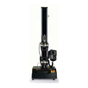
Frame base connector Base Ground stud Base adapter beam Figure 1-1. 5940 Single Column Table Frame Components The major components of an Instron electromechanical testing system include: • Load frame with integral controller • Load cell mounted to the crosshead M10-16245-EN... - Page 11 You can use non-contacting extensometers with specimens that are unable to support a contacting extensometer. Contact your regional Instron office or check our web site at www.instron.com for assistance with Instron’s grips and fixtures.
-
Page 12: Principle Of Operation
These include starting and stopping a test and using the jog controls to position the crosshead prior to installing a specimen. Software Control of the testing system is carried out via Instron Bluehill software. Setting test parameters, operating the system, and collecting test data is done through the software program. -
Page 13: System Components And Interconnections
Load cell connector Ethernet crossover Load cell cable cable System ID label Options panel Controller cover Supplemental ground cable Mains power cable Ground stud GRN/YEL - Earth BRN - Live BLU - Neutral Figure 1-2. 5940 System Connections Product Support: www.instron.com... -
Page 14: System Safety And Information Labeling
Chapter: Introduction System Safety and Information Labeling Table 1-3 on page explains the meanings of any safety and information labels that may be attached to any part of the testing system. Table 1-3. Safety and Information Labeling Descriptions Label Meaning Purpose Electrical Indicates that an electrical hazard exists... - Page 15 For advice on the disposal of electrical and electronic equipment in your country, contact your local Instron representative. Product Support: www.instron.com...
-
Page 16: Product Support
Canada, you can call directly at 1-800-473-7838. Product Documentation Instron offers a comprehensive range of documentation to help you get the most out of your Instron products. Depending on what you have purchased, your documentation may include some or all of the following: Operator’s Guide... -
Page 17: Preparing The System
Chapter 2 Preparing the System • Before you Begin ........... 2-1 •... -
Page 18: Emergency Stop Button
All grips, fixtures and accessories are free of dirt, damage and deformation. • The load frame is level. If an adjustment is necessary, refer to the System Support manual. Correct any problems before you operate the testing system. If you require assistance, contact your local Instron Service department. M10-16245-EN... -
Page 19: Control Panel
If the hourglass persists or if it is replaced with a warning icon, then the self-test has not been successful. Contact Instron Service. 4. When the system self-test has completed successfully, start the Instron Bluehill software. 5. Wait for the software to fully initialize the machine before using the jog controls on the machine. - Page 20 Chapter: Preparing the System Figure 2-3. Control Panel M10-16245-EN...
- Page 21 Press this button to move the crosshead back to the gauge length position after a test. RETURN IN PROGRESS indicator illuminates to show that the crosshead is returning to the gauge length position. Figure 2-3 on page illustrates the control panel. Table 2-1 on page describes the control panel’s functions. Product Support: www.instron.com...
-
Page 22: Bluehill Software
Chapter: Preparing the System Bluehill Software Setting test parameters, operating the system, and collecting test data is done through the software program. Home Screen Bluehill software opens at the Home screen. The console section of the software is at the top of the screen and provides important information about the system. -
Page 23: Status Bar
• Sample - the name of the current sample. • Method - the name of the current method file that is open, if any. • Report - the name of the current report template that is open. Product Support: www.instron.com... -
Page 24: Assemble The Load String
Chapter: Preparing the System • Progress messages - various messages indicating progress, for example “Opening”, “Closing” and “Generating”. Assemble the Load String The load string consists of all the hardware components between the crosshead and the base of the testing machine. It includes the load cell, the grips, the specimen and any adapters that allow you to connect all of these components together. -
Page 25: Install The Load Cell
5940 Series frames. If you have a load cell that is not listed, contact Instron for advice on compatibility and adapters that may be available for your load cell. - Page 26 Chapter: Preparing the System The crosshead is positioned below its travel midpoint so that you can easily and safely access the crosshead. The crosshead is stationary and the indicator light is not TEST IN PROGRESS illuminated. Refer to Figure 2-4 on page 2-10...
-
Page 27: Adapters
There are two types of adapters: base adapters and coupling adapters. Base Adapters Base adapters let you connect grips and fixtures to the base of the load frame. All 5940 Series load frames are supplied with a Type O base adapter installed. A Type D base adapter Product Support: www.instron.com... - Page 28 Chapter: Preparing the System is also supplied in the ancillary parts kit. If you need to remove and re-install the base adapter, for example to change the orientation, use one of the following procedures. To remove the base adapter: 1. Remove the compression spring located inside the adapter. 2.
- Page 29 Assemble the Load String Base adapter Compression spring M6 bolt Locating pins Figure 2-6. Type D Base Adapter Product Support: www.instron.com 2-13...
-
Page 30: Select Grips And Fixtures
Chapter: Preparing the System Coupling Adapters Coupling adapters let you attach grips and fixtures of different sizes to the load cell and base adapter, providing more options for testing. There are two primary types: • For tension testing only: Tension coupling adapters, also known as self-aligning coupling adapters, which provide a swivel connection and connect between clevis pin type interfaces. -
Page 31: Insert Jaw Faces Into Grips
1. For the lower grip, insert the adapter on the grip into the female clevis socket on the load frame base adapter, as shown in Figure 2-7 on page 2-16. 2. Align the clevis holes and insert the clevis pin through the holes. Product Support: www.instron.com 2-15... - Page 32 Chapter: Preparing the System 3. Secure the clevis pin in position with the clevis pin clip. 4. Repeat steps 1 through 3 to install the upper grip onto the load cell. 5. When both grips are installed, follow the procedure to preload the load string (refer to “Preload the Load String”...
-
Page 33: Preload The Load String
4. Reduce the load to zero. 5. Remove the specimen. The load string is now preloaded and all the locknuts are tight and should not move during subsequent testing. The system is now ready to test. Product Support: www.instron.com 2-17... -
Page 34: To Unload The Load String
Chapter: Preparing the System When you next need to change grips or any other part of the load string, the locknuts will be too tight to loosen by hand. Follow the unload procedure (“To unload the load string:” page 2-18). To unload the load string: 1. -
Page 35: Testing Specimens
Chapter 3 Testing Specimens • Testing a Sample........... . 3-2 •... -
Page 36: Testing A Sample
Chapter: Testing Specimens Testing a Sample The following are guidelines for the steps that you would typically go through when testing a group of specimens on a 5900 system. Some steps include references to more detail in separate sections. These guidelines assume that a test method has already been created that satisfies your testing requirements and provides the required test parameters (e.g. - Page 37 Bluehill test workspace. The test method may also include a start test parameter that may automatically start a test when specified criteria are satisfied. Review the Test Control > Start Test screen to verify how the test should start. Product Support: www.instron.com...
-
Page 38: Create A Sample In Bluehill
Chapter: Testing Specimens A test method includes the layout of the test workspace, which typically includes a graph, a results table, and an area where you can enter parameter values before or after the test. As the test proceeds you can view the graph and when the test is complete, results for that specimen display in the results table. -
Page 39: Name The New Sample
The system produces a suggested name for the sample file, based on the most recently used sample file name. If there are no sample files created, the system uses “TestSample” as the default name. The system appends a number to the file name to ensure a unique name. Product Support: www.instron.com... -
Page 40: Calibrate A Transducer
Chapter: Testing Specimens 2. In the Location field, verify the location to save the sample file. To change the location, refer to “Change the location for the sample files” below. 3. Click Next to advance to the Test tab. To return to the previous screen, click Back. Change the location for the sample files 1. -
Page 41: Manual Calibration
Set the transducer to its zero or gauge length point. b. Click OK. c. Deflect the transducer to its calibration point using a weight (load cell) or a calibration jig (extensometer). For load, if you have a load cell with an associated Product Support: www.instron.com... - Page 42 Chapter: Testing Specimens electrical calibration circuit, you can use this to apply an electrical signal instead of applying a physical force to the load cell. d. Click OK. e. Reset the transducer to its zero or gauge length point. Click OK. Non- rationalized transducers 1.
-
Page 43: Set The Zero Extension Point
1. Use the jog controls to move the crosshead to its starting position for the test. 2. Press the button on the control panel. ZERO EXTENSION On some control panels, the ZERO EXTENSION button is labeled RESET GL (reset gauge length). Product Support: www.instron.com... -
Page 44: Set The Crosshead Limit Stops
Chapter: Testing Specimens Set the crosshead limit stops Warning Crush hazard - you must set the crosshead travel limits as protection against unexpected crosshead movement. Although Bluehill lets you set limits of travel in the software, you must set the crosshead travel limits as well. -
Page 45: Move Off A Crosshead Limit Stop
Press the button to move the crosshead off the upper limit stop. Press the button to move the crosshead off the lower limit stop. The TEST IN PROGRESS indicator light illuminates when you move the crosshead. Product Support: www.instron.com 3-11... -
Page 46: Set The Limits For A Transducer
Chapter: Testing Specimens Set the limits for a transducer Warning Set the load frame limit stops to limit crosshead travel, and set adequate transducer limits to ensure the safe operation of the testing system. Set all available limits before using the system to avoid crosshead overtravel, contact between grips and fixtures, overloading any component of the load string, or overtravel of a contacting extensometer. -
Page 47: Stop A Test
Emergency Stop Button Figure 3-2. Emergency Stop Button The Emergency Stop button is a large, round, red button on the testing system. Press this button to stop the test as soon as possible when a condition develops that: Product Support: www.instron.com 3-13... -
Page 48: Crosshead Limit Switches
Chapter: Testing Specimens • Could affect the safety of persons operating the system. • Could damage the specimen, load frame, or test fixtures. Investigate and resolve the situation that caused the use of the Emergency Stop button before you reset the system. When operated, the Emergency Stop button locks into the closed position and the system is disabled until you reset the button and re-enable the load frame. -
Page 49: Troubleshooting
2. Click on the icon for the transducer that you want to work on. 3. Click the Limits tab. The label for the Enabled check box for the tripped limit changes to Tripped. 4. Click to uncheck the box. The label reverts back to Enabled. Product Support: www.instron.com 3-15... -
Page 50: A Crosshead Travel Limit Trips
Identify and resolve the condition that caused the secondary overtravel limit to trip before you use the testing system again. Contact the Instron service department for assistance. You press the Emergency Stop button Refer to “Emergency Stop Button”... - Page 51 Refer to the System Support manual for instructions on replacing a fuse. 5. When you have resolved the problem, switch on the frame and start the software program. The system should reset itself. Verify that the POWER indicator light illuminates. Product Support: www.instron.com 3-17...
- Page 52 Chapter: Testing Specimens 3-18 M10-16245-EN...
-
Page 53: Appendix A Conformance Documents
Appendix A Conformance Documents • Certificate of Conformance ......... . A-2 The copy of the certificate on the following page is a generic version. -
Page 54: Certificate Of Conformance
Name and address of the person authorised to compile the technical file: Name: Jim Rose Address: Instron Division of ITW Limited, Coronation Road, High Wycombe, Buckinghamshire, HP12 3SY, United Kingdom. Herewith declares that testing machines series T2020, 3300, 5500, 5500A, 5800, 5900... - Page 55 I n d e x Instron at GL (gauge length) ....contact information ....
- Page 56 sample file create with existing method....set zero extension point ... . specimen protect button....start new sample with existing method.
- Page 58 Product Support: www.instron.com...
Need help?
Do you have a question about the 5940 and is the answer not in the manual?
Questions and answers