Table of Contents
Advertisement
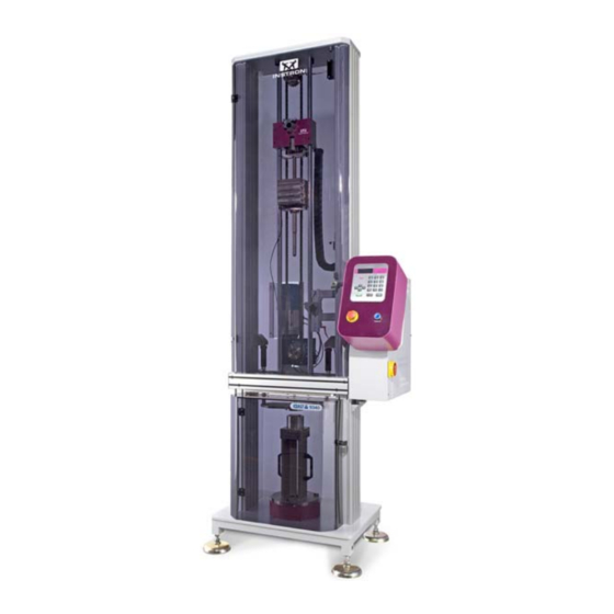
CEAST 9300 Series
Droptower Impact Systems
CEAST 9340
INSTRUCTIONS for USE
and MAINTENANCE
7510.000MN1r
ed. 1 rev. 1
The subject of this document is the exclusive property of ITW Test and Measurement Italia S.r.l. - INSTRON CEAST Division. This
document or any part thereof must not be reproduced in any form, nor information contained therein disclosed to third parties nor
methods, procedures or test described therein performed, without the written permision of ITW Test and Measurement Italia S.r.l.
- INSTRON CEAST Division.
Advertisement
Table of Contents

Related Manuals for Instron CEAST 9340


Summary of Contents for Instron CEAST 9340
- Page 1 1 rev. 1 The subject of this document is the exclusive property of ITW Test and Measurement Italia S.r.l. - INSTRON CEAST Division. This document or any part thereof must not be reproduced in any form, nor information contained therein disclosed to third parties nor methods, procedures or test described therein performed, without the written permision of ITW Test and Measurement Italia S.r.l.
-
Page 2: Table Of Contents
6.6 MATERIALS AND PRODUCTS ......................33 7. START-UP ..........................34 7.1 INSTRUMENT, CEAST DAS 8000 JUNIOR/CEAST 16000 AND PC CONNECTION ....... 34 7.2 ELECTRICAL SERVICE CONNECTION ................... 34 Page 2 - CEAST 9340 - Instructions for Use and Maintenance 7510.000MN1r ed. 1 rev. 1... - Page 3 8.8 SUPPORT STANDS CODES 7520.350 AND 7520.351 FOR PLATES OF FIBER REINFORCED POLYMERS ............................98 8.8.1 INTRODUCTION ..............................98 8.8.2 COMPONENTS IDENTIFICATION ........................98 Page 3 CEAST 9340 - Instructions for Use and Maintenance 7510.000MN1r ed. 1 rev. 1 -...
- Page 4 APPENDIX C - TOOLING FOR TENSILE IMPACT TEST ONLY ........... 160 APPENDIX D - STRIKERS TECHNICAL FEATURES ............161 APPENDIX E - INPUT LIST ..................... 165 APPENDIX F - OUTPUT LIST ....................167 Page 4 - CEAST 9340 - Instructions for Use and Maintenance 7510.000MN1r ed. 1 rev. 1...
- Page 5 APPENDIX G - ERROR CODES LIST ..................169 APPENDIX H - STRIKER ANTIREBOUND SYSTEM ............. 178 Page 5 CEAST 9340 - Instructions for Use and Maintenance 7510.000MN1r ed. 1 rev. 1 -...
- Page 6 PRINT DATE: MARCH 02, 2010 REVISION TOPIC: - Changed the legal name of the firm from "Instron" to "ITW Test and Instrument Italia S.r.l. - INSTRON CEAST Division" where necessary. - Appendix G: changed “Instron Service” with “Authorized Service” in the tables of Error Codes Lists, pages 168, 172, 173 and 174.
-
Page 7: Legend
Additional information, observations, explanations and recommendations. Potential danger of extremely risky situation for life or health . Beware of potential danger to the operator and/or risk of equipment damage. Page 7 CEAST 9340 - Instructions for Use and Maintenance 7510.000MN1r ed. 1 rev. 1 -... -
Page 8: General Information
“Maintenance Personnel, qualified or trained” after dis- connecting the instrument from the electrical service and removing the plug from the electrical socket. Page 8 - CEAST 9340 - Instructions for Use and Maintenance 7510.000MN1r ed. 1 rev. 1... - Page 9 The room in which the nitrogen is used must be well ventilated to avoid envi- ronment saturation problems (lowering of the oxygen percentage) with a risk of suffocation. Page 9 CEAST 9340 - Instructions for Use and Maintenance 7510.000MN1r ed. 1 rev. 1 -...
- Page 10 Local exhaust system of 1200 m /hour is recommended to prevent high nitrogen concentration when use the CEAST 9340 equipped with the environmental chamber. Page 10 - CEAST 9340 - Instructions for Use and Maintenance 7510.000MN1r ed. 1 rev. 1...
-
Page 11: Equipment Description
1.1.3 DIFFERENCE BETWEEN INSTRUMENTS • • • • • CEAST 9340 code 7515.000: it is equipped with a standard chamber for tests at ambient temperature; • • • • • CEAST 9340 code 7516.000: it is equipped with an environmental chamber for speci- mens conditioning at temperatures: - 50 °C to 100 °C. - Page 12 The instrument memory is able to store up to 25 sets of test parameters. Page 12 - CEAST 9340 - Instructions for Use and Maintenance 7510.000MN1r ed. 1 rev. 1...
-
Page 13: Options
Max. specimen thickness 195 mm Note: the table above summarises only the main options. Many other options are avail- able such as: strikers, specimens supports, adapters, etc.. Page 13 CEAST 9340 - Instructions for Use and Maintenance 7510.000MN1r ed. 1 rev. 1 -... -
Page 14: Technical Characteristics
4 °C / minute Impact and rebound velocity measured by optical detector Striker position measured by digital encoder Specimen clamping on support by clamping device, pneumatically actuated Page 14 - CEAST 9340 - Instructions for Use and Maintenance 7510.000MN1r ed. 1 rev. 1... - Page 15 490 x 450 x 565 370 x 300 x 495 Connection see 1.2.1 Layout drawing Weight Instrument [kg] Paint Grey RAL 7035 - Fuchsia RAL 4006 Page 15 CEAST 9340 - Instructions for Use and Maintenance 7510.000MN1r ed. 1 rev. 1 -...
-
Page 16: Layout
1.2.1 LAYOUT Page 16 - CEAST 9340 - Instructions for Use and Maintenance 7510.000MN1r ed. 1 rev. 1... -
Page 17: Safety
• • • • • This manual must always be accessible, so that it can be consulted in case of doubts about the correct conditions of use of the instrument. Page 17 CEAST 9340 - Instructions for Use and Maintenance 7510.000MN1r ed. 1 rev. 1 -... -
Page 18: Conditions Of Use
OPERATOR The Operator of the CEAST 9340 must have a specific qualification from a recognized school for analogous apparatus, or under the guidance of expert personnel. The opera- tor can perform only the operations indicated and specified in this manual, following the instructions herein. -
Page 19: Normal Use Conditions
After 20,000 hours of work, and in any case not longer than 10 years, a complete over- haul of the apparatus by ITW Test and Instrument Italia S.r.l. - INSTRON CEAST Divi- sion is necessary in order to continue to use it safely. The cost of overhaul are the responsibility of the CUSTOMER. -
Page 20: Abnormal Situations
The instrument must not be installed or operated in a corrosive or explosive environment. Do not wash the instrument with water jets or flammable materials (e.g.: diesel fuel, gasoline, solvents, etc.). Page 20 - CEAST 9340 - Instructions for Use and Maintenance 7510.000MN1r ed. 1 rev. 1... -
Page 21: Operator Work Station
Operator at work station Page 21 CEAST 9340 - Instructions for Use and Maintenance 7510.000MN1r ed. 1 rev. 1 -... -
Page 22: Transport And Movement
When the instrument is in vertical position, use always the four eyebolts (on the upper part of the turret) to lift and move it in the laboratory. During movement of the instrument, proceed slowly Page 22 - CEAST 9340 - Instructions for Use and Maintenance 7510.000MN1r ed. 1 rev. 1... -
Page 23: Weight Of The Main Parts
If the instrument or accessories should be damaged or missing, it is imperative to not continue with the installation, but to notify ITW Test and Instrument Italia S.r.l. - INSTRON CEAST Division immediately via fax of the anomaly found, and to agree with the former the action to be taken. -
Page 24: Mounting And Dismantling
Should the USER need to dismantle one or more parts for which the procedure is not included in this manual, it is imperative that ITW Test and Instrument Italia S.r.l. - INSTRON CEAST Division be contacted for authorization and the procedure. -
Page 25: Installation
ID plate of the instrument (see chapter 1) and a pneu- matic air supply line (see paragraph 1.2) able to delivery compressed air with pressure 7 to 10 bar. Page 25 CEAST 9340 - Instructions for Use and Maintenance 7510.000MN1r ed. 1 rev. 1 -... -
Page 26: Positioning
1.5 kg/cm (15 N/cm ) at the location of each foot. Standard foot (x 4) Front side Page 26 - CEAST 9340 - Instructions for Use and Maintenance 7510.000MN1r ed. 1 rev. 1... -
Page 27: Load On Slab
(load calculated for tests in the worse condition ment is placed must be able using materials very tough) to hold at least 2000 kg/m (20000 N/m Page 27 CEAST 9340 - Instructions for Use and Maintenance 7510.000MN1r ed. 1 rev. 1 -... -
Page 28: Installation Procedure
Remove the screws (x 6) and brackets (x 6) fastening the instrument to the pallet (Fig. 1 and detail). Bracket (x 6) Screw (x 6) Fig. 1 Page 28 - CEAST 9340 - Instructions for Use and Maintenance 7510.000MN1r ed. 1 rev. 1... - Page 29 Reeve the ropes through the four eyebolts as shown (arrows) in the details of Fig. 2. e) Place the ropes on the forks of two forklifts or bridge cranes. Fig. 2 Page 29 CEAST 9340 - Instructions for Use and Maintenance 7510.000MN1r ed. 1 rev. 1 -...
- Page 30 (take care do not damage the feets during this operation) and then with all four feet (vertical position). Fig. 3 Fig. 4 Page 30 - CEAST 9340 - Instructions for Use and Maintenance 7510.000MN1r ed. 1 rev. 1...
- Page 31 When the instrument is in vertical position, use always the four eyebolts (on the upper part of the turret) to lift and move it in the laboratory. Fig. 5 Fig. 6 Page 31 CEAST 9340 - Instructions for Use and Maintenance 7510.000MN1r ed. 1 rev. 1 -...
-
Page 32: Levelling
Once levelled, check that the four feet are in contact with the floor. Spirit level (longitudinal position) Spirit level (transversal position) Crosshead guide column Fig. 1 Fig. 2 Page 32 - CEAST 9340 - Instructions for Use and Maintenance 7510.000MN1r ed. 1 rev. 1... -
Page 33: Stability
The disposal of the materials must be done by the CUSTOMER, according to the local environmental laws of the COUNTRY in which the instrument is located. Don’t Litter. Recycle. Page 33 CEAST 9340 - Instructions for Use and Maintenance 7510.000MN1r ed. 1 rev. 1 -... -
Page 34: Start-Up
Insert plug of power cord into the laboratory mains outlet and close mains safety switch (wall mounted). Power cord Main switch with plug Page 34 - CEAST 9340 - Instructions for Use and Maintenance 7510.000MN1r ed. 1 rev. 1... -
Page 35: Pneumatic Service Connection
Pressure regulator Slot for padlock (knob) ON/OFF valve (knob) Pressure gauge (pressure to be set at 5 bar) Compressed air inlet (press. 10 bar max.) Page 35 CEAST 9340 - Instructions for Use and Maintenance 7510.000MN1r ed. 1 rev. 1 -... -
Page 36: Cryogenic Service Connection
Local exhaust system of 1200 m /hour is recommended to prevent high nitrogen concentration when use the CEAST 9340 equipped with the environmental chamber. Page 36 - CEAST 9340 - Instructions for Use and Maintenance 7510.000MN1r ed. 1 rev. 1... - Page 37 Connect the nitrogen tank to the pipe fitting of the CEAST 9340 using the flexible hose provided with the tank or connect the CEAST 9340 to the nitrogen line of the laboratory. The delivery pressure must be set between 1.2 and 1.5 bar.
-
Page 38: Use
. For safety reasons, it is forbiden to change or modify any part or portion of the instrument Page 38 - CEAST 9340 - Instructions for Use and Maintenance 7510.000MN1r ed. 1 rev. 1... -
Page 39: Component Identification
Turret Control Environmental test chamber Test chamber Fig. 1 - CEAST 9340 7515.000. Fig. 2 - CEAST 9340 7516.000. General view General view Page 39 CEAST 9340 - Instructions for Use and Maintenance 7510.000MN1r ed. 1 rev. 1 -... - Page 40 (Optical detector for energy absorbers) impact and rebound velocity measuring system) Absorber block (x 2) Striker antirebound system (option) Fig. 3 - View inside turret Page 40 - CEAST 9340 - Instructions for Use and Maintenance 7510.000MN1r ed. 1 rev. 1...
-
Page 41: Safeties And Their Locations
When you close the door: • After a few seconds all systems inside the turret and the environmental chamber are enabled and the previous operating conditions are restored. Page 41 CEAST 9340 - Instructions for Use and Maintenance 7510.000MN1r ed. 1 rev. 1 -... - Page 42 7) - Pressure switch: it intervene and cut off the power to the instrument when the pressure of the compressed air goes down below 5 bar. Page 42 - CEAST 9340 - Instructions for Use and Maintenance 7510.000MN1r ed. 1 rev. 1...
-
Page 43: Commands
The large liquid crystal display allows up to 80 characters to be shown on 4 rows. Page 43 CEAST 9340 - Instructions for Use and Maintenance 7510.000MN1r ed. 1 rev. 1 -... -
Page 44: Operations
To enter a letter of the alphabet you must continue to press the key with the corresponding letter until it is shown in the display (the same method used by mobile phones). Page 44 - CEAST 9340 - Instructions for Use and Maintenance 7510.000MN1r ed. 1 rev. 1... -
Page 45: Program
Vid. (Screen) and a progressive number, XXX, that follows the order of appear- ance on the screen of the display. This order is followed in order to present the figures during the description of the program. Page 45 CEAST 9340 - Instructions for Use and Maintenance 7510.000MN1r ed. 1 rev. 1 -... - Page 46 Menus used by Service Personnel of ITW Test Parameters Vid. 1.7 Vid. 1.7.7 and Measurement Italia S.r.l. - INSTRON CEAST Division only Representation of the program structure (firmware) in hierarchical order Page 46 - CEAST 9340 - Instructions for Use and Maintenance 7510.000MN1r ed. 1 rev. 1...
-
Page 47: Program Start - Up
START for CEAST 9340 startup CEAST 9340 startup CEAST 9340 startup CEAST 9340 startup CEAST 9340 startup Vid. 00 - CEAST 9340 Startup Screen Page 47 CEAST 9340 - Instructions for Use and Maintenance 7510.000MN1r ed. 1 rev. 1 -... -
Page 48: Navigation Through The Program Menus
Note: - The numbers shown next to the figures are used as explicit references in order to facilitate the comprehension of the text, but do not appear on the display. Page 48 - CEAST 9340 - Instructions for Use and Maintenance 7510.000MN1r ed. 1 rev. 1... - Page 49 - Press the key and release it: to exit from the active screen and return to the preceding one; - Press the key and maintain it pressed: to exit from the active screen and return to the first screen (main menu). Page 49 CEAST 9340 - Instructions for Use and Maintenance 7510.000MN1r ed. 1 rev. 1 -...
-
Page 50: Main Menu
Each function is selectable with the cursor “>” using the keys and confirmed with the key. ENTER Rule Photocell (Optical Detector) Knob Photocell height adjusting device (ref. step 3) Page 50 - CEAST 9340 - Instructions for Use and Maintenance 7510.000MN1r ed. 1 rev. 1... -
Page 51: Set Temperature
“Current ENTER Parameters” and the program returns automatically to the main menu (Vid. 1). Page 51 CEAST 9340 - Instructions for Use and Maintenance 7510.000MN1r ed. 1 rev. 1 -... -
Page 52: Modify Parameters
This is the suggested condition for tests at low temperature on films. When the environmental chamber door is open for the specimen replacement, the systems inside the chamber are switched-off. Page 52 - CEAST 9340 - Instructions for Use and Maintenance 7510.000MN1r ed. 1 rev. 1... - Page 53 6) “Antirebound”: it enables (Y) or disables (N) the striker antirebound system (if in- stalled and configured in the program). 7) “Other param.”: it goes to the next menu of parameters (see Vid. 1.3 b). Page 53 CEAST 9340 - Instructions for Use and Maintenance 7510.000MN1r ed. 1 rev. 1 -...
- Page 54 16) “Impact Offset”: is the distance between the nominal impact plane and the speci- men surface. Parameter shown only if the “Support Type” parameter (see Vid. 1.3 a) is selected “V”. Page 54 - CEAST 9340 - Instructions for Use and Maintenance 7510.000MN1r ed. 1 rev. 1...
- Page 55 [mm] - 120 + 100 +/-xx Note: for further technical data related to the “striker antirebound system” make refer- ence to the “Appendix H“. Page 55 CEAST 9340 - Instructions for Use and Maintenance 7510.000MN1r ed. 1 rev. 1 -...
-
Page 56: Save Parameters
6) “xx.x m/s”: it is the expected velocity. 7) “M: xx.x kg”: it is the dropping mass. 8) “E: xxxx J”: it is the potential energy. Page 56 - CEAST 9340 - Instructions for Use and Maintenance 7510.000MN1r ed. 1 rev. 1... -
Page 57: Utility
4) “Modify Password”: to modify the password set for the “User” level. 5) “Clock”: function for setting the time and date. 6) “Language”: select the language preferred by the user. Page 57 CEAST 9340 - Instructions for Use and Maintenance 7510.000MN1r ed. 1 rev. 1 -... -
Page 58: Input Password
“User” level. If you want to restart as “Operator” level instead the “User” one, you must change it before to switch the instrument off. Page 58 - CEAST 9340 - Instructions for Use and Maintenance 7510.000MN1r ed. 1 rev. 1... -
Page 59: Cycle Counter
4) “CONF. 8 - 1”: configuration of the instrument: “A” Environmental Chamber “B” Striker Antirebound System Note: bit value: 1 installed; 0 not installed. Page 59 CEAST 9340 - Instructions for Use and Maintenance 7510.000MN1r ed. 1 rev. 1 -... -
Page 60: Modify Password
Function used to see the actual clock value and to modify the time and date. After the modification select the function “Apply” and confirm it using the key to ENTER make the change operative. Page 60 - CEAST 9340 - Instructions for Use and Maintenance 7510.000MN1r ed. 1 rev. 1... -
Page 61: Language
Test and Measurement Italia S.r.l. - INSTRON CEAST Division personnel for setup and Service. Press the key to return to the previous screen. BACK Page 61 CEAST 9340 - Instructions for Use and Maintenance 7510.000MN1r ed. 1 rev. 1 -... -
Page 62: Shutter Moving
Vid. 1.7.2 - “Striker Release“ Press the “START” key to release the striker or the “BACK” key to return to the previous screen without release the striker. Page 62 - CEAST 9340 - Instructions for Use and Maintenance 7510.000MN1r ed. 1 rev. 1... -
Page 63: Move To Height
1) Absolute crosshead height [mm]; 2) Temperature set [°C] (*); 3) Temperature measured [°C] in the environmental chamber (*). (*): only with environmental chamber. Page 63 CEAST 9340 - Instructions for Use and Maintenance 7510.000MN1r ed. 1 rev. 1 -... -
Page 64: Visualize I/O
8.5.22 ERROR CODES IN THE PROGRAM Error codes are shown on display and advise the user when an error occurs, see the Error Codes List in the Appendix G. Page 64 - CEAST 9340 - Instructions for Use and Maintenance 7510.000MN1r ed. 1 rev. 1... -
Page 65: Preparing The Instrument For Testing
8.6.1 REPLACEMENT OF THE STANDS Authorized Personnel: Operator Note: stands for CEAST 9340 are mainly of two different types as shown in the figures below. The stands (Fig. 1 and 2) can be installed indiferrently both in the standard (ambient temperature) chamber and in the environmental one. -
Page 66: Replacement Of The Specimen Fixtures
Place and visually center the speci- men onto the specimen fixture on top of the fixed height stand. Page 66 - CEAST 9340 - Instructions for Use and Maintenance 7510.000MN1r ed. 1 rev. 1... - Page 67 Adjustable block Screw Fig. 1 C - Shoulder Fig. 1 - Fixture for Charpy test with shoulders according to ASTM standards (notched plastic specimen) Page 67 CEAST 9340 - Instructions for Use and Maintenance 7510.000MN1r ed. 1 rev. 1 -...
- Page 68 Fig. 3 B - Unnotched specimen Fig. 3 - Fixture for Charpy test with shoulders according to ISO standards (notched and unnotched plastic specimens) Page 68 - CEAST 9340 - Instructions for Use and Maintenance 7510.000MN1r ed. 1 rev. 1...
- Page 69 (fig. 1 A) or against the alignment pins (fig. 2 or 3 A). Push the notch centering pin forward and center the notch. For unnotched specimen use the stop plate. Page 69 CEAST 9340 - Instructions for Use and Maintenance 7510.000MN1r ed. 1 rev. 1 -...
- Page 70 Clamp the specimen with the clamping screw. Page 70 - CEAST 9340 - Instructions for Use and Maintenance 7510.000MN1r ed. 1 rev. 1...
- Page 71 Place the fixtures adapter on top of the adjustable height stand and en- gage the pin in the underlying hole. c) Tighten the screw. Adjustable height stand Page 71 CEAST 9340 - Instructions for Use and Maintenance 7510.000MN1r ed. 1 rev. 1 -...
- Page 72 X = Striker height [mm] - 134 [mm] + Impact offset [mm]; where: “Striker height” = 239 to 370 [mm]; “Impact offset” = -120 to 100 [mm]. Page 72 - CEAST 9340 - Instructions for Use and Maintenance 7510.000MN1r ed. 1 rev. 1...
- Page 73 Adjust the height of the stand until the specimen surface touches the striker end. k) Lock the stand using the locking handles. l) Press the “Home” key to move the striker at the rest position. Page 73 CEAST 9340 - Instructions for Use and Maintenance 7510.000MN1r ed. 1 rev. 1 -...
-
Page 74: Replacement Of The Striker Holder
Remove the striker holder from the guide columns of the instrument and place it on a table. Page 74 - CEAST 9340 - Instructions for Use and Maintenance 7510.000MN1r ed. 1 rev. 1... - Page 75 - Close the door of the turret; - Press the “Power ON” button; - Press the “Home” key and wait the automatic recovery and repositioning of the striker holder. Page 75 CEAST 9340 - Instructions for Use and Maintenance 7510.000MN1r ed. 1 rev. 1 -...
-
Page 76: Replacement Of The Weights
(for masses 1 to 3.5 kg, striker not included) Fig. 3 Fig. 4 Combinable weight for Combinable weight for standard striker holder light striker holder Page 76 - CEAST 9340 - Instructions for Use and Maintenance 7510.000MN1r ed. 1 rev. 1... - Page 77 Place the second part of the weight on the first one and fasten it with screw; - Install the remaining two weights if necessary. Page 77 CEAST 9340 - Instructions for Use and Maintenance 7510.000MN1r ed. 1 rev. 1 -...
-
Page 78: Replacement Of Striker
Remove the striker from the striker holder. Signal cable holder Connector Signal cable Instrumented striker Fig. 1 - Instrumented striker (usable with both striker holder) Page 78 - CEAST 9340 - Instructions for Use and Maintenance 7510.000MN1r ed. 1 rev. 1... - Page 79 Screw (x2) Detail Detail Detail Signal cable to the DAS Instrumented Data Acquisition System Striker Fig. 2 - Instrumented striker installed on the instrument Page 79 CEAST 9340 - Instructions for Use and Maintenance 7510.000MN1r ed. 1 rev. 1 -...
- Page 80 - Check that the striker signal cable is far enough from the cylinder (on the left side of turret) of antirebound system avoiding to cut the cable during the movement of the antirebound crosshead or during the striker repositioning. Page 80 - CEAST 9340 - Instructions for Use and Maintenance 7510.000MN1r ed. 1 rev. 1...
-
Page 81: Replacement Of The Striker Extension
Note:- The addition of the striker extension can cause interference between the striker head and the special-purpose tooling installed on the adjustable height stand. Page 81 CEAST 9340 - Instructions for Use and Maintenance 7510.000MN1r ed. 1 rev. 1 -... -
Page 82: Replacement Of The Striker's Heads (Interchangeable Head Type)
(optional device) Fig. 3 - Striker with Charpy head installed Fig. 4 - Striker with Izod head installed on CEAST 9340 on CEAST 9340 Page 82 - CEAST 9340 - Instructions for Use and Maintenance 7510.000MN1r ed. 1 rev. 1... - Page 83 (Fig. 7). On the contrary, leave it in place for 20 mm O.D. head. 2) Screw the head to the striker body end by hand. Page 83 CEAST 9340 - Instructions for Use and Maintenance 7510.000MN1r ed. 1 rev. 1 -...
- Page 84 6) Hold the Charpy head in position and tighten the ring nut. Ring nut Charpy head Spacer Heads alignment template Fig. 8 - Striker with the Charpy head aligned Page 84 - CEAST 9340 - Instructions for Use and Maintenance 7510.000MN1r ed. 1 rev. 1...
- Page 85 5) Hold the Izod head in position and tighten the ring nut. Ring nut Izod head Spacer Heads alignment template Fig. 9 - Striker with the Izod head aligned Page 85 CEAST 9340 - Instructions for Use and Maintenance 7510.000MN1r ed. 1 rev. 1 -...
-
Page 86: Preparing The Instrument For Tensile-Impact Test Only
Note: before installing the equipment for the “Tensile-Impact tests”, remove the clamp- ing plate from the chamber as shown in the figure below. Clamping plate installed in the chamber Shoulder Shoulder screw screw Page 86 - CEAST 9340 - Instructions for Use and Maintenance 7510.000MN1r ed. 1 rev. 1... - Page 87 (Data Acquisi- chamber wall) tion System) Screw Notched Slot for (x 2) washer cable (x 2) Fig. 1 - Instrument configured for Tensile-Impact test. Page 87 CEAST 9340 - Instructions for Use and Maintenance 7510.000MN1r ed. 1 rev. 1 -...
-
Page 88: Replacement Of The Fixed Height Vice Support Stand
Rubber plate Position of collecting box during tests Signal cable Fig. 2 - Fixed height vice support stand Page 88 - CEAST 9340 - Instructions for Use and Maintenance 7510.000MN1r ed. 1 rev. 1... - Page 89 Place the collecting box onto the base of the vice support stand (Fig. 2). Page 89 CEAST 9340 - Instructions for Use and Maintenance 7510.000MN1r ed. 1 rev. 1 -...
-
Page 90: Replacement Of The Piezoelectric Force Sensor
17 mm (upper part) open wrench Signal cable (supplied) connector Piezoelectric force sensor Sliding stop plate Fig. 2 - Piezoelectric force sensor assembly Page 90 - CEAST 9340 - Instructions for Use and Maintenance 7510.000MN1r ed. 1 rev. 1... - Page 91 Tighten the force sensor using the open wrench (Fig. 2B). g) Pass the signal cable inside the clamps and fasten them with screws. Page 91 CEAST 9340 - Instructions for Use and Maintenance 7510.000MN1r ed. 1 rev. 1 -...
-
Page 92: Replacement Of The Instrumented Vice For Tensile-Impact
Remove the screws E (x4) and remove the adapter C from downward. c) Remove the plate B. Sliding stop plate Page 92 - CEAST 9340 - Instructions for Use and Maintenance 7510.000MN1r ed. 1 rev. 1... - Page 93 Exagonal key c) Insert the plate B in the adapter A checking that the knurled surface is turned toward the arrow. Page 93 CEAST 9340 - Instructions for Use and Maintenance 7510.000MN1r ed. 1 rev. 1 -...
- Page 94 Position for Sliding Springing Position for specimens stop plate ball (2 for specimens type 2 and 4 each side) type 1, 3 and 5 Page 94 - CEAST 9340 - Instructions for Use and Maintenance 7510.000MN1r ed. 1 rev. 1...
-
Page 95: Replacement Of The Tensile-Impact Specimen
(see Fig. 2, para 8.7.2). Clamping screw (x2) c) Loosen the screws and remove the broken specimen. Calibrated free tensile grip Page 95 CEAST 9340 - Instructions for Use and Maintenance 7510.000MN1r ed. 1 rev. 1 -... - Page 96 Check that the calibrated free tensile grip is visually centered with the stop plates. Clamping screw m) Tighten the clamping screw. Specimen Sliding stop plate Calibrated free tensile grip Page 96 - CEAST 9340 - Instructions for Use and Maintenance 7510.000MN1r ed. 1 rev. 1...
-
Page 97: Replacement Of Striker For Tensile-Impact Tests
Place the striker against the striker holder centering the existing pins and making sure that the plate is turned toward the front of instrument. c) Fasten the striker with screws. Page 97 CEAST 9340 - Instructions for Use and Maintenance 7510.000MN1r ed. 1 rev. 1 -... -
Page 98: Support Stands Codes 7520.350 And 7520.351 For Plates Of Fiber Reinforced Polymers
Pin (x 3) for Specimen size for Specimen size for code 7520.350 code 7520.351 specimen position (plate 100 x 150 mm) (plate 4 x 6”) Page 98 - CEAST 9340 - Instructions for Use and Maintenance 7510.000MN1r ed. 1 rev. 1... -
Page 99: Disassembly And Assembly Of The Support Stands
Support Stand code 7520.350 / 7520.351 installed in the test chamber of CEAST 9340 8.8.3 DISASSEMBLY AND ASSEMBLY OF THE SUPPORT STANDS For disassembly/assembly of the support stands see the instructions of para. 8.6.1”Re- placement of the Stand”. -
Page 100: Special-Purpose Tooling For Impact Tests On Pipes
Fig. 2 - Pipe Support 90° code 7520.210 according to ASTM D-2444 standard for pipes diameter 25 to 65 mm (to be used together with the adjustable height support code 7520.035) Page 100 - CEAST 9340 - Instructions for Use and Maintenance 7510.000MN1r ed. 1 rev. 1... - Page 101 Lift manually the spring eyelet, disengage the lock bar from the bracket slot and disengage the tube or the fitting from the lock bar. Page 101 CEAST 9340 - Instructions for Use and Maintenance 7510.000MN1r ed. 1 rev. 1 -...
-
Page 102: Special Heads For Striker
Note:- For the heads assembling refer to the Appendix B- Assembly flow chart for interchangeable head strikers and to the Chapter 8.6.7 Replacement of the striker’s heads. Page 102 - CEAST 9340 - Instructions for Use and Maintenance 7510.000MN1r ed. 1 rev. 1... -
Page 103: Carry Out Test
4) Bring the instrument at HOME position using the proper key. 5) Carry out test. Page 103 CEAST 9340 - Instructions for Use and Maintenance 7510.000MN1r ed. 1 rev. 1 -... -
Page 104: Screens Shown During Test
(same height in case of high velocity). The field “xx C” shows the temperature (only if the environmental chamber is config- ured and the conditioning is activated. Page 104 - CEAST 9340 - Instructions for Use and Maintenance 7510.000MN1r ed. 1 rev. 1... -
Page 105: Test End
3) Press the BACK key to exit from this screen. Note:- Values related to the last test performed can be recalled with the “Results” function (see para. 8.5.7). Page 105 CEAST 9340 - Instructions for Use and Maintenance 7510.000MN1r ed. 1 rev. 1 -... -
Page 106: Maintenance
Any work method that compromises the safety of the apparatus must be avoided. For safety reasons, arbitrary changes or adaptations of the instrument are prohibited Page 106 - CEAST 9340 - Instructions for Use and Maintenance 7510.000MN1r ed. 1 rev. 1... -
Page 107: Fuses Replacement
Fuses to be used as spare parts: CEAST code 0201.183 Quick Fuse 10A Code ITW1421010 (x2) CEAST code 0201.184 Quick Fuse Omega 16A Code GL138316 (x2) Page 107 CEAST 9340 - Instructions for Use and Maintenance 7510.000MN1r ed. 1 rev. 1 -... - Page 108 CEAST code 0200.850 Quick Fuse 5 x 20 1.5A CEAST code 0200.855 Fuse 5 x 20 0.5A CEAST code 0201.184 Quick Fuse Omega 16A Code GL138316 Page 108 - CEAST 9340 - Instructions for Use and Maintenance 7510.000MN1r ed. 1 rev. 1...
-
Page 109: Cleaning And Drying Methods
The purpose of above-mentioned operations is to eliminate condensate from the environmental chamber and to avoid the formation of rust. Page 109 CEAST 9340 - Instructions for Use and Maintenance 7510.000MN1r ed. 1 rev. 1 -... -
Page 110: Procedure For Loading Firmware Updates
Copy the folder HC 12 Loader (sent by e-mail from ITW Test and Measurement Italia S.r.l. - INSTRON CEAST Division) on the PC (C:\, Desktop ... ) or on a floppy disk. c) Open the folder and verify the completeness of the folder content: - five files (complete updating, Loader and FW) see Fig. - Page 111 Function used to access loading program the loading window To close the FW loading program Fig. 2 e) Activate the Setting configuration menu (Fig. 2). Page 111 CEAST 9340 - Instructions for Use and Maintenance 7510.000MN1r ed. 1 rev. 1 -...
- Page 112 Note: do not modify any other fields shown in the window of Fig. 3 f) Select the serial port chosen for transfer. Confirm the configuration using the OK button. Page 112 - CEAST 9340 - Instructions for Use and Maintenance 7510.000MN1r ed. 1 rev. 1...
-
Page 113: Loading
2. Loading of the Loader version (file Loader X_X.SX) (**) 3. Loading of the FW update (file FW X-XX.SX) (**) In case of the firmware update only, do not perform these operations. Page 113 CEAST 9340 - Instructions for Use and Maintenance 7510.000MN1r ed. 1 rev. 1 -... -
Page 114: Loader Upgrade
Switch-on the instrument and wait until the loading procedure ends. When the op- eration ends the program visualizes the transfer results in the “Status” field: (Transfer Failed / End of File). Page 114 - CEAST 9340 - Instructions for Use and Maintenance 7510.000MN1r ed. 1 rev. 1... -
Page 115: Disconnection
Par.> and compare all the calibration parameters with those previously noted in the notebook (see Note, para. 9.4.2). c) If the display do not visualizes an error status, proceed with the use of the instrument. Page 115 CEAST 9340 - Instructions for Use and Maintenance 7510.000MN1r ed. 1 rev. 1 -... -
Page 116: Replacement Of The Impact Rollers
Replace the impact rollers with a new ones, code 7510.AF.07. e) Position the new rollers and fasten them with the retaining rings. Impact roller (x2) Retaining ring (x2) Impact roller Retaining ring Page 116 - CEAST 9340 - Instructions for Use and Maintenance 7510.000MN1r ed. 1 rev. 1... -
Page 117: Greasing The Striker Releasing Mechanism
Visually check the lubrication condition of the striker releasing mechanism. If necessary smear the mechanism (see the arrows) with grease type AREXONS GC 300. c) Close the turret door. Points to be greased Page 117 CEAST 9340 - Instructions for Use and Maintenance 7510.000MN1r ed. 1 rev. 1 -... -
Page 118: Lubricating The Gearing Chain
Visually check the lubrication condition of the gearing chain. If necessary smear the chain with protective oil, type AREXONS TO 236. c) Close the turret door. Gearing chain Page 118 - CEAST 9340 - Instructions for Use and Maintenance 7510.000MN1r ed. 1 rev. 1... -
Page 119: Verifying The Gearing Chain Tightening
Proceed with the instructions of steps d), e) and f) until to measure the correct deflection. Gearing chain Direction of the force applied on the chain by dynamometer Dynamometer Ratiomotor Screw (x4) Page 119 CEAST 9340 - Instructions for Use and Maintenance 7510.000MN1r ed. 1 rev. 1 -... -
Page 120: Spare Parts
10.1.1 CEAST 9340 7515.000 AND 7516.000 Code Description Q.ty 0303.028 External retaining ring 12 UNI 7434-75 7510.AF.07 Impact Roller Page 120 - CEAST 9340 - Instructions for Use and Maintenance 7510.000MN1r ed. 1 rev. 1... -
Page 121: List Of Spare Parts For Technical Assistance
7510.AG.20 Photocell with connector 7510.AH.05 Motor pinion gear 7510.AH.06 Upper pinion gear 7510.CA.04 Guiding plate for standard striker holder 7510.CB.03 Guiding plate for light striker holder Page 121 CEAST 9340 - Instructions for Use and Maintenance 7510.000MN1r ed. 1 rev. 1 -... - Page 122 2 pieces (*) Part fastened on the turret door Page 122 - CEAST 9340 - Instructions for Use and Maintenance 7510.000MN1r ed. 1 rev. 1...
- Page 123 Page 123 CEAST 9340 - Instructions for Use and Maintenance 7510.000MN1r ed. 1 rev. 1 -...
-
Page 124: Environmental Chamber 7510.011
Temperature sensor, Pt 100 GEFRAN 0400.799 Clamp with rubber lever SOU C7-10 0500.666 Solenoid valve SCE 263 B206 LT 24V/50H 0800.808 Sensor clamp 1260.16.F 0800.957 Sensor RS.UAC.1 PNEUMAX Page 124 - CEAST 9340 - Instructions for Use and Maintenance 7510.000MN1r ed. 1 rev. 1... -
Page 125: Striker Antirebound System Code 7510.002
10.2.3 STRIKER ANTIREBOUND SYSTEM CODE 7510.002 (OPTIONAL EXTRA FOR CEAST 9340 7515.000 AND 7516.000) Code Description 0801.620 Sensor 1500.U PNEUMAX with LED and cable 7520.EB.04 Shock absorber Page 125 CEAST 9340 - Instructions for Use and Maintenance 7510.000MN1r ed. 1 rev. 1 -... -
Page 126: Training
Every person who will operate with the instrument must be authorized by the Safety Manager and must read the contents of this manual. Page 126 - CEAST 9340 - Instructions for Use and Maintenance 7510.000MN1r ed. 1 rev. 1... -
Page 127: Wiring Diagrams
Lista Localizzazioni (Location List) 17 of 20 9340 Wire List 18 of 20 9340 Wire List 19 of 20 9340 Wire List 20 of 20 Page 127 CEAST 9340 - Instructions for Use and Maintenance 7510.000MN1r ed. 1 rev. 1 -... - Page 128 Page 128 - CEAST 9340 - Instructions for Use and Maintenance 7510.000MN1r ed. 1 rev. 1...
- Page 129 +12V -12V Page 129 CEAST 9340 - Instructions for Use and Maintenance 7510.000MN1r ed. 1 rev. 1 -...
- Page 130 Page 130 - CEAST 9340 - Instructions for Use and Maintenance 7510.000MN1r ed. 1 rev. 1...
- Page 131 Page 131 CEAST 9340 - Instructions for Use and Maintenance 7510.000MN1r ed. 1 rev. 1 -...
- Page 132 Page 132 - CEAST 9340 - Instructions for Use and Maintenance 7510.000MN1r ed. 1 rev. 1...
- Page 133 Page 133 CEAST 9340 - Instructions for Use and Maintenance 7510.000MN1r ed. 1 rev. 1 -...
- Page 134 Page 134 - CEAST 9340 - Instructions for Use and Maintenance 7510.000MN1r ed. 1 rev. 1...
- Page 135 Page 135 CEAST 9340 - Instructions for Use and Maintenance 7510.000MN1r ed. 1 rev. 1 -...
- Page 136 Page 136 - CEAST 9340 - Instructions for Use and Maintenance 7510.000MN1r ed. 1 rev. 1...
- Page 137 Page 137 CEAST 9340 - Instructions for Use and Maintenance 7510.000MN1r ed. 1 rev. 1 -...
- Page 138 Page 138 - CEAST 9340 - Instructions for Use and Maintenance 7510.000MN1r ed. 1 rev. 1...
- Page 139 Page 139 CEAST 9340 - Instructions for Use and Maintenance 7510.000MN1r ed. 1 rev. 1 -...
- Page 140 Page 140 - CEAST 9340 - Instructions for Use and Maintenance 7510.000MN1r ed. 1 rev. 1...
- Page 141 Page 141 CEAST 9340 - Instructions for Use and Maintenance 7510.000MN1r ed. 1 rev. 1 -...
- Page 142 Page 142 - CEAST 9340 - Instructions for Use and Maintenance 7510.000MN1r ed. 1 rev. 1...
- Page 143 Page 143 CEAST 9340 - Instructions for Use and Maintenance 7510.000MN1r ed. 1 rev. 1 -...
- Page 144 Page 144 - CEAST 9340 - Instructions for Use and Maintenance 7510.000MN1r ed. 1 rev. 1...
- Page 145 Page 145 CEAST 9340 - Instructions for Use and Maintenance 7510.000MN1r ed. 1 rev. 1 -...
- Page 146 Page 146 - CEAST 9340 - Instructions for Use and Maintenance 7510.000MN1r ed. 1 rev. 1...
- Page 147 Page 147 CEAST 9340 - Instructions for Use and Maintenance 7510.000MN1r ed. 1 rev. 1 -...
-
Page 148: Pneumatic Diagrams
Title Rev. Page Strumento base 1 of 2 (Basic Instrument) Opzione antirimbalzo e cella 2 of 2 (Antirebound Option and Chamber) Page 148 - CEAST 9340 - Instructions for Use and Maintenance 7510.000MN1r ed. 1 rev. 1... - Page 149 Page 149 CEAST 9340 - Instructions for Use and Maintenance 7510.000MN1r ed. 1 rev. 1 -...
- Page 150 Page 150 - CEAST 9340 - Instructions for Use and Maintenance 7510.000MN1r ed. 1 rev. 1...
-
Page 151: Appendix A - Ceast 9340 Part List
APPENDIX A - CEAST 9340 PART LIST Description Location Control Panel Instrument Electrical Panel PANPOS Rear Panel PNEU Pneumatic Box Thermostatic Cell TCPAN Thermostatic Cell Electrical Instrument Tower PANPOS PNEU Page 151 CEAST 9340 - Instructions for Use and Maintenance 7510.000MN1r ed. 1 rev. 1 -... - Page 152 - It is referred to the structure including door sensors and crosshead upper lower limit microswitches.The other parts installed on the structure are not considered. TCPAN Page 152 - CEAST 9340 - Instructions for Use and Maintenance 7510.000MN1r ed. 1 rev. 1...
- Page 153 0801.661 Chamber shutter cylinder (Environmental chamber option) Note:- For the electric/electronic parts pls. refer to the location list (capter 12. Wiring diagram, sheet 17). Page 153 CEAST 9340 - Instructions for Use and Maintenance 7510.000MN1r ed. 1 rev. 1 -...
-
Page 154: Appendix B - Tooling
APPENDIX B - TOOLING Page 154 - CEAST 9340 - Instructions for Use and Maintenance 7510.000MN1r ed. 1 rev. 1... - Page 155 Page 155 CEAST 9340 - Instructions for Use and Maintenance 7510.000MN1r ed. 1 rev. 1 -...
- Page 156 Page 156 - CEAST 9340 - Instructions for Use and Maintenance 7510.000MN1r ed. 1 rev. 1...
- Page 157 Page 157 CEAST 9340 - Instructions for Use and Maintenance 7510.000MN1r ed. 1 rev. 1 -...
- Page 158 Page 158 - CEAST 9340 - Instructions for Use and Maintenance 7510.000MN1r ed. 1 rev. 1...
- Page 159 Page 159 CEAST 9340 - Instructions for Use and Maintenance 7510.000MN1r ed. 1 rev. 1 -...
-
Page 160: Appendix C - Tooling For Tensile Impact Test Only
APPENDIX C - TOOLING FOR TENSILE IMPACT TEST ONLY Page 160 - CEAST 9340 - Instructions for Use and Maintenance 7510.000MN1r ed. 1 rev. 1... -
Page 161: Appendix D - Strikers Technical Features
240 mm 400 g 12.7 mm 0.45 KN 240 mm 500 g 7519.241 20 mm 7519.246 22 KN 240 mm 500 g 20 mm Page 161 CEAST 9340 - Instructions for Use and Maintenance 7510.000MN1r ed. 1 rev. 1 -... - Page 162 Page 162 - CEAST 9340 - Instructions for Use and Maintenance 7510.000MN1r ed. 1 rev. 1...
- Page 163 Page 163 CEAST 9340 - Instructions for Use and Maintenance 7510.000MN1r ed. 1 rev. 1 -...
- Page 164 22 kN piezo (a): for striker 7519.694 only; (b): one head 12.7 mm, code 7529.801 included; (c): one head 12.7 mm, code 7529.802 included. Page 164 - CEAST 9340 - Instructions for Use and Maintenance 7510.000MN1r ed. 1 rev. 1...
-
Page 165: Appendix E - Input List
Proximity PNP NC / on upper limit stop upper limit stop EIN8 Reached the crosshead Proximity PNP NC / on lower limit stop lower limit stop Page 165 CEAST 9340 - Instructions for Use and Maintenance 7510.000MN1r ed. 1 rev. 1 -... - Page 166 EIN14 Shutter of chamber NOT Reed NA/on the outside The contact is closed with open surface of pneumatic shutter completely open cylinder (opening) EIN15 -- EIN16 -- Page 166 - CEAST 9340 - Instructions for Use and Maintenance 7510.000MN1r ed. 1 rev. 1...
-
Page 167: Appendix F - Output List
Up 24V_DOOR (bistable) LED D 47) Up command POW_OUT_8 Specimens POW_COM_8 EV Clamp (M5-26 clamping Down 24V_DOOR (bistable) LED D 48) Down command Page 167 CEAST 9340 - Instructions for Use and Maintenance 7510.000MN1r ed. 1 rev. 1 -... - Page 168 INV_OUT_8 Thermostatic P24_INV_8 Chamber power Activate the power (M5-10 chamber ON P24_DOOR relay for heating, fan and LED D 64) EV nitrogen Page 168 - CEAST 9340 - Instructions for Use and Maintenance 7510.000MN1r ed. 1 rev. 1...
- Page 169 1000 Unknown command Firmware error Contact Authorized Service 1001 Unknown status Firmware error Contact Authorized Service 1002 Invalid status Firmware error Contact Authorized Service Page 169 CEAST 9340 - Instructions for Use and Maintenance 7510.000MN1r ed. 1 rev. 1 -...
- Page 170 Type-in the correct level correct password level ParError: language code not Parameter input error: wrong Select another language correct language or not existing one Page 170 - CEAST 9340 - Instructions for Use and Maintenance 7510.000MN1r ed. 1 rev. 1...
- Page 171 Type-in the correct value. Offset error. Temperature offset value Range: - 99 to + 99 error CPAR: wrong K encoder TV Calibration parameter input error. Page 171 CEAST 9340 - Instructions for Use and Maintenance 7510.000MN1r ed. 1 rev. 1 -...
- Page 172 Emergency condition occurred Check emergency condition: emergency status (Striker) during the striker movement door open, power off, low air pressure, emergency button pressed, ..Page 172 - CEAST 9340 - Instructions for Use and Maintenance 7510.000MN1r ed. 1 rev. 1...
- Page 173 Photocell not ready Impact and rebound velocity Contact Authorized Service optical detector fault Photocell not reset Contact Authorized Service Page 173 CEAST 9340 - Instructions for Use and Maintenance 7510.000MN1r ed. 1 rev. 1 -...
- Page 174 Striker releasing system Emergency button pressed Perform an "Home" cycle closed without striker inside before the lifter picks up the (press the "Home" key) striker Page 174 - CEAST 9340 - Instructions for Use and Maintenance 7510.000MN1r ed. 1 rev. 1...
- Page 175 TV error: error in striker finding Aborted during cycle Hardware not found Main task busy Fatal error: home busy Handler busy Page 175 CEAST 9340 - Instructions for Use and Maintenance 7510.000MN1r ed. 1 rev. 1 -...
- Page 176 TV: crosshead target movement under limit with Antirebound set TV: encoder disconnected, motor blocked or direction of rot. conflict TV: wrong encoder direction Page 176 - CEAST 9340 - Instructions for Use and Maintenance 7510.000MN1r ed. 1 rev. 1...
- Page 177 Home timeout expired before striker ready in release Home: autocheck routine failed Specimen position not correct Error during cycle - Striker not present Page 177 CEAST 9340 - Instructions for Use and Maintenance 7510.000MN1r ed. 1 rev. 1 -...
- Page 178 • If the residual energy after impact is 10 %, the antirebound system does not stop the striker. Minimum allowed Residual energy versus Drop height Drop height [m] Graph 1 Page 178 - CEAST 9340 - Instructions for Use and Maintenance 7510.000MN1r ed. 1 rev. 1...
- Page 179 3 0 k g 3 7 k g 0 .0 0 .2 0 .4 0 .6 0 .8 1 .0 Drop height [m] Graph 2 Page 179 CEAST 9340 - Instructions for Use and Maintenance 7510.000MN1r ed. 1 rev. 1 -...
Need help?
Do you have a question about the CEAST 9340 and is the answer not in the manual?
Questions and answers