
Related Manuals for Instron 34TM-50


Summary of Contents for Instron 34TM-50
- Page 1 Model 34TM-50 Dual Column Table Model Preinstallation Manual M10-17322-EN Revision D...
- Page 2 Instron is a registered trademark of Illinois Tool Works Inc. (ITW). Other names, logos, icons and marks identifying Instron products and services referenced herein are trademarks of ITW and may not be used without the prior written permission of ITW.
- Page 3 Caution is used where a hazard may lead to damage to equipment or to loss of data. Instron products, to the best of its knowledge, comply with various national and international safety standards, in as much as they apply to materials and structural testing.
- Page 4 Preliminary Pages Warnings Hazard - Press the Emergency Stop button whenever you consider that an unsafe condition exists. The Emergency Stop button removes hydraulic power or electrical drive from the testing system and brings the hazardous elements of the system to a stop as quickly as possible.
- Page 5 During system operation, keep away from the operating envelope of the robot. De-activate the robot before entering the envelope for any purpose, such as reloading the specimen magazine. Product Support: www.instron.com...
- Page 6 Preliminary Pages Warnings Hazard - Set the appropriate limits before performing loop tuning or running waveforms or tests. Operational limits are included within your testing system to suspend motion or shut off the system when upper and/or lower bounds of actuator or crosshead travel, or force or strain, are reached during testing.
- Page 7 Apply the specified torque to all load string fasteners and the correct setting to wedge washers or spiral washers. Visually inspect highly stressed components such as grips and threaded adapters prior to every fatigue test for signs of wear or fatigue damage. Product Support: www.instron.com...
- Page 8 Preliminary Pages M10-17322-EN...
-
Page 9: Table Of Contents
34TM-50 Power Requirements and Cords ........ - Page 10 34TM-50 Packaging dimensions and weight ........
- Page 11 Index ..............61 Product Support: www.instron.com...
- Page 12 Preliminary Pages M10-17322-EN...
- Page 13 • system performance specifications for this frame model Refer to the Operator’s Guide for instructions on connecting system components, system configuration, running tests, and performing routine maintenance of the system. Product Support: www.instron.com...
-
Page 14: Chapter 1: Introduction
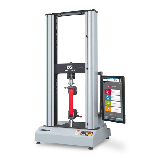
Chapter: Introduction System Description and Terminology ® Figure 1. 3400 Dual Column Table Model with Bluehill Operator Dashboard - Front View M10-17322-EN... - Page 15 System Description and Terminology Legend for Figure 1 Label Component T-slots Top plate Column cover Load cell Upper limit switch Limit switch actuator Lower limit switch Emergency stop button Frame control panel ® Bluehill Operator Dashboard (optional) Product Support: www.instron.com...
- Page 16 Chapter: Introduction Figure 2. 3400 Dual Column Table Model - Rear View M10-17322-EN...
-
Page 17: Components
® contacting extensometer. Contact your regional Instron office or check our web site at www.instron.com for assistance with Instron’s grips and fixtures. The following table defines the components of the testing system: Product Support: www.instron.com... -
Page 18: Principle Of Operation
The load cell converts this load into an electrical signal that the software measures and displays. ® ® Bluehill Instron Software testing software that controls the testing system, running tests and analyzing test data to produce test results. Specimen A single piece of material to be tested. -
Page 19: Software
Frame control panel - holds all the controls and indicators for the testing system. Software ® Control of the testing system is carried out via Instron Bluehill software. Setting test parameters, operating the system, and collecting test data is done through the software program. - Page 20 Chapter: Introduction Table 3. Safety and Information Labeling Descriptions (Continued) Label Meaning Purpose Disconnect power Disconnect the power supply before supply servicing machine. Electrical - fuse warning Indicates an electrical hazard exists. Advises disconnecting power mains before changing fuses and using only specified fuses.
-
Page 21: Product Support
® If you cannot find answers in these sources, contact Instron Service directly. A list of ® Instron offices is available on our website at www.instron.com. In the US and Canada, you can call directly at 1-800-473-7838. Product Support: www.instron.com... -
Page 22: Product Documentation
® Instron offers a comprehensive range of documentation to help you get the most out of your Instron products. Depending on what you have purchased, your documentation may include some or all of the following: Operator’s Guide How to use your system components and controls, procedures for setting limits, calibration and other frequently performed operating tasks. -
Page 23: Chapter 2: Requirements
Environmental specifications ......... 28 • 34TM-50 Power Requirements and Cords....... 30 •... -
Page 24: Supplier's Responsibilities
Under Instron’s standard contract, the shipping terms are Ex-Works (or FOB Factory), meaning ownership and liability for the testing system transfers to the customer at Instron’s loading dock. Unless other shipping terms are specified in a purchase order, which Instron does not dispute, the Ex-Works shipping terms apply. Under these terms, the customer is responsible for securing the applicable transit insurance on the shipment and arranging safe transport to the final destination. -
Page 25: Site Requirements
Site requirements Instron is responsible for insurance cover while the testing system is in the factory up until it reaches the loading dock for shipping. Installation When the site location is prepared and the frame and its components have been moved ®... -
Page 26: Frame Location
® Instron systems require “clean” and stable electrical power. Unless other ® arrangements are made with Instron , you are responsible for providing clean electrical power. An in-line power surge protector is recommended for all installations. M10-17322-EN... -
Page 27: Telephone And Network Access
Our goal is to provide remote diagnostics in order to resolve system issues. ® Having a network drop or digital phone line available will enable an Instron service representative to connect to the testing system to diagnose and resolve problems more efficiently. -
Page 28: Environmental Specifications
Chapter: Requirements Dry compressed air Dry, compressed air is required for pneumatic grips. Typically, 90 psi air is required with a water trap/filter. Water supply A water supply may be required for some specimen grips and some temperature control systems. Liquid nitrogen and carbon dioxide A liquid nitrogen (LN2) or carbon dioxide (CO2) supply may be required for environmental chambers with cooling options. -
Page 29: Conformity With Eu Directives
Care must be taken at the end of the equipment's life to ensure its disposal in accordance with local environmental regulations. Because of the wide range of applications where our instruments are used, Instron has no knowledge of the environmental impact of the customer's test pieces or specimens. -
Page 30: 34Tm-50 Power Requirements And Cords
The noise output from equipment used for materials or structures testing is also depen- dent upon the items under test. Instron recommends that users carry out their own noise level measurements to ensure the continuous safety and comfort of personnel. -
Page 31: Power Cord Selections
34TM-50 Power Requirements and Cords Power cord selections ® If you do not make a choice, Instron chooses the customary power cord that matches the shipping destination for the system. Table 6. Power cords Power cord designation Matching receptacle Locale... -
Page 32: Checklist For Site Preparation
Instron Service or your local Instron office for assistance. Not all computers are compatible with Instron testing systems. If you intend to purchase ® a computer from an outside vendor, contact Instron Service to verify its compatibility. -
Page 33: Transporting
Pathway from the loading dock to the final site location has sufficient width and height to fit the frame and forklift (or crane). Measure all doors and hallways. Refer to “34TM-50 Dimensions and Weight” on page for dimensions and weights of the testing system without its packaging. Refer to “34TM-50 Packaging... -
Page 34: Scheduling Installation
When the testing site is ready, and the frame has been moved to its final operating ® location, contact Instron to schedule an installation appointment. ® A list of Instron offices is available on our website at www.instron.com. In the United States and Canada, you can call 1-800-473-7838. M10-17322-EN... -
Page 35: Chapter 3: Specifications
34TM-50 Dimensions and Weight ........ - Page 36 Chapter: Specifications Table 8. 34TM-50 dimensions - extra height Letter Designation Description Dimension - mm (inch) Overall height 2131 (83.9) Maximum vertical test space (test daylight - from 1700 (66.9) base to underside of crosshead) Minimum vertical test space (test daylight - from 93 (3.7)
- Page 37 34TM-50 Dimensions and Weight B1 MIN. B2 MAX. Figure 3. 34TM-50 frame dimensions - front view Product Support: www.instron.com...
- Page 38 Chapter: Specifications D MAX Figure 4. 34TM-50 frame dimensions - side view M10-17322-EN...
-
Page 39: System Weight
All measurements in the following figures are shown in mm. Table 11. Meaning of symbols on dimension drawings Symbol on drawing Meaning diameter depth THRU through-hole left hand thread right hand thread arrow pointing to the front of the load frame Product Support: www.instron.com... -
Page 40: Base Beam Dimensions
Chapter: Specifications Base beam dimensions 36.50 40.038 3.25 3.00 40.000 100 PCD 7X M10 120° TYP. 5.70 5.40 Figure 5. View of base beam from above Crosshead dimensions 8X M10 55 PCD 3.13 40.038 45° 17 THRU 3.00 40.000 60° 20.50 3.44 Figure 6. -
Page 41: Top Plate Dimensions
Accessory Mounting Dimensions 14 THRU Figure 7. View of top of crosshead Top plate dimensions 4X M10 THRU Figure 8. View of underside of top plate Product Support: www.instron.com... -
Page 42: System Performance
Chapter: Specifications System Performance Table 12. 34TM-50 system performance Parameter Specifications Testing type Tension, compression, and through zero operation. Basic control mode Closed loop position control Load capacity - kN (lbf) 50 (11240) Maximum speed - mm/min (in/min) 508 (20) Minimum speed - mm/min (in/min) 0.05 (0.002) -
Page 43: Chapter 4: Risk Reduction And Safe Use
• the experience of the operator using the equipment It is our strong recommendation, therefore, that you carry out your own risk assessment for your particular equipment setup and testing application. Product Support: www.instron.com... -
Page 44: Rapid Crosshead Motion
Chapter: Risk reduction and safe use Each of the following sections describes a specific hazard zone of the testing system and lists the most common risks for testing using this equipment. Use the information in the following sections, together with the instructions in the remainder of this manual, to conduct your own risk assessment. - Page 45 Use a specimen insertion tool to keep fingers out of the space between the fixtures. • Use an interlocked shield to limit or disallow motion when the shield door is open. When the space is less than 25mm, the crush hazard is very significant, so this is the best option. Product Support: www.instron.com...
-
Page 46: Pinching Fingers Between Grip Jaw Faces
Chapter: Risk reduction and safe use Pinching fingers between grip jaw faces Warning Pinch hazard to fingers. This hazard relates to grip jaws closing quickly, pinching fingers. Recommendations For 2712 Series pneumatic grips: • In the documentation supplied with the grips, read and follow the safety recommendations for installing a specimen. -
Page 47: Impact Of Debris From Breaking Specimens
Hazard from flying debris. This hazard relates to brittle or composite specimens that can explode when they break. Recommendations For less dangerous debris (specimen dust or fibers, for example): • Use personal protection equipment (for example safety glasses). Product Support: www.instron.com... -
Page 48: Operator Protection Overview
Chapter: Risk reduction and safe use For more dangerous projectile debris (brittle composite specimens, for example): • Use an interlocked shield. Operator Protection Overview The majority of hazards for operating materials testing systems are associated with: • rapid movement of the crosshead causing crush injuries •... - Page 49 Operator Protection lets an Administrator configure the testing system to be consistent with the risk assessment for that system. Access to the controls for Operator Protection is password protected. If you have ® Administrator rights you can modify Operator Protection in the Admin tab in Bluehill Product Support: www.instron.com...
- Page 50 Chapter: Risk reduction and safe use M10-17322-EN...
-
Page 51: Chapter 5: Lifting And Handling
General handling precautions ........51 • 34TM-50 Packaging dimensions and weight ......51 •... -
Page 52: Unpack Dual Column Frames
4. Use the packing list to inventory all the boxed items. Some accessories may be in the container with the load frame or may be packaged separately. Do not open any of the packing boxes until the Instron service engineer arrives to install your testing system. The packing list indicates the total number of boxes that are included in the shipment. -
Page 53: Transport Dual Column Frames
• Crane method - using a crane with slings to lift the load frame from the crosshead. ® Instron strongly recommends using professional riggers experienced in moving heavy equipment. Warnings Hazard - do not lift the frame by the base. -
Page 54: Before You Begin
If the frame is still in its packaging, check the packaging dimensions for your frame model (“34TM-50 Packaging dimensions and weight” on page 51). If you are moving the frame without its packaging, check the dimensions for your frame model (“34TM-50 Dimensions and Weight”... -
Page 55: Crosshead Method
This method can be used to: • Transport the load frame to the site location. • Lift a tabletop load frame onto a table or workbench. • Lift the frame to remove the transport skid from the frame’s base. Product Support: www.instron.com... - Page 56 Chapter: Lifting and handling Figure 9. Lifting the Frame from the Crosshead 1. Ensure that there are no shipping bolts attached to the skid. 2. Using a forklift with padded forks or protective material around the crosshead, care- fully insert the forks under the crosshead between the columns. See Figure 9 page 56.
-
Page 57: Shipping Skid Method
1. Ensure that the frame is bolted to the shipping skid. 2. Carefully insert the forks under the shipping skid as shown in Figure 10 on page 57. 3. The crosshead should be in its lowest position so that the frame is not top heavy. Product Support: www.instron.com... - Page 58 Chapter: Lifting and handling Warning Crush hazard - Ensure that all persons in the immediate area are standing away from the frame during lifting. Do not lift the frame more than 8 cm (3 in) off the floor. 4. Slowly and carefully lift the frame off the floor. 5.
- Page 59 Transport dual column frames Crane method Caution ® Instron STRONGLY recommends using professional riggers experienced in moving heavy equipment. Figure 11. Lifting Load Frame with a Crane 1. Attach the lifting sling to the crosshead and secure it to the crane hook such that the...
- Page 60 Chapter: Lifting and handling Caution Ensuring that the sling extends vertically from the front of the crosshead minimizes the risk of damage to the top plate. When the frame is lifted, it will tilt toward the rear. Warning Crush hazard - Ensure that all persons in the immediate area are standing away from the frame during lifting.
- Page 61 ....29 Instron......24 initial operation of the system .
- Page 62 system performance ....42 table loading ......26 technical support .
- Page 64 www.instron.com...
Need help?
Do you have a question about the 34TM-50 and is the answer not in the manual?
Questions and answers