Instron 6800 Series Operator's Manual
Column table model
Hide thumbs
Also See for 6800 Series:
- Preinstallation manual (56 pages) ,
- Operator's manual (108 pages)
Table of Contents
Advertisement
Advertisement
Table of Contents
Troubleshooting

Related Manuals for Instron 6800 Series


Summary of Contents for Instron 6800 Series
- Page 1 6800 Series Single Column Table Model Operator’s Guide M10-17410-EN Revision A...
- Page 2 Instron is a registered trademark of Illinois Tool Works Inc. (ITW). Other names, logos, icons and marks identifying Instron products and services referenced herein are trademarks of ITW and may not be used without the prior written permission of ITW.
- Page 3 Caution is used where a hazard may lead to damage to equipment or to loss of data. Instron products, to the best of its knowledge, comply with various national and international safety standards, in as much as they apply to materials and structural testing.
- Page 4 Preliminary Pages Warnings Hazard - Press the Emergency Stop button whenever you consider that an unsafe condition exists. The Emergency Stop button removes hydraulic power or electrical drive from the testing system and brings the hazardous elements of the system to a stop as quickly as possible.
- Page 5 During system operation, keep away from the operating envelope of the robot. De-activate the robot before entering the envelope for any purpose, such as reloading the specimen magazine. Product Support: www.instron.com...
- Page 6 Preliminary Pages Warnings Hazard - Set the appropriate limits before performing loop tuning or running waveforms or tests. Operational limits are included within your testing system to suspend motion or shut off the system when upper and/or lower bounds of actuator or crosshead travel, or force or strain, are reached during testing.
- Page 7 Apply the specified torque to all load string fasteners and the correct setting to wedge washers or spiral washers. Visually inspect highly stressed components such as grips and threaded adapters prior to every fatigue test for signs of wear or fatigue damage. Product Support: www.instron.com...
- Page 8 Preliminary Pages M10-17410-EN...
-
Page 9: Table Of Contents
First time startup ............Product Support: www.instron.com... - Page 10 Preliminary Pages Chapter 4: Function of controls ......... 49 Power input connector .
- Page 11 Lubrication ............Product Support: www.instron.com...
- Page 12 Preliminary Pages Lubricate ballnuts and linear guide carriages ......General Maintenance Procedures..........Test Limit Stops.
- Page 13 (carried out by an ® Instron service engineer for first-time installation) • ® configuring the system before you start testing (carried out by an Instron service engineer for first-time installation) • routine maintenance of the system •...
-
Page 14: Chapter 1: Introduction
• perform routine maintenance of the system ® These instructions do not include the development of Bluehill test methods. This is ® covered in more advanced training that can be provided by the Instron Service and Training departments. M10-17410-EN... -
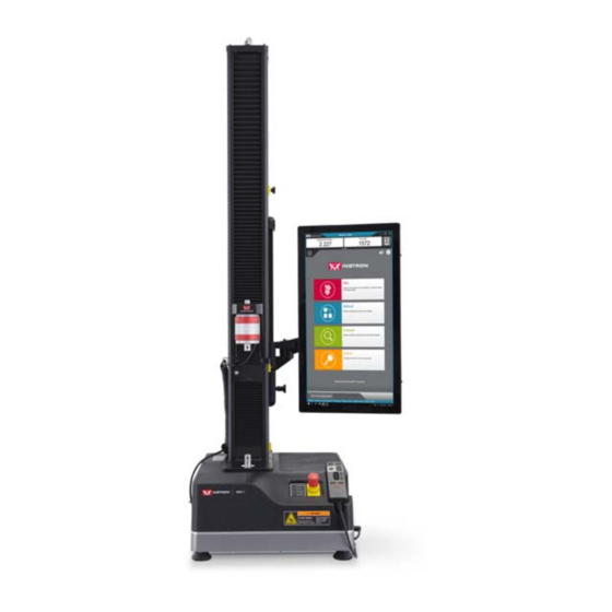
Page 15: System Description And Terminology
System Description and Terminology System Description and Terminology ® Figure 1. 6800 Single Column Table Model with Bluehill Operator Dashboard - Front View Product Support: www.instron.com... - Page 16 Chapter: Introduction Legend for Figure 1 Label Component Ballscrew cover Top plate Column cover Load cell Upper limit switch Limit switch actuator Lower limit switch Emergency stop button Indicator panel ® Bluehill Operator Dashboard (optional) Handset M10-17410-EN...
- Page 17 System Description and Terminology Figure 2. 6800 Single Column Table Model - Rear View Product Support: www.instron.com...
-
Page 18: Components
® contacting extensometer. Contact your regional Instron office or check our web site at www.instron.com for assistance with Instron’s grips and fixtures. The following table defines the components of the testing system: M10-17410-EN... -
Page 19: Principle Of Operation
The load cell converts this load into an electrical signal that the software measures and displays. ® ® Bluehill Instron Software testing software that controls the testing system, running tests and analyzing test data to produce test results. Specimen A single piece of material to be tested. -
Page 20: Software
Handset - holds all the controls for the testing system. Software ® Control of the testing system is carried out via Instron Bluehill software. Setting test parameters, operating the system, and collecting test data is done through the software program. - Page 21 Indicates that a rotating hazard exists. hazard Keep clear of these areas (and tie back long hair and loose clothing). Ground stud Indicates a ground stud. Read the manual Read and understand the operator’s manual before using the machine. Product Support: www.instron.com...
-
Page 22: Conformity With Eu Directives
For advice on the disposal of electrical and electronic equipment in your country, contact your local Instron representative. Conformity with EU directives ® Instron declares under our sole responsibility that 68SC and 68TM testing systems are in conformity with all relevant provisions of the following regulations: •... -
Page 23: Product Support
If you cannot find answers in these sources, contact Instron Service directly. A list of ® Instron offices is available on our website at www.instron.com. In the US and Canada, you can call directly at 1-800-473-7838. Product Documentation ® Instron offers a comprehensive range of documentation to help you get the most out of your Instron products. -
Page 24: Location Of Your Preinstallation Manual
Chapter: Introduction We welcome your feedback on any aspect of the product documentation. Please email info_dev@instron.com with your comments. Location of your Preinstallation manual A copy of the Preinstallation manual for your model was sent upon receipt of your order to assist you to prepare for the arrival of your shipment. -
Page 25: Chapter 2: Risk Reduction And Safe Use
Each of the following sections describes a specific hazard zone of the testing system and lists the most common risks for testing using this equipment. Use the information in the following sections, together with the instructions in the remainder of this manual, to conduct your own risk assessment. Product Support: www.instron.com... -
Page 26: Rapid Crosshead Motion
Chapter: Risk reduction and safe use Rapid crosshead motion Warning Crush hazard to fingers or hands. This hazard relates to grips and fixtures coming together as a result of rapid crosshead motion, crushing hands or fingers. For example, an operator inadvertently commands the system to jog or return while their hands are in test area. - Page 27 Use a specimen insertion tool to keep fingers out of the space between the fixtures. • Use an interlocked shield to limit or disallow motion when the shield door is open. When the space is less than 25mm, the crush hazard is very significant, so this is the best option. Product Support: www.instron.com...
-
Page 28: Pinching Fingers Between Grip Jaw Faces
Chapter: Risk reduction and safe use Pinching fingers between grip jaw faces Warning Pinch hazard to fingers. This hazard relates to grip jaws closing quickly, pinching fingers. Recommendations For 2712 Series pneumatic grips: • In the documentation supplied with the grips, read and follow the safety recommendations for installing a specimen. -
Page 29: Impact Of Debris From Breaking Specimens
This hazard relates to brittle or composite specimens that can explode when they break. Recommendations For less dangerous debris (specimen dust or fibers, for example): • Use personal protection equipment (for example safety glasses). For more dangerous projectile debris (brittle composite specimens, for example): • Use an interlocked shield. Product Support: www.instron.com... -
Page 30: Operator Protection Overview
Chapter: Risk reduction and safe use Operator Protection Overview The majority of hazards for operating materials testing systems are associated with: • rapid movement of the crosshead causing crush injuries • rapid closing of pneumatic grips causing pinch injuries ® Operator Protection in Bluehill provides a mechanism that lets you limit crosshead jog speed and reduce grip closing pressure while you are setting up a test. -
Page 31: Installation
Refer to Figure 3 on page and follow the procedure. Figure 3. Adjust the leveling feet You need the following equipment (supplied in the ancillary parts kit unless specified otherwise): Product Support: www.instron.com... -
Page 32: Power Supply Compatibility
Chapter: Installation • Spirit level (not supplied) • 19mm combination wrench (part no. P632-484) • 16mm thin open-ended wrench (part no. P632-482) Caution Make sure that the full weight of the frame is bearing down on the feet. If it is not, you will not be able to adjust the feet. - Page 33 Observe the CEE wire color code as follows: • Brown - high (live) • Light blue - low (neutral) Product Support: www.instron.com...
-
Page 34: Set The Input Voltage
Chapter: Installation • Green and yellow - earth (ground) Set the input voltage The load frame voltage is factory set according to the voltage that was specified at the time of purchase. Use the following procedures only if the facility power source does not match the frame voltage setting. - Page 35 2. Insert a small flat-head screwdriver into the middle of the connector and pry out the fuse holder (1), as shown below. 3. Remove the fuse holder (1) from the power input connector, exposing the voltage selector card (2) as shown below. Product Support: www.instron.com...
- Page 36 Chapter: Installation 4. Using long-nose pliers, remove the voltage selector card (2) as shown below. The voltage indicator pin is labeled (3). 5. Position the voltage selector card so the indicator pin (3) points upward, as shown below. Holding the pin in this position, rotate the card until the required voltage setting shows at the bottom of the card.
-
Page 37: System Components
10. Before you carry out any testing, perform the procedure described in “First time startup” on page 47. System components ® Instron Service installs your testing system. These diagrams and instructions are provided as a reference if you need to move the system after the initial installation. Product Support: www.instron.com... -
Page 38: Single Column Load Frame
Chapter: Installation Single column load frame Figure 5. Frame connections Legend for Figure 5 Label Component More detail Mains cable and plug Ground connectiton (when required) “Ground connection detail” on page ® To Bluehill Operator Dashboard or separate computer (not shown in Figure System ID label M10-17410-EN... - Page 39 “Controller connections detail” on page Adjustable feet “Level the load frame” page Power inlet connection, power switch, “Power supply fuses and voltage selector compatibility” on page Not shown Connector for handset On right hand side of frame Product Support: www.instron.com...
- Page 40 Chapter: Installation Rear panel connections detail Figure 6. Rear panel connections detail Legend for Figure 6 Label Component More detail 1 (optional) Pneumatic grips - grip 1 connector (typically upper grip) 2 (optional) Pneumatic grips - grip 2 connector (typically lower grip) 3 (optional) Pneumatic grips - air inlet connector 120 psi (8.3 bar) maximum...
- Page 41 Figure 7 Label Component More detail Encoder connector Connects to various accessories, including AVE2 and AutoX extensometers Foot switch connector Status indicators PIP jack Strain connectors Optional Status indicators Force connector Connects to load cell Sync connector Product Support: www.instron.com...
- Page 42 Chapter: Installation Label Component More detail ® Service connectors For use by Instron Service only Expansion connector Optional I/O (Input/Output) connector Optional Ground connection detail If the electrical supply is not grounded, you must use this functional ground connection to connect the frame to a suitable ground in the building.
-
Page 43: Connect The System Components
6. Use the cable clips on the column to secure the load cell cable and pneumatic grip connections (see “Single column load frame” on page 38). ® 7. Instron systems provide an option to measure strain. If your system is equipped to measure strain, connect the extensometer to the connection on the STRAIN 1 controller (see “Controller connections detail”... -
Page 44: Bluehill ® Operator Dashboard
Chapter: Installation Caution ® The connectors labeled SERVICE are for the use of Instron Service only. Never connect any equipment to any of the SERVICE connectors. 8. If the frame or any accessories require a ground (earth) connection, make the connections (refer to “Ground connection detail”... - Page 45 If you need to move the testing system you must disconnect and remove the Bluehill Operator Dashboard as follows: 1. Ensure that the power switch is set to Off and the mains power cable is disconnected. ® 2. Disconnect all cables that connect to or from the Bluehill Operator Dashboard. Product Support: www.instron.com...
- Page 46 Chapter: Installation Figure 10. Mounting arm 3. If necessary, loosen the set screw on the side of the “elbow” on the mounting arm (1 Figure 10 on page 46). 4. Operate the release mechanism on top of the “elbow” (2 in Figure 10 on page 46) ®...
-
Page 47: First Time Startup
Operator Dashboard face down on a soft material to avoid scratching the screen. First time startup ® When the testing system is installed, you need to configure Bluehill to communicate with the testing hardware. 1. Ensure that all cables are properly installed and securely connected. Product Support: www.instron.com... - Page 48 Chapter: Installation 2. Turn the power switch on the machine to the On ( ) position. The white LED above the DISABLED indicator flashes. ® 3. Turn on the power to the Bluehill Operator Dashboard and any other accessories that make up the testing system. ®...
-
Page 49: Chapter 4: Function Of Controls
Pneumatic Grips ........... 68 Before you start the system, make sure you familiarize yourself with the following controls: Product Support: www.instron.com... -
Page 50: Power Input Connector
Chapter: Function of controls Power input connector Figure 12. Power input connector Legend for Figure 12 Label Component Power switch IEC inlet connector Fuse carrier and voltage selector access Selected voltage The power input connector, shown in Figure 12 on page 50, performs the following functions: •... -
Page 51: Emergency Stop Button
All the controls for the testing system are on the handset. When you operate a control on the handset, any change to the testing mode is displayed on the indicator panel (refer to “Indicator Panel” on page 54). Product Support: www.instron.com... - Page 52 Chapter: Function of controls Figure 14. Handset Legend for Figure 14 Label Description Softkeys 1 and 2 These softkeys duplicate the functions assigned to Softkey 1 and 2 in ® Bluehill software. Buttons illuminate white when available. M10-17410-EN...
- Page 53 Press this button to toggle on or off the SPECIMEN PROTECT function. This function protects the test specimen and load string components from overloads. Button illuminates white when available and changes to green when you activate it. Product Support: www.instron.com...
-
Page 54: Indicator Panel
Chapter: Function of controls Label Description ZERO DISPLACEMENT button Press this button to set the current position of the crosshead as the zero displacement point (or gauge length) position. After setting the zero displacement point, the crosshead returns to this position when: •... -
Page 55: Bluehill ® Software
SET UP (blue) • (yellow) CAUTION • TESTING (red) ® Bluehill software The software controls: • setting test parameters • collecting and analyzing test data ® Refer to the Bluehill online help and reference for more details. Product Support: www.instron.com... -
Page 56: Home Screen
This button is hidden if Security is not enabled. ® Instron Connect Uses an Internet connection to check the status of the system, including verification status of transducers. Checks for software updates. - Page 57 Method - the name of the current method file that is open, if any. • Report - the name of the current report template that is open, if any. • Progress messages - various messages indicating progress, for example “Opening”, “Closing” and “Generating”. Product Support: www.instron.com...
-
Page 58: Operator Protection
Chapter: Function of controls Operator Protection ® Operator Protection in Bluehill provides a mechanism that lets you limit crosshead jog speed and reduce grip closing pressure while you are setting up a test. Operator Protection lets an Administrator configure the testing system to be consistent with the risk assessment for that system. - Page 59 (no greater than 600 mm/min) • pneumatic grips can close at the initial grip pressure (default value of 15 psi) The frame returns to set up mode when: Product Support: www.instron.com...
- Page 60 Chapter: Function of controls • the test is paused (e.g. during extensometer removal) • after a test is complete • after a return is complete • when an interlocked shield is opened To proceed to CAUTION mode, you press the UNLOCK button.
-
Page 61: Move Between Modes
Crosshead speed ramps up gradually to the maximum speed of the frame. Move between modes The following table shows how the controls on the handset move the system between modes to set up and run a test. Product Support: www.instron.com... - Page 62 Chapter: Function of controls Table 5. Move between modes Initial condition Action Result DISABLED SET UP Press (white) (blue) System remains in set up mode until you make a change. During this time you can: • move the crosshead at the restricted speed set up in the Admin tab, up to a maximum of 600 mm/min •...
- Page 63 If you are using toggle switches on the grips to control them, the grips are at full pressure only during TESTING mode. Typical test flow “Move between modes” on page describes each of the test controls and how they are used to move between testing modes. Product Support: www.instron.com...
-
Page 64: Jog At High Speed
Chapter: Function of controls For a step-by-step description of a typical test flow using these controls, refer to “Testing a sample” on page 91. This section contains two procedures, one for systems using an interlock and one for systems without an interlock. Jog at High Speed Under normal conditions, in SET UP... -
Page 65: Operator Protection Controls
The interlock automatically transitions the system to CAUTION mode when the interlock is closed. If there is no interlock, you must press the UNLOCK button to transition to CAUTION mode. Product Support: www.instron.com... -
Page 66: Bluehill ® Operator Dashboard
Chapter: Function of controls Control Description Pneumatic grips Enables and disables pneumatic grips connected to the testing system with the integrated air kit. Grip control Footswitch (when pneumatic Default is . You close both grips using the grips are enabled) integrated air kit and foot switch. -
Page 67: Basic Touch Functions
(landscape orientation) to display a panel that lets you quickly include or exclude a specimen from the sample • any scrollable screen component - flick up or down, left or right to quickly scroll through the list Product Support: www.instron.com... -
Page 68: Pneumatic Grips
Other pneumatic grips can be used with the system, including operation with the integrated air kit and footswitch, but they may not be designed to utilize the full range of ® features of Operator Protection. Contact Instron Service for advice. How Operator Protection works with grips... - Page 69 (screw fully counterclockwise). Do not use the air inlet flow adjustment control to reduce air flow as you risk transitioning from initial pressure to full pressure before the grips have closed. If the Product Support: www.instron.com...
-
Page 70: Operate Grips Using Footswitch
Chapter: Function of controls grips do not close completely at the initial pressure, they will close at full force when the grips transition to full pressure. In addition to the hazard caused by reducing the air flow, operation of the air inlet flow adjustment control can result in an inaccurate grip pressure reading which may disable the frame. - Page 71 3. Press the UNLOCK button to transition to CAUTION mode. The grips pressurize to full pressure. Product Support: www.instron.com...
-
Page 72: Operate Grips Using Toggle Switches
Chapter: Function of controls 4. Within 2 seconds, press the START TEST button to start the test. If you do not start the test immediately and the system returns to SET UP mode, the grips continue at full pressure until you run a test or release the grips. The system transitions to TESTING mode. - Page 73 The system transitions to mode and the grips pressurize to full pressure. TESTING 6. Stop the test, or the test ends. The system reverts to SET UP mode and the grip pressure returns to the initial grip pressure. Product Support: www.instron.com...
-
Page 74: Grips Not In Use
Chapter: Function of controls Caution If your test ends and the specimen has stored energy, e.g. the specimen did not break, the specimen may slip out of the grips when the grip pressure reduces at the end of the test. If this could be an issue, it is recommended that you set the point of control for grips to Footswitch and use a footswitch for your tests. -
Page 75: Chapter 5: Assemble The Load String
It includes the load cell, grips, the specimen and any adapters that let you connect any of these components together. ® Instron Service sets up the testing machine during installation, but you may need to change one or more of these components for different types of testing. - Page 76 If you have a load cell that is not listed, contact Instron for advice on compatibility and adapters that may be available for your load cell. Table 8.
-
Page 77: Before You Begin
The crosshead is positioned below its travel midpoint so that you can easily and safely access the crosshead. • The frame is in the disabled state, i.e. the white LED above the indicator DISABLED on the indicator panel is illuminated. Product Support: www.instron.com... -
Page 78: Install The Load Cell
Chapter: Assemble the load string Install the load cell Install a 2530 load cell (capacities 5 N through 100 N) 5N - Figure 15. Install a 2530 series load cell - capacities 5 N through 100 N Legend for Figure 15 Label Component Part number... - Page 79 12. Calibrate the load cell (refer to “Calibrate a transducer” on page 99). 13. Leave the system on for at least 15 minutes to allow the load cell circuitry to stabilize. After this warm-up period, calibrate the load cell again. Product Support: www.instron.com...
-
Page 80: Install A 2580 Load Cell (Capacities 500 N Through 5 Kn)
Chapter: Assemble the load string Install a 2580 load cell (capacities 500 N through 5 kN) Figure 16. Install a 2580 series load cell - capacities 500 N through 5 kN Legend for Figure 16 Label Component Part number Screw, M10 x 40 201V57 M10 load washer 610J9... - Page 81 12. Calibrate the load cell (refer to “Calibrate a transducer” on page 99). 13. Leave the system on for at least 15 minutes to allow the load cell circuitry to stabilize. After this warm-up period, calibrate the load cell again. Product Support: www.instron.com...
-
Page 82: Adapters
Chapter: Assemble the load string Adapters Adapters let you connect grips or fixtures to the frame when the interfaces have different connection sizes. There are two types of adapters: base adapters and coupling adapters. Base adapters Base adapters let you connect grips and fixtures to the base of the load frame. The load frame is are supplied with a Type O base adapter installed. - Page 83 Type O base adapter Legend for Figure 17 Label Component Part number Grip Compression spring 66-1-1080 M6 screw 201V35 Clevis pin T1223-1034 Clevis pin clip T1223-1031 Type O base adapter Load cell anti-rotation pin (x2) 705K84 Load frame base beam Product Support: www.instron.com...
- Page 84 Chapter: Assemble the load string Figure 18. Type D base adapter Legend for Figure 18 Label Component Part number Grip Compression spring 66-5-6 M6 screw 201V35 Clevis pin T29-515 Clevis pin clip T1223-1053 Type D base adapter T581-48 Load cell anti-rotation pin (x2) 705K84 Load frame base beam 1.
-
Page 85: Coupling Adapters
For example, if you need to connect a load cell with a Type D (female) connector to a grip with a Type O (male) connector you require a Type Dm to Of adapter. Product Support: www.instron.com... -
Page 86: Select Grips And Fixtures
Chapter: Assemble the load string Select Grips and Fixtures A set of grips are installed on the system during installation by a service engineer. If your testing requires it, you may need to install a different set to obtain optimum test results. The selection of grips depends on the material, geometry and strength of the test specimen. - Page 87 4. Repeat steps 1 through 3 to install the lower grip onto the load frame base adapter. 5. When both grips are installed, follow the procedure to preload the load string (refer “Preload the load string” on page 88). Product Support: www.instron.com...
-
Page 88: Preload The Load String
Chapter: Assemble the load string Figure 19. Typical grip installation Preload the load string This procedure eliminates backlash and deflections within the load string which can degrade the integrity of test results, especially when testing at high loads. The procedure involves preloading the entire load string and then hand-tightening all the lock nuts on all the grips and couplings. - Page 89 When you next need to change grips or any other part of the load string, the locknuts will be too tight to loosen by hand. You will need to follow the procedure “Unload the load string” on page Product Support: www.instron.com...
-
Page 90: Unload The Load String
Chapter: Assemble the load string Unload the load string If you have followed the procedure to preload the load string (“Preload the load string” on page 88) you will need to follow this procedure before you can change grips or any or any other part of the load string. The locknuts will be too tight to loosen by hand. -
Page 91: Chapter 6: Testing Specimens
An interlock is an optional accessory that changes the behavior of the system depending on whether the interlock circuit is open or closed. For example, the door on a protective shield may include an interlock. When the interlock circuit is open (e.g. the Product Support: www.instron.com... -
Page 92: Testing With No Interlock
Chapter: Testing specimens shield door is open), the circuit is interrupted and the system is either disabled or restricted as defined by the Operator Protection settings. Testing with no interlock This test scenario assumes the system has no accessories with an interlock and that the start test method in Operator Protection settings is set to Frame control (the default). - Page 93 11. Use the jog controls to move the crosshead to its starting position and set zero displacement. Refer to “Set the zero displacement point” on page 103. 12. Balance the Force transducer configuration. Refer to “Balance a transducer configuration” on page Product Support: www.instron.com...
- Page 94 Chapter: Testing specimens 13. Install the specimen into the grips. Refer to the documentation provided with the grips for details. If the system includes pneumatic grips, refer to “Pneumatic Grips” on page 68. 14. Verify that the specimen is aligned properly in the grips. 15.
-
Page 95: Testing With An Interlock
The high energies involved in testing can cause broken parts of a specimen to be projected forcefully some distance from the test area. Wear eye protection and use protective shields or screens whenever a risk of injury to operators and observers exists from the failure of a test specimen. Product Support: www.instron.com... - Page 96 Chapter: Testing specimens Select the correct test area for the test. An incorrectly set test area can cause unanticipated crosshead behavior. Press the Emergency Stop button if the frame moves in an unexpected direction. An incorrectly set test area can cause unanticipated crosshead behavior and create a safety hazard that may damage the specimen or load cell.
- Page 97 21. After the test is complete, the system transitions to CAUTION mode. If the specimen did not break, use the jog controls to relieve the applied force from the specimen before opening the interlock to remove the specimen. Product Support: www.instron.com...
-
Page 98: Create A New Sample
Chapter: Testing specimens 22. Open the interlock to remove the specimen pieces from each grip. The system behavior depends upon how the interlock behavior is configured under Operator Protection: • Disable frame option: the system transitions to DISABLED mode when the interlock is open. -
Page 99: Calibrate A Transducer
LVDT transducer, the Calibration point field becomes available for ® automatic calibration. The calibration point field is intended primarily for Instron ® Service and should only be used by the service personnel. Contact Instron Service for assistance. 1. Select in the console area to open System Details. -
Page 100: Manual Calibration
Chapter: Testing specimens 8. The calibration was successful if a value displays in the transducer live display area and the transducer icon in System Details is no longer grayed. 9. Close the Transducer Settings dialog. 10. Close System Details. The calibration is saved with the transducer configuration and is restored whenever the transducer configuration is selected. - Page 101 System Details. 2. In the System Settings area, select the icon for the transducer to open the Transducer Settings dialog. 3. Under Settings, select the transducer configuration in the Transducer configuration field. 4. Set Calibration type to Manual. Product Support: www.instron.com...
- Page 102 Chapter: Testing specimens 5. Enter the full scale value of the transducer. 6. For strain transducers, enter the gauge length of the extensometer. The system must know the gauge length of the installed extensometer in order to calculate strain values for display and for further calculations. 7.
-
Page 103: Set The Zero Displacement Point
Activating a second-level limit switch disables the drive system so you cannot move the crosshead. The second level limits are internal to the machine. They are calculated relative to the first level limits and cannot be independently set. Product Support: www.instron.com... -
Page 104: Set The Crosshead Limit Stops
Chapter: Testing specimens Set the crosshead limit stops 1. Ensure that the crosshead is stationary and that the test parameters are set. When setting limit stops, allow for an additional 3 mm of crosshead travel after the actuator activates a limit stop. There is a small delay time from the point when the actuator hits the limit stop and when the message relays to the limit switches located in the frame base. -
Page 105: Move Off A Crosshead Limit Stop
7. Close the Transducer Settings dialog. 8. Close System Details. These settings are saved with the transducer configuration and are restored whenever the transducer configuration is selected. Balance a transducer configuration Calibrate the transducer before you balance it. Product Support: www.instron.com... -
Page 106: Stop A Test
Chapter: Testing specimens 1. Make sure that no specimen is installed. 2. Select in the console area to open System Details. 3. In the System Settings area, select the icon for the transducer to open the Transducer Settings dialog. 4. Under Settings, select the transducer configuration in the Transducer configuration field. - Page 107 Open the interlock. b. Close the interlock. • In addition, in a system with interlocks where the interlock behavior is configured under Operator Protection to Allow limited motion: a. Press the UNLOCK button on the handset. Product Support: www.instron.com...
-
Page 108: Crosshead Limit Switches
Chapter: Testing specimens Crosshead Limit Switches The test stops if the crosshead contacts the upper or lower limit stops. If this happens, use the jog controls to move the crosshead away from the limit. Software Event When the system encounters a pre-set limit or event set from the software, the test stops. -
Page 109: Troubleshooting
Identify and resolve the condition that caused the secondary overtravel limit to trip before you use the ® testing system again. Contact Instron Service for assistance. You press the Emergency Stop button Refer to “Emergency Stop Button”... - Page 110 Chapter: Testing specimens M10-17410-EN...
-
Page 111: Chapter 7: Maintenance
To ensure that the frame continues working at its optimal performance, it is ® recommended that the machine receive an annual service check. Instron Service can perform this annual service, and replace any damaged or worn parts to ensure that your machine operates to its stated specifications. -
Page 112: Daily Maintenance Checks
117. • If you have any additional safety equipment added to the machine, test the equipment to ensure it is in working order. ® If you notice any problems resulting from these inspections, contact Instron Service for immediate assistance. M10-17410-EN... -
Page 113: Cleaning
Guide columns - The guide columns require only a thin film of lubrication. It is recommended that the machine be re-lubricated every two years. The guide column is located behind the ballscrew. If you suspect that the guide ® column needs lubrication, contact Instron Service for assistance. Product Support: www.instron.com... - Page 114 Chapter: Maintenance Table 10. Lubrication Requirements for Ballnuts ® Recommended Lubricant Interval Instron Part Number Lithium based water resisting grease - 1000 hours or 36 105-1-1057 NLGI Class 2 months of (small can of lubricant) (DIN51825 class K2k LS2) operating time...
-
Page 115: Lubricate Ballnuts And Linear Guide Carriages
Preventive Maintenance Lubricate ballnuts and linear guide carriages Figure 22. Ballnut lubrication Legend for Figure 22 Label Description Ballnut grease nipple cover Ballnut nipple Product Support: www.instron.com... - Page 116 Chapter: Maintenance Figure 23. Linear guide carriages lubrication Legend for Figure 23 Label Description Ballscrew covers Grease nipples Linear guide carriages Crosshead 1. Ensure that the power switch is in the Off ( ) position and disconnect the power cable from the power source.
-
Page 117: General Maintenance Procedures
47. General Maintenance Procedures General maintenance procedures are the procedures that you can perform should it ® become necessary. These procedures do not require an Instron service technician, ® although assistance is available. Contact Instron Service for assistance. -
Page 118: Replace A Fuse
The frame disabled warning indicates that the limit stops are working correctly. If ® the frame disabled warning does not display, contact your local Instron Service office for assistance. 5. Re-enable the frame (refer to “Re-enable the load frame”... -
Page 119: Troubleshooting For Load Cells
DISABLED indicator on the indicator panel illuminates. Troubleshooting for Load Cells ® Instron load cells, in general, are electrically calibrated, self-identifying and rationalized. Approximate resistances are given that can verify a possible broken gauge, or a faulty connector or cable. -
Page 120: Ancillary Parts
Chapter: Maintenance ® If you suspect that a cell may be damaged, contact Instron Service to arrange return of the load cell for analysis and possible repair. Ancillary parts This section lists the ancillary parts that are included with the system upon delivery. - Page 121 Use with accessories featuring a D clevis 3 MTS Ground cable A712-213 Used to connect the frame to a suitable ground where the mains power supply is not grounded Cable Ethernet CAT5E 5 ft P636-195 Connects frame to computer. Product Support: www.instron.com...
- Page 122 Chapter: Maintenance M10-17410-EN...
-
Page 123: Index
....118 Instron contact information ....23 calibrate transducer . - Page 124 reset gauge length (GL) ....54 safety and information labeling ..20 safety limits second level limits....109 testing .
- Page 126 www.instron.com...
Need help?
Do you have a question about the 6800 Series and is the answer not in the manual?
Questions and answers