Table of Contents
Advertisement
Advertisement
Table of Contents

Related Manuals for Microscan MicroHAWK MV-20


Summary of Contents for Microscan MicroHAWK MV-20
- Page 1 MicroHAWK MV-20 / MV-30 / MV-40 Smart Camera Guide 84-9007432-02 Rev B...
-
Page 2: Technical Support
The information and specifications described in this manual are subject to change without notice. Latest Manual Version For the latest version of this manual, see the Download Center on our web site at: www.microscan.com. Technical Support For technical support, e-mail: Americas_support@microscan.com... - Page 3 Statements of Compliance CE Class A MicroHAWK Smart Cameras have passed Class A testing for the standards listed below, including U.S. (FCC), European (EN), and Canadian EMC requirements (ICES). • 2011/65/EU • EN 50581:2012 • 2004/108/EC • EN 55022:2010 For Class A Products •...
- Page 4 Changes or modifications not expressly approved by the party responsible for compliance could void the user’s authority to operate the equipment. MicroHAWK MV-20, MV-30, and MV-40 Smart Cameras have been tested for compliance with CE (Conformité Européenne) requirements, and have been found to conform to applicable CE standards.
- Page 5 CLASS 1 LED PRODUCT LED Output: 625 nm CAUTION: Viewing the MicroHAWK MV-20, MV-30, or MV-40 Smart Camera’s LED output with optical instruments such as magnifiers, eye loupes, or microscopes within a distance of 100 mm could cause serious eye injury.
-
Page 7: Table Of Contents
Introduction 1-1 Product Summary 1-2 Features and Benefits 1-2 Applications 1-3 Package Contents 1-3 MicroHAWK MV-20, MV-30, and MV-40 Smart Camera Models 1-4 MicroHAWK MV Part Number Structure 1-6 CHAPTER 2 System Components 2-1 Hardware Components and Accessories 2-2 Label Information 2-4... - Page 8 MV-30 General Specifications C-3 MV-40 General Specifications C-4 APPENDIX D Serial Commands D-1 APPENDIX E USB Power Management (MV-20 and MV-30) E-1 APPENDIX F TCP/UDP and General Port Usage F-1 MicroHAWK Ports F-2 viii MicroHAWK MV-20 / MV-30 / MV-40 Smart Camera Guide...
-
Page 9: Preface
The following typographical conventions are used throughout this manual. • Items emphasizing important information are bolded. • Menu selections, menu items and entries in screen images are indicated as: Run (triggered), Modify..., etc. MicroHAWK MV-20 / MV-30 / MV-40 Smart Camera Guide... - Page 10 Preface MicroHAWK MV-20 / MV-30 / MV-40 Smart Camera Guide...
-
Page 11: Introduction
Introduction CHAPTER 1 MicroHAWK MV-20, MV-30, and MV-40 Smart Cameras MicroHAWK MV-20 / MV-30 / MV-40 Smart Camera Guide... -
Page 12: Product Summary
Chapter Introduction Product Summary MicroHAWK MV-20, MV-30, and MV-40 Smart Cameras are designed for reliable vision performance in embedded identification and inspection applications. As the world’s smallest fully-integrated vision system, the MicroHAWK’s compact size and wide angle optics provide the best performance available for machine vision tasks at close range. -
Page 13: Applications
A MicroHAWK MV-20, MV-30, or MV-40 Smart Camera. • An active internet connection to download the latest AutoVISION software installer from the Download Center on the Microscan website or a USB drive containing the latest AutoVISION software installer. • A Micro-USB Type B-to-USB Type A cable (not included). -
Page 14: Microhawk Mv-20, Mv-30, And Mv-40 Smart Camera Models
The MV-40 redefines the imaging market as the smallest IP65/IP67-rated, true-industrial Ethernet smart camera. With the library of Microscan's machine vision tools on board in a rugged, ultra-compact case, the MV-40 is the complete package for solving any vision inspection challenge under any condition. -
Page 15: Software Options
• Outer Illumination • • Liquid Lens Autofocus • • Color Sensor • • • AutoVISION Sensor Software • • • AutoVISION Software • • • Visionscape Software • • • MicroHAWK MV-20 / MV-30 / MV-40 Smart Camera Guide... -
Page 16: Microhawk Mv Part Number Structure
• Field Upgrades: Not available for optics or illumination due to factory settings for optical alignment, LED balancing, and sealing for IP enclosure rating. However, the camera’s software is field-upgradeable via licenses. MicroHAWK MV-20 / MV-30 / MV-40 Smart Camera Guide... -
Page 17: System Components
System Components CHAPTER 2 This section contains specific information about system components as well as information to help you connect your MicroHAWK MV-20, MV-30, or MV-40 Smart Camera. Note: There are no user-serviceable parts inside the camera. MicroHAWK MV-20 / MV-30 / MV-40 Smart Camera Guide... -
Page 18: Hardware Components And Accessories
Upgrade to Visionscape 98-000217-01 Upgrade from AutoVISION to full Visionscape functionality Mounting Options 98-9000034-01 MicroHAWK MV-20-to-MINI Hawk Adapter Plate Kit Documentation 37-000010-01 Microscan Tools Drive (Software, documentation, links to Microscan website) MicroHAWK MV-20 / MV-30 / MV-40 Smart Camera Guide... - Page 19 98-9000045-01 Kit, Red LED, MicroHAWK MV-30/MV-40 98-9000046-02 Kit, White LED, MicroHAWK MV-30/MV-40 98-9000051-01 Kit, Window, MicroHAWK MV-30/MV-40 98-9000057-01 Kit, Right-Angle Mirror, MicroHAWK MV-20 98-9000058-01 Kit, Right-Angle Mirror, MicroHAWK MV-30/MV-40 98-9000064-01 Kit, Isolation Mounting, M3, MicroHAWK MV-30/MV-40 MicroHAWK MV-20 / MV-30 / MV-40 Smart Camera Guide...
-
Page 20: Label Information
Chapter System Components Label Information Each MicroHAWK MV-20 / MV-30 / MV-40 Smart Camera has a label that contains important information about that camera. • Part Number – The Microscan part number of your MicroHAWK Smart Camera. • Serial Number – The serial number of your MicroHAWK Smart Camera. -
Page 21: Mechanical Dimensions
Mechanical Dimensions Mechanical Dimensions MV-20 Front MV-20 Base MicroHAWK MV-20 / MV-30 / MV-40 Smart Camera Guide... - Page 22 Chapter System Components MV-20 Top MV-20 Back MicroHAWK MV-20 / MV-30 / MV-40 Smart Camera Guide...
- Page 23 Mechanical Dimensions MV-20 M2 Mounting Detail MV-20 Dowel Pin Detail MicroHAWK MV-20 / MV-30 / MV-40 Smart Camera Guide...
- Page 24 Chapter System Components MV-30 Front MV-30 Base MicroHAWK MV-20 / MV-30 / MV-40 Smart Camera Guide...
- Page 25 Mechanical Dimensions MV-30 Top MV-30 Side MicroHAWK MV-20 / MV-30 / MV-40 Smart Camera Guide...
- Page 26 Chapter System Components MV-40 Front MV-40 Base 2-10 MicroHAWK MV-20 / MV-30 / MV-40 Smart Camera Guide...
- Page 27 Mechanical Dimensions MV-40 Top MV-40 Side MicroHAWK MV-20 / MV-30 / MV-40 Smart Camera Guide 2-11...
-
Page 28: Cabling Configurations
Mount the camera securely in its camera stand (not supplied). • Mount the camera (as required by the application. • Connect the Micro-USB Type B side of the USB cable to the MicroHAWK MV-20. • Connect the USB Type A side of the USB cable to the host. Micro-USB... - Page 29 Note: BUS-powered cable delivers reduced illumination – approximately 30% less brightness. MicroHAWK MV-30 with DB15 to Ext. Power/USB Type A Accessory USB Cable to Host Integrated Corner-Exit To Host Cable Power Supply MicroHAWK MV-20 / MV-30 / MV-40 Smart Camera Guide 2-13...
- Page 30 Power Cable to Host Supply MicroHAWK MV-30 with DB15 to USB/RS-232, Triggered To Trigger Accessory USB Cable to Host To Host Integrated Corner-Exit To Power Supply Cable To Host (RS-232) 2-14 MicroHAWK MV-20 / MV-30 / MV-40 Smart Camera Guide...
- Page 31 The MicroHAWK MV-30 Smart Camera is an RS-232 or USB 2.0 bus-powered device. The camera is a high-powered device, and the host must be capable of supplying up to five unit loads (600 mA). MicroHAWK MV-20 / MV-30 / MV-40 Smart Camera Guide 2-15...
- Page 32 Connect the Ethernet cable to the host. • Connect the power cable into the power source. MicroHAWK MV-40 Simple Configuration To Host (Ethernet 8-Pin Plug to RJ45) To Power Supply (12-Pin Plug) 2-16 MicroHAWK MV-20 / MV-30 / MV-40 Smart Camera Guide...
- Page 33 Cabling Configurations MicroHAWK MV-40 with QX-1 Interface Device Common (12-Pin Plug to 12-Pin Socket) To Host (Ethernet 8-Pin Plug to RJ45) 22 or 23 To Trigger To Power Supply MicroHAWK MV-20 / MV-30 / MV-40 Smart Camera Guide 2-17...
- Page 34 MV-40 Power Requirements The MicroHAWK MV-40 Smart Camera is an RS-232-powered device. The camera is a high-powered device, and the host must be capable of supplying up to twenty-four unit loads (150mA). 2-18 MicroHAWK MV-20 / MV-30 / MV-40 Smart Camera Guide...
-
Page 35: Mounting The Camera
The case parting line should be perpendicular to the plane of the symbol by either pitching the symbol or the camera. Avoid excessive skew or pitch. Maximum skew is ±30°; maximum pitch is ±30°. MicroHAWK MV-20 / MV-30 / MV-40 Smart Camera Guide 2-19... -
Page 36: I/O Wiring
Chapter System Components I/O Wiring MicroHAWK MV-30 Direct Input / Output Diagrams (MV-30) 2-20 MicroHAWK MV-20 / MV-30 / MV-40 Smart Camera Guide... - Page 37 I/O Wiring Optoisolator Trigger Inputs for IC-332 (MV-30) MicroHAWK MV-20 / MV-30 / MV-40 Smart Camera Guide 2-21...
- Page 38 Chapter System Components New Master Pin (MV-30) 2-22 MicroHAWK MV-20 / MV-30 / MV-40 Smart Camera Guide...
- Page 39 Outputs can be configured as either NPN or PNP, but NPN and PNP cannot be mixed in a system, because the output common is shared by all outputs. NPN Output for Host Input (MV-40) MicroHAWK MV-20 / MV-30 / MV-40 Smart Camera Guide 2-23...
- Page 40 Chapter System Components NPN Output for External Load (MV-40) 2-24 MicroHAWK MV-20 / MV-30 / MV-40 Smart Camera Guide...
- Page 41 I/O Wiring PNP Output for Host Input (MV-40) MicroHAWK MV-20 / MV-30 / MV-40 Smart Camera Guide 2-25...
- Page 42 Chapter System Components PNP Output for External Load (MV-40) 2-26 MicroHAWK MV-20 / MV-30 / MV-40 Smart Camera Guide...
- Page 43 All discrete inputs are optoisolated. Inputs can be configured as either NPN or PNP, but NPN and PNP cannot be mixed in a system, because the input common is shared by all inputs. NPN (MV-40) MicroHAWK MV-20 / MV-30 / MV-40 Smart Camera Guide 2-27...
- Page 44 Chapter System Components PNP (MV-40) 2-28 MicroHAWK MV-20 / MV-30 / MV-40 Smart Camera Guide...
- Page 45 I/O Wiring Example Wiring (MV-40) for PLC Communications, NPN Outputs, NPN Inputs MicroHAWK MV-20 / MV-30 / MV-40 Smart Camera Guide 2-29...
-
Page 46: Grounding And Power
Ground loops (signal degradation due to different ground potentials in communicating devices) can be eliminated or minimized by ensuring that both the host, imager, and their power supplies are connected to a common earth ground. 2-30 MicroHAWK MV-20 / MV-30 / MV-40 Smart Camera Guide... - Page 47 Refer to this table when determining the power requirements for your camera. MicroHAWK MV-20 5VDC ± 5%; 350mA at 5VDC (typ.) MicroHAWK MV-30 5V ± 5%; 600mA at 5VDC (typ.) MicroHAWK MV-40 4.75V – 30V; 150mA at 24VDC (typ.) MicroHAWK MV-20 / MV-30 / MV-40 Smart Camera Guide 2-31...
-
Page 48: I/O Filtering And Debounce
Sometimes, electrical interference puts spikes on the line. This feature makes it ignore them until the signal that is seen on the I/O line is longer than the filter time. 2-32 MicroHAWK MV-20 / MV-30 / MV-40 Smart Camera Guide... -
Page 49: Camera Definition File Example
// 0 to 100% Exp Dflt 4000 Exp Min Exp Max 58825 // 1/17 to 1/15,000 Focus Dflt // 100 mm default Focus Min Focus Max // 50 to 500 mm MicroHAWK MV-20 / MV-30 / MV-40 Smart Camera Guide 2-33... -
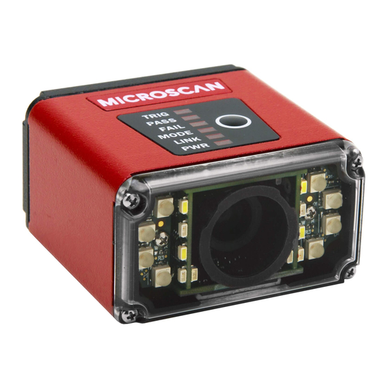
Page 50: Status Indicators
Chapter System Components Status Indicators MV-20 The top of the MicroHAWK MV-20 Smart Camera has an LED that indicates whether or not the device is powered-on. Power Indicator LED Power On PWR LED No Power Applied to Unit Additional User Feedback •... - Page 51 Green Flash – A green flash from the front of the unit indicates a Good Read. • Blue Targeting Pattern – The blue targeting pattern from the front of the unit allows the user to center an object in the camera’s field of view. MicroHAWK MV-20 / MV-30 / MV-40 Smart Camera Guide 2-35...
- Page 52 Chapter System Components 2-36 MicroHAWK MV-20 / MV-30 / MV-40 Smart Camera Guide...
-
Page 53: Getting Started With Autovision
Getting Started with CHAPTER 3 AutoVISION This section describes how to set up and use MicroHAWK MV-20, MV-30, and MV-40 Smart Cameras with AutoVISION Software. MicroHAWK MV-20 / MV-30 / MV-40 Smart Camera Guide... -
Page 54: Setting Up A Job In Autovision
Cordset, Host, Ethernet, M12 8-Pin Plug (Screw-On) to RJ45, 1 m. 99-000020-01 Photo Sensor, M12 4-Pin Plug, NPN, Dark Off, 2 m. Note: Additional cables available in the Microscan Product Pricing Catalog. 1. Configure MicroHAWK Hardware • Mount the camera as required by the application. - Page 55 MicroHAWK MV-40 with QX-1 Interface Device Common (12-Pin Plug to To Host 12-Pin (Ethernet Socket) 8-Pin Plug to RJ45) 5 or 6 Power Trigger Supply See Appendix A, Connector Pinouts, for MicroHAWK pin assignments. MicroHAWK MV-20 / MV-30 / MV-40 Smart Camera Guide...
- Page 56 AutoVISION's Connect view allows you to select your device and configure its settings, and to create a new job. The Select Device drop down menu provides a list of available devices. Hover the mouse over a device to see its details. MicroHAWK MV-20 / MV-30 / MV-40 Smart Camera Guide...
- Page 57 IP range as the default IP address. Default IP address: 192.168.188.2. Set the PC to the same IP range (example: 192.168.188.100). Important: When modifying camera settings, you will need to enter a username and password for the camera if a password has been defined. MicroHAWK MV-20 / MV-30 / MV-40 Smart Camera Guide...
- Page 58 Image view. This view allows you to Auto Calibrate the camera, and to manually adjust the camera's Exposure, Gain, and Focus, and also to set the Lighting Mode (On, Off, or Strobe). MicroHAWK MV-20 / MV-30 / MV-40 Smart Camera Guide...
- Page 59 Lighting. Inspection Outputs options allow you to connect your job to the outside world. This is also the view where you can add multiple tools to the job. The tool icons are located above the main view area. MicroHAWK MV-20 / MV-30 / MV-40 Smart Camera Guide...
- Page 60 Going to the Run view will automatically download your job to the camera and start it running. 5. Save the Job Click the Save to Camera icon on the File menu bar to save the job to the MicroHAWK. MicroHAWK MV-20 / MV-30 / MV-40 Smart Camera Guide...
-
Page 61: Profinet I/O And Ip Address Assignment
IP address. The device network viewer can be used to discover units with an APIPA address, connect to them, and update the IP address to a desired range. MicroHAWK MV-20 / MV-30 / MV-40 Smart Camera Guide... - Page 62 Chapter Getting Started with AutoVISION 3-10 MicroHAWK MV-20 / MV-30 / MV-40 Smart Camera Guide...
-
Page 63: Optics And Lighting
Optics and Lighting CHAPTER 4 This section describes the optical and illumination characteristics of MicroHAWK MV-20, MV-30, and MV-40 Smart Cameras. MicroHAWK MV-20 / MV-30 / MV-40 Smart Camera Guide... -
Page 64: Optics
Chapter Optics and Lighting Optics The monochrome and color versions of the MicroHAWK MV-20, MV-30, and MV-40 have a built-in CMOS sensor, available in Standard Density or High Density optics. MV-20 Fixed Focus MV-20 FOV Chart Fixed Focus Lens Type... - Page 65 UHD - FOV (mm) Distance (mm) (inch) Width Height Width Height Width Height 1.97 2.52 4.02 WVGA 7.48 11.81 15.75 1.97 2.52 4.02 SXGA 7.48 11.81 15.75 1.97 2.52 4.02 QSXGA 7.48 11.81 15.75 MicroHAWK MV-20 / MV-30 / MV-40 Smart Camera Guide...
- Page 66 752 x 480, 0.3 MP, Mono Global 10 fps / 60 fps SXGA 1280 x 960, 1.2 MP, Mono Global 10 fps / 42 fps QSXGA 2592 x 1944, 5 MP, Color Rolling 5 fps MicroHAWK MV-20 / MV-30 / MV-40 Smart Camera Guide...
-
Page 67: Illumination
Wavelength Expansion, Red 43-9500055-01 43-9500056-01 LA E65F-CAEB-24-1 617 nm Expansion, White 43-9500055-02 43-9500056-02 NFSW036BLT b3-b6/P9-P12 Expansion, IR 43-9500055-03 43-9500056-03 SFH 4259S 850 nm Expansion, Blue 43-9500055-04 43-9500056-04 LB E63C-T2V2-35-34 469 nm MicroHAWK MV-20 / MV-30 / MV-40 Smart Camera Guide... -
Page 68: Machine Vision Lighting Principles
(built-in red LEDs for monochrome sensors and white LEDs for color sensors). Depending on the requirements of your application, you may also need external lighting from Microscan’s NERLITE family of machine vision lighting products. Consider the following when setting up your application: •... -
Page 69: Microhawk Mv-40 External Illumination Control And Wiring
MicroHAWK MV-40 External Illumination Control and Wiring MicroHAWK MV-40 External Illumination Control and Wiring The MicroHAWK MV-40 Smart Camera supports external lighting with Microscan’s NERLITE Smart Series lights. The diagrams below demonstrates how the camera and light can be configured. The light is controlled using the Lighting control in the Camera configuration settings of AutoVISION software. - Page 70 Powering more than one MAX via the QX-1 will exceed your application. the QX-1’s current capacity. Operation Cable 1 Strobe 61-000218-01, Smart Series-to-QX-1, Strobe, NPN 2 ON/OFF 61-000207-01, Smart Series-to-QX-1, ON/OFF 3 Continuous ON 61-000204-01, Smart Series-to-QX-1, Continuous MicroHAWK MV-20 / MV-30 / MV-40 Smart Camera Guide...
- Page 71 MicroHAWK (Connector A) Signal Name Signal Name +24VDC Power Trigger – Output 3 DC Ground 7 and 12 Ground and Output Common Trigger + Power No Connection* * Insulate Pin 5 (gray wire) MicroHAWK MV-20 / MV-30 / MV-40 Smart Camera Guide...
- Page 72 Signal Name Signal Name +24VDC 2 and 12 Power and Output Common Trigger – Ground DC Ground Ground Trigger + Output 3 No Connection* * Insulate Pin 5 (gray wire) 4-10 MicroHAWK MV-20 / MV-30 / MV-40 Smart Camera Guide...
- Page 73 Power Trigger – 7 and 12 Ground and Output Common DC Ground 7 and 12 Ground and Output Common Trigger + Power Output 3 * Insulate Pin 5 (gray wire) MicroHAWK MV-20 / MV-30 / MV-40 Smart Camera Guide 4-11...
- Page 74 Connector Smart Series Illuminator MicroHAWK (Connector A) Signal Name Signal Name +24VDC Power Trigger – Ground DC Ground Ground Trigger + Power No Connection* * Insulate Pin 5 (gray wire) 4-12 MicroHAWK MV-20 / MV-30 / MV-40 Smart Camera Guide...
-
Page 75: Appendix A Connector Pinouts
Connector Pinouts APPENDIX A This section contains information about the MicroHAWK MV-20, MV-30, and MV-40 Smart Camera’s connectors and pin assignments. MicroHAWK MV-20 / MV-30 / MV-40 Smart Camera Guide... -
Page 76: Connector
Appendix Connector Pinouts MV-20 Connector Micro-USB Type B Socket Function Vbus (5V) D– Ground MicroHAWK MV-20 / MV-30 / MV-40 Smart Camera Guide... -
Page 77: Mv-30 Connector
MicroHAWK MV-30 Smart Camera Connector MV-30 Connector High-Density 15-Pin D-Sub Socket MicroHAWK MV-20 / MV-30 / MV-40 Smart Camera Guide... -
Page 78: Connector
Connector A – M12 12-Pin Plug – Power, I/O, and Serial Function Trigger Power Default Input 1, New Master Output 1 Output 3 Ground Input Common RS-232 (Host RxD) RS-232 (Host TxD) Output 2 Output Common MicroHAWK MV-20 / MV-30 / MV-40 Smart Camera Guide... - Page 79 MicroHAWK MV-40 Smart Camera Connector Connector B – M12 8-Pin Socket – Ethernet Function V– V– TX (–) RX (+) TX (+) RX (–) MicroHAWK MV-20 / MV-30 / MV-40 Smart Camera Guide...
- Page 80 Appendix Connector Pinouts MicroHAWK MV-20 / MV-30 / MV-40 Smart Camera Guide...
- Page 81 Cable Specifications APPENDIX B This section contains information about cables for the MicroHAWK MV-20, MV-30, and MV-40 Smart Cameras. Note: Cable specifications are published for information only. Microscan does not guarantee the performance or quality of cables provided by other suppliers.
-
Page 82: Appendix B Cable Specifications
3 feet long. This cable is used for basic communications-only applications. Micro-USB Shown with optional ferrite Type B core (98-9000035-01, Ferrite Type A Plug Core Snap-On Kit for USB Plug Cable – required for Class B Emissions) MicroHAWK MV-20 / MV-30 / MV-40 Smart Camera Guide... -
Page 83: Mv-30 Cables
The 61-9000037-01 DB15 to Ext. Power/RS-232 cable is cable with one end a 9-pin D-Sub socket connector (J1) and the other end a DB15 (J3) extended Power/RS-232 (J2). This cable is used for basic communications applications that require more light or use higher-speed applications. MicroHAWK MV-20 / MV-30 / MV-40 Smart Camera Guide... - Page 84 The 61-9000038-01 DB15 to ext. power/USB cable is a cable with one end a USB connector(J1) and the other end a DB15 (J3) extended power/RS-232 (J2). This cable is used for basic communications applications that require more light or for higher speed applications. MicroHAWK MV-20 / MV-30 / MV-40 Smart Camera Guide...
- Page 85 D-Sub socket connector (J1) and the other end a USB (J2) extended with a 2-pin socket (J3) and an 8-pin socket (J4) connector. This cable is used for virtual LAN or RS-232 with I/O applications, any speed with line stop or result indication. MicroHAWK MV-20 / MV-30 / MV-40 Smart Camera Guide...
- Page 86 15-pin D-Sub socket (J1) and the other end is a USB plug (J2). This cable is used for basic communications applications that require more light or for higher speed applications. MicroHAWK MV-20 / MV-30 / MV-40 Smart Camera Guide...
- Page 87 (J5) and a 15-pin D-Sub socket connector (J1), and the other end a USB (J2) extended with a 2-pin socket (J3) and an 8-pin socket (J4) connector. This cable is used for RS-232 applications with I/O for line stop or result indications. MicroHAWK MV-20 / MV-30 / MV-40 Smart Camera Guide...
-
Page 88: Mv-40 Cables
12-pin socket connector (J1) and the other end a 9-pin socket (J2) and an M12 plug (J3). This cable replaces common cord set, QX-1 and RS-232 cable with a single cable option. It is used for both RS-232 and WebLink simultaneously. MicroHAWK MV-20 / MV-30 / MV-40 Smart Camera Guide... - Page 89 12-pin socket connector (J1) and the other end a 98-9000022-01 USB keyboard wedge (9600 bps) (J2) and an M12 plug (J3). This cable is used with applications requiring keyboard input. MicroHAWK MV-20 / MV-30 / MV-40 Smart Camera Guide...
- Page 90 Appendix Cable Specifications Pinouts for Cordsets with Flying Leads Microscan offers two flying lead cordsets for use in hardware configurations: • 61-000166-02 (Plug, Screw-On) • 61-000167-02 (Socket, Screw-On) The diagrams below show the correspondence of wire colors to pins. 61-000166-02 – M12 12-Pin Plug to Flying Leads 61-000166-02 connects to Connector B (Serial) and QX-1 Connector 2.
-
Page 91: Appendix C General Specifications
General Specifications APPENDIX C This section contains specifications for the MicroHAWK MV-20, MV-30, and MV-40 Smart Cameras. MicroHAWK MV-20 / MV-30 / MV-40 Smart Camera Guide... -
Page 92: General Specifications
Standard Density (SD): 5.2 mm SD, HD: Factory set to 50, 102, 190, or 300 mm High Density (HD): 8.0 mm Ultra-High Density (UHD): 16.0 mm UHD: Factory set to 64 or 400 mm MicroHAWK MV-20 / MV-30 / MV-40 Smart Camera Guide... -
Page 93: Mv-30 General Specifications
64 or 400 mm (UHD) Autofocus: Software-adjustable 50 to 300 mm (SD, HD); Autofocus: Standard Density (5.2 mm); High Density (7.7 mm); Ultra-High Density (16.0 mm) 40 to 150 mm (UHD) MicroHAWK MV-20 / MV-30 / MV-40 Smart Camera Guide... -
Page 94: General Specifications
64 or 400 mm (UHD) Autofocus: Software-adjustable 50 to 300 mm (SD, HD); Autofocus: Standard Density (5.2 mm); High Density (7.7 mm); Ultra-High Density (16.0 mm) 40 to 150 mm (UHD) MicroHAWK MV-20 / MV-30 / MV-40 Smart Camera Guide... -
Page 95: Appendix D Serial Commands
Serial Commands APPENDIX D This section provides descriptions of the serial commands that can be sent to the camera via TCP (Telnet) port, AutoVISION Terminal, or HyperTerminal. MicroHAWK MV-20 / MV-30 / MV-40 Smart Camera Guide... - Page 96 Include an index to get a single value from an array such as GET int1. If the index is omitted, the full array of values will be returned in a comma-separated list of values. MicroHAWK MV-20 / MV-30 / MV-40 Smart Camera Guide...
- Page 97 GETIMAGE –transfer=ymodem –format=png –inspection=2 The following example will retrieve an image from the camera with these settings: Protocol: ymodem; Format: jpg (default); Quality: 50; Inspection: first inspection (default). GETIMAGE –transfer=ymodem –quality=50 MicroHAWK MV-20 / MV-30 / MV-40 Smart Camera Guide...
- Page 98 (available contiguous RAM – minimum target contiguous RAM) / 2. • User FTPs the job to /streamd0 • JOBLOAD: -mem -r Loads .avz from /streamd0 into RAM, deletes the RAMDisk /streamd0, and optionally starts the job (if -r is specified). MicroHAWK MV-20 / MV-30 / MV-40 Smart Camera Guide...
- Page 99 MEMINFO [-cp] [-v] Returns memory summary “avail/contig/frags” for device or coprocessor. Verbose. NETDRIVE [-type=]{RSH|FTP} [-host=n.n.n.n] [-user=user] [-password =password] Creates a network drive on the device. OFFLINE Stops all inspections. ONLINE Starts all inspections. MicroHAWK MV-20 / MV-30 / MV-40 Smart Camera Guide...
- Page 100 ‘/’ in the symbolic name path. SET avp/insp1/snapshot1/acq1/gain 2.0 paths are not case-sensitive and do not need to be fully qualified if unique. SET avp/acq1/gain 2.0 will set the same gain value if there is only one acquire. MicroHAWK MV-20 / MV-30 / MV-40 Smart Camera Guide...
- Page 101 !ERROR No such trigger when the index specified ‘n’ is out of range of virtual triggers. WHITEBAL Performs automatic calibration of white balance settings: RED gain, BLUE gain, and GREEN gain. MicroHAWK MV-20 / MV-30 / MV-40 Smart Camera Guide...
- Page 102 Appendix Serial Commands MicroHAWK MV-20 / MV-30 / MV-40 Smart Camera Guide...
-
Page 103: Usb Power Management (Mv-20 And Mv-30)
When your PC enters “sleep mode”, the USB ports may shut down and the camera may be disconnected. This section describes how to keep your PC’s USB ports active if the PC enters sleep mode or other low-power modes. MicroHAWK MV-20 / MV-30 / MV-40 Smart Camera Guide... - Page 104 MicroHAWK MV-20, MV-30, or MV-40. From the Windows Start menu, right-click on Computer and select Properties. Select Device Manager from the options at the left side of the screen. MicroHAWK MV-20 / MV-30 / MV-40 Smart Camera Guide...
- Page 105 Allow the computer to turn off this device to save power. Repeat steps 3 and 4 for each USB Root Hub item in the Universal Serial Bus controllers list. MicroHAWK MV-20 / MV-30 / MV-40 Smart Camera Guide...
- Page 106 Appendix USB Power Management (MV-20 and MV-30) MicroHAWK MV-20 / MV-30 / MV-40 Smart Camera Guide...
-
Page 107: Tcp/Udp And General Port Usage
TCP/UDP and General Port APPENDIX F Usage This section lists the ports used by MicroHAWK Smart Cameras for communication. MicroHAWK MV-20 / MV-30 / MV-40 Smart Camera Guide... -
Page 108: Microhawk Ports
49049 49050 PIC/LIVE 49200 REPORT 49202 REPORTCONTROL 49201 PARTQ 49079 KEEPALIVE 49211 Serial TCP#1 49212 Serial TCP#2 49213 Serial TCP#3 49214 Serial TCP#4 49497 UDP BROADCAST 49496 UDP COMMAND TELNET HTTP MicroHAWK MV-20 / MV-30 / MV-40 Smart Camera Guide...
Need help?
Do you have a question about the MicroHAWK MV-20 and is the answer not in the manual?
Questions and answers